indicator ISUZU KB P190 2007 Workshop Manual PDF
[x] Cancel search | Manufacturer: ISUZU, Model Year: 2007, Model line: KB P190, Model: ISUZU KB P190 2007Pages: 6020, PDF Size: 70.23 MB
Page 1256 of 6020
6E-222 Engine Control System (4JH1)
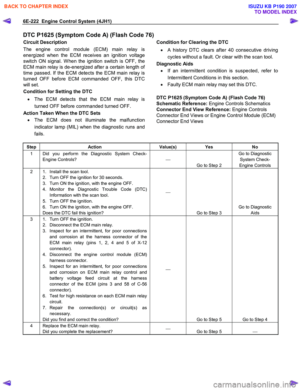
DTC P1625 (Symptom Code A) (Flash Code 76)
Circuit Description
The engine control module (ECM) main relay is
energized when the ECM receives an ignition voltage
switch ON signal. W hen the ignition switch is OFF, the
ECM main relay is de-energized after a certain length o
f
time passed. If the ECM detects the ECM main relay is
turned OFF before ECM commanded OFF, this DTC
will set.
Condition for Setting the DTC
• The ECM detects that the ECM main relay is
turned OFF before commanded turned OFF.
Action Taken When the DTC Sets • The ECM does not illuminate the malfunction
indicator lamp (MIL) when the diagnostic runs and
fails.
Condition for Clearing the DTC
• A history DTC clears after 40 consecutive driving
cycles without a fault. Or clear with the scan tool.
Diagnostic Aids
• If an intermittent condition is suspected, refer to
Intermittent Conditions in this section.
• Faulty ECM main relay may set this DTC.
DTC P1625 (Symptom Code A) (Flash Code 76)
Schematic Reference: Engine Controls Schematics
Connector End View Reference: Engine Controls
Connector End Views or Engine Control Module (ECM)
Connector End Views
Step Action Value(s) Yes No
1 Did you perform the Diagnostic System Check-
Engine Controls?
Go to Step 2 Go to Diagnostic
System Check-
Engine Controls
2 1. Install the scan tool. 2. Turn OFF the ignition for 30 seconds.
3. Turn ON the ignition, with the engine OFF.
4. Monitor the Diagnostic Trouble Code (DTC) Information with the scan tool.
5. Turn OFF the ignition.
6. Turn ON the ignition, with the engine OFF.
Does the DTC fail this ignition?
Go to Step 3 Go to Diagnostic
Aids
3 1. Turn OFF the ignition. 2. Disconnect the ECM main relay.
3. Inspect for an intermittent, for poor connections and corrosion at the harness connector of the
ECM main relay (pins 1, 2, 4 and 5 of X-12
connector).
4. Disconnect the engine control module (ECM) harness connector.
5. Inspect for an intermittent, for poor connections and corrosion on ECM main relay control and
battery voltage feed circuit at the harness
connector of the ECM (pins 3 and 58 of C-56
connector).
6. Test for high resistance on each ECM main relay circuit.
7. Repair the connection(s) or circuit(s) as necessary.
Did you find and correct the condition?
Go to Step 5 Go to Step 4
4 Replace the ECM main relay. Did you complete the replacement?
Go to Step 5
BACK TO CHAPTER INDEX
TO MODEL INDEX
ISUZU KB P190 2007
Page 1258 of 6020
6E-224 Engine Control System (4JH1)
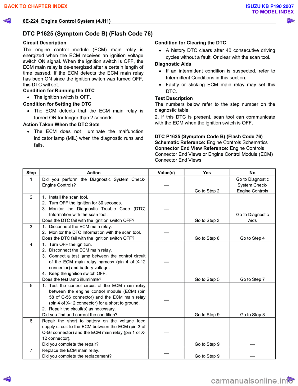
DTC P1625 (Symptom Code B) (Flash Code 76)
Circuit Description
The engine control module (ECM) main relay is
energized when the ECM receives an ignition voltage
switch ON signal. W hen the ignition switch is OFF, the
ECM main relay is de-energized after a certain length o
f
time passed. If the ECM detects the ECM main relay
has been ON since the ignition switch was turned OFF,
this DTC will set.
Condition for Running the DTC
• The ignition switch is OFF.
Condition for Setting the DTC • The ECM detects that the ECM main relay is
turned ON for longer than 2 seconds.
Action Taken When the DTC Sets • The ECM does not illuminate the malfunction
indicator lamp (MIL) when the diagnostic runs and
fails.
Condition for Clearing the DTC
• A history DTC clears after 40 consecutive driving
cycles without a fault. Or clear with the scan tool.
Diagnostic Aids
• If an intermittent condition is suspected, refer to
Intermittent Conditions in this section.
• Faulty or sticking ECM main relay may set this
DTC.
Test Description
The numbers below refer to the step number on the
diagnostic table.
2. If this DTC is present, scan tool can communicate
with the ECM when the ignition switch is OFF.
DTC P1625 (Symptom Code B) (Flash Code 76)
Schematic Reference: Engine Controls Schematics
Connector End View Reference: Engine Controls
Connector End Views or Engine Control Module (ECM)
Connector End Views
Step Action Value(s) Yes No
1 Did you perform the Diagnostic System Check-
Engine Controls?
Go to Step 2 Go to Diagnostic
System Check-
Engine Controls
2 1. Install the scan tool. 2. Turn OFF the ignition for 30 seconds.
3. Monitor the Diagnostic Trouble Code (DTC) Information with the scan tool.
Does the DTC fail with the ignition switch OFF?
Go to Step 3 Go to Diagnostic
Aids
3 1. Disconnect the ECM main relay. 2. Monitor the DTC Information with the scan tool.
Does the DTC fail with the ignition switch OFF?
Go to Step 6 Go to Step 4
4 1. Turn OFF the ignition. 2. Disconnect the ECM main relay.
3. Connect a test lamp between the control circuit of the ECM main relay harness (pin 4 of X-12
connector) and battery voltage.
4. Keep the ignition switch OFF.
Does the test lamp illuminate?
Go to Step 5 Go to Step 7
5 1. Test the control circuit of the ECM main relay between the engine control module (ECM) (pin
58 of C-56 connector) and the ECM main relay
(pin 4 of X-12 connector) for a short to ground.
2. Repair the circuit(s) as necessary.
Did you find and correct the condition?
Go to Step 9 Go to Step 8
6 Repair the short to battery on the voltage feed supply circuit to the ECM between the ECM (pin 3 of
C-56 connector) and the ECM main relay (pin 1 of X-
12 connector).
Did you complete the repair?
Go to Step 9
7 Replace the ECM main relay.
Did you complete the replacement?
Go to Step 9
BACK TO CHAPTER INDEX
TO MODEL INDEX
ISUZU KB P190 2007
Page 1268 of 6020
6E-234 Engine Control System (4JH1)
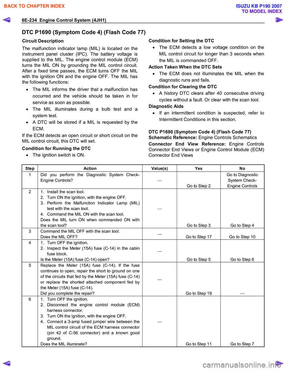
DTC P1690 (Symptom Code 4) (Flash Code 77)
Circuit Description
The malfunction indicator lamp (MIL) is located on the
instrument panel cluster (IPC). The battery voltage is
supplied to the MIL. The engine control module (ECM)
turns the MIL ON by grounding the MIL control circuit.
After a fixed time passes, the ECM turns OFF the MIL
with the ignition ON and the engine OFF. The MIL has
the following functions:
• The MIL informs the driver that a malfunction has
occurred and the vehicle should be taken in fo
r
service as soon as possible.
• The MIL illuminates during a bulb test and a
system test.
•
A DTC will be stored if a MIL is requested by the
ECM.
If the ECM detects an open circuit or short circuit on the
MIL control circuit, this DTC will set.
Condition for Running the DTC • The ignition switch is ON.
Condition for Setting the DTC
• The ECM detects a low voltage condition on the
MIL control circuit for longer than 3 seconds when
the MIL is commanded OFF.
Action Taken When the DTC Sets • The ECM does not illuminates the MIL when the
diagnostic runs and fails.
Condition for Clearing the DTC • A history DTC clears after 40 consecutive driving
cycles without a fault. Or clear with the scan tool.
Diagnostic Aids
• If an intermittent condition is suspected, refer to
Intermittent Conditions in this section.
DTC P1690 (Symptom Code 4) (Flash Code 77)
Schematic Reference: Engine Controls Schematics
Connector End View Reference: Engine Controls
Connector End Views or Engine Control Module (ECM)
Connector End Views
Step Action Value(s) Yes No
1 Did you perform the Diagnostic System Check-
Engine Controls?
Go to Step 2 Go to Diagnostic
System Check-
Engine Controls
2 1. Install the scan tool. 2. Turn ON the ignition, with the engine OFF.
3. Perform the Malfunction Indicator Lamp (MIL) test with the scan tool.
4. Command the MIL ON with the scan tool.
Does the MIL turn ON when commanded ON with
the scan tool?
Go to Step 3 Go to Step 4
3 Command the MIL OFF with the scan tool. Does the MIL OFF?
Go to Step 17 Go to Step 10
4 1. Turn OFF the ignition.
2. Inspect the Meter (15A) fuse (C-14) in the cabin fuse block.
Is the Meter (15A) fuse (C-14) open?
Go to Step 5 Go to Step 6
5 Replace the Meter (15A) fuse (C-14). If the fuse continues to open, repair the short to ground on one
of the circuits that fed by the Meter (15A) fuse (C-14)
or replace the shorted attached component fed by
the Meter (15A) fuse (C-14).
Did you complete the repair?
Go to Step 19
6 1. Turn OFF the ignition.
2. Disconnect the engine control module (ECM) harness connector.
3. Turn ON the ignition, with the engine OFF.
4. Connect a 3-amp fused jumper wire between the MIL control circuit of the ECM harness connector
(pin 42 of C-56 connector) and a known good
ground.
Does the MIL illuminate?
Go to Step 11 Go to Step 7
BACK TO CHAPTER INDEX
TO MODEL INDEX
ISUZU KB P190 2007
Page 1271 of 6020
Engine Control System (4JH1) 6E-237
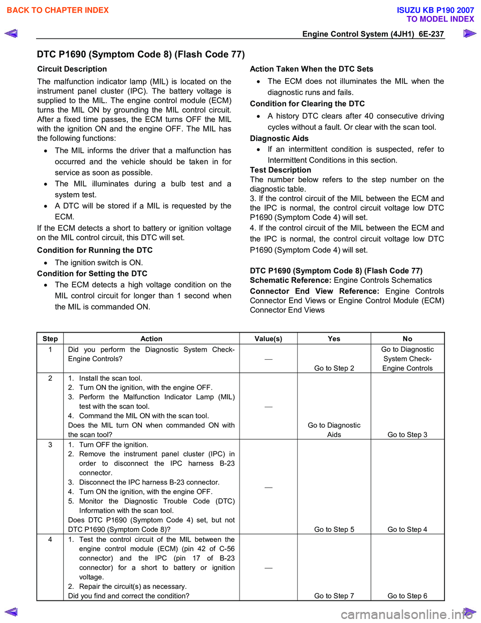
DTC P1690 (Symptom Code 8) (Flash Code 77)
Circuit Description
The malfunction indicator lamp (MIL) is located on the
instrument panel cluster (IPC). The battery voltage is
supplied to the MIL. The engine control module (ECM)
turns the MIL ON by grounding the MIL control circuit.
After a fixed time passes, the ECM turns OFF the MIL
with the ignition ON and the engine OFF. The MIL has
the following functions:
• The MIL informs the driver that a malfunction has
occurred and the vehicle should be taken in fo
r
service as soon as possible.
• The MIL illuminates during a bulb test and a
system test.
•
A DTC will be stored if a MIL is requested by the
ECM.
If the ECM detects a short to battery or ignition voltage
on the MIL control circuit, this DTC will set.
Condition for Running the DTC • The ignition switch is ON.
Condition for Setting the DTC
• The ECM detects a high voltage condition on the
MIL control circuit for longer than 1 second when
the MIL is commanded ON.
Action Taken When the DTC Sets
• The ECM does not illuminates the MIL when the
diagnostic runs and fails.
Condition for Clearing the DTC
• A history DTC clears after 40 consecutive driving
cycles without a fault. Or clear with the scan tool.
Diagnostic Aids
• If an intermittent condition is suspected, refer to
Intermittent Conditions in this section.
Test Description
The number below refers to the step number on the
diagnostic table.
3. If the control circuit of the MIL between the ECM and
the IPC is normal, the control circuit voltage low DTC
P1690 (Symptom Code 4) will set.
4. If the control circuit of the MIL between the ECM and
the IPC is normal, the control circuit voltage low DTC
P1690 (Symptom Code 4) will set.
DTC P1690 (Symptom Code 8) (Flash Code 77)
Schematic Reference: Engine Controls Schematics
Connector End View Reference: Engine Controls
Connector End Views or Engine Control Module (ECM)
Connector End Views
Step Action Value(s) Yes No
1 Did you perform the Diagnostic System Check-
Engine Controls?
Go to Step 2 Go to Diagnostic
System Check-
Engine Controls
2 1. Install the scan tool. 2. Turn ON the ignition, with the engine OFF.
3. Perform the Malfunction Indicator Lamp (MIL) test with the scan tool.
4. Command the MIL ON with the scan tool.
Does the MIL turn ON when commanded ON with
the scan tool?
Go to Diagnostic Aids Go to Step 3
3 1. Turn OFF the ignition. 2. Remove the instrument panel cluster (IPC) in order to disconnect the IPC harness B-23
connector.
3. Disconnect the IPC harness B-23 connector.
4. Turn ON the ignition, with the engine OFF.
5. Monitor the Diagnostic Trouble Code (DTC) Information with the scan tool.
Does DTC P1690 (Symptom Code 4) set, but not
DTC P1690 (Symptom Code 8)?
Go to Step 5 Go to Step 4
4 1. Test the control circuit of the MIL between the engine control module (ECM) (pin 42 of C-56
connector) and the IPC (pin 17 of B-23
connector) for a short to battery or ignition
voltage.
2. Repair the circuit(s) as necessary.
Did you find and correct the condition?
Go to Step 7 Go to Step 6
BACK TO CHAPTER INDEX
TO MODEL INDEX
ISUZU KB P190 2007
Page 1289 of 6020
Engine Control System (4JH1) 6E-255
Symptoms – Engine Controls
Symptoms – Engine Controls
Important Preliminary Inspections Before Starting
Perform Diagnostic System Check – Engine Controls
before using the symptom tables, and verify that all o
f
the following are true:
• The engine control module (ECM) and malfunction
indicator lamp (MIL) are operating correctly.
• There are no diagnostic trouble codes (DTCs)
stored, or a DTC exists but without the MIL.
• The scan tool data is within the normal operating
range. Refer to scan tool Data List in this section.
• Verify the customer concern and locate the correct
symptom in the table of contents. Inspect the items
indicated under that symptom.
Visual and Physical Inspection
Several of the symptom procedures ask for careful
visual and physical inspection. This step is extremel
y
important. The visual and physical inspection can lead
to correcting a problem without further inspections, and
can save valuable time. Ensure that:
• The ECM grounds are clean, tight, and in thei
r
proper location.
• The vacuum hoses are not split or kinked, and
properly connected. Inspect thoroughly for an
y
type of leak or restriction.
• The mass air flow (MAF) sensor is properl
y
installed. The arrows on the plastic portion of the
sensor must point toward the engine.
• The air intake ducts are not collapsed or damaged.
• There are no leaks at the MAF sensor, an
y
connections or intake manifold sealing surfaces.
• The engine harness wiring and terminals are
properly connected and are not pinched or cut.
Intermittent
Important:
Inspect for improper installation of electrical
components if an intermittent condition exists. Inspect
for aftermarket add-on electrical equipment devices,
lights, and cellular phones. Verify that no aftermarket
equipment is connected to the keyword 2000 serial data
circuit. If you cannot locate an intermittent condition, a
cellular phone communication signal may cause the
condition.
Important:
The problem may or may not turn ON the MIL or store a
DTC.
Faulty electrical connections or wiring cause most
intermittent problems. Perform a careful visual and
physical inspection of the suspect connectors for the
following conditions:
• Improperly mated connector halves
• Terminals that are not seated
• Terminals that are damaged or improperly formed
Reform or replace connector terminals in the problem
circuit in order to ensure proper contact tension.
Remove the terminal from the connector body in orde
r
to inspect for poor terminal wire connection.
Road test the vehicle with the DMM connected to the
suspected circuit. An abnormal reading that occurs
when the malfunction occurs is a good indication that
there is a malfunction in the circuit being monitored.
Use the scan tool in order to help detect intermittent
conditions. Useful features of the scan tool include the
following:
• Trigger the Snapshot feature in order to capture
and store engine parameters when the malfunction
occurs. Review this stored information in order to
see the specific running conditions that caused the
malfunction.
• Use the Plot Function on the scan tool in order to
plot selected data parameters. Review this stored
information to aid in locating an intermittent
problem. Refer to the scan tool Users Guide fo
r
more information.
Important:
If the intermittent condition exists as a start and then
stall, test for DTCs relating to the vehicle theft deterrent
system. Test for improper installation of electrical
options such as lights, cellular phones, etc.
Any of the following may cause an intermittent MIL with
no stored DTC:
• The ECM grounds are loose or dirty. Refer to
Engine Controls Schematics.
• The MIL circuit intermittently shorted to ground.
• Electrical system interference caused by a
malfunctioning relay, ECM driven solenoid, o
r
switch. The electrical component can cause a
sharp electrical surge. Normally, the problem will
occur when the malfunctioning component is
operating.
• There is an open diode across the A/C
compressor clutch or any other open diodes.
BACK TO CHAPTER INDEX
TO MODEL INDEX
ISUZU KB P190 2007
Page 1317 of 6020
Engine Control System (4JH1) 6E-283
Description And Operation
Engine Control Module (ECM) Description
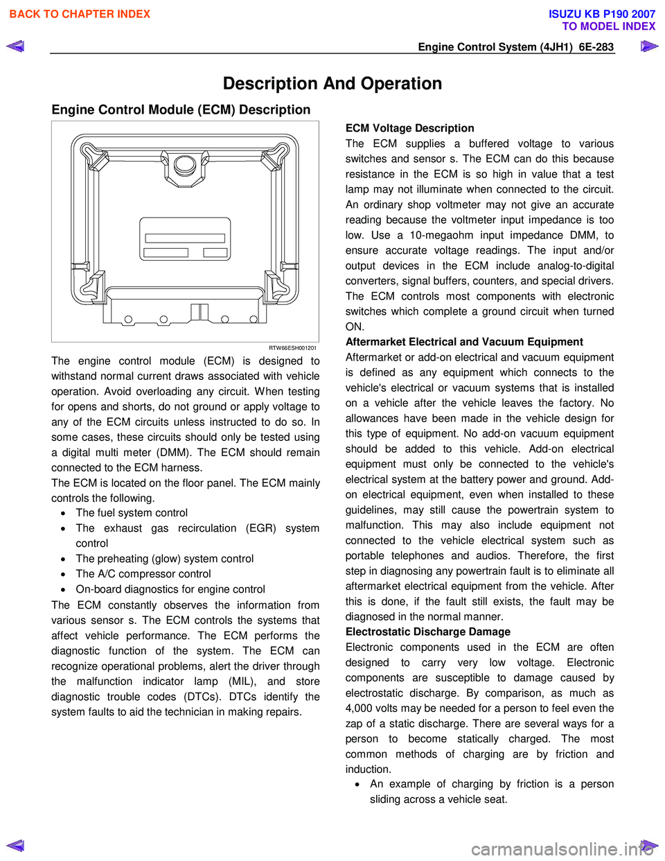
RTW 66ESH001201
The engine control module (ECM) is designed to
withstand normal current draws associated with vehicle
operation. Avoid overloading any circuit. W hen testing
for opens and shorts, do not ground or apply voltage to
any of the ECM circuits unless instructed to do so. In
some cases, these circuits should only be tested using
a digital multi meter (DMM). The ECM should remain
connected to the ECM harness.
The ECM is located on the floor panel. The ECM mainl
y
controls the following.
• The fuel system control
• The exhaust gas recirculation (EGR) system
control
• The preheating (glow) system control
• The A/C compressor control
• On-board diagnostics for engine control
The ECM constantly observes the information from
various sensor s. The ECM controls the systems that
affect vehicle performance. The ECM performs the
diagnostic function of the system. The ECM can
recognize operational problems, alert the driver through
the malfunction indicator lamp (MIL), and store
diagnostic trouble codes (DTCs). DTCs identify the
system faults to aid the technician in making repairs.
ECM Voltage Description
The ECM supplies a buffered voltage to various
switches and sensor s. The ECM can do this because
resistance in the ECM is so high in value that a test
lamp may not illuminate when connected to the circuit.
An ordinary shop voltmeter may not give an accurate
reading because the voltmeter input impedance is too
low. Use a 10-megaohm input impedance DMM, to
ensure accurate voltage readings. The input and/o
r
output devices in the ECM include analog-to-digital
converters, signal buffers, counters, and special drivers.
The ECM controls most components with electronic
switches which complete a ground circuit when turned
ON.
Aftermarket Electrical and Vacuum Equipment
Aftermarket or add-on electrical and vacuum equipment
is defined as any equipment which connects to the
vehicle's electrical or vacuum systems that is installed
on a vehicle after the vehicle leaves the factory. No
allowances have been made in the vehicle design fo
r
this type of equipment. No add-on vacuum equipment
should be added to this vehicle. Add-on electrical
equipment must only be connected to the vehicle's
electrical system at the battery power and ground. Add-
on electrical equipment, even when installed to these
guidelines, may still cause the powertrain system to
malfunction. This may also include equipment not
connected to the vehicle electrical system such as
portable telephones and audios. Therefore, the first
step in diagnosing any powertrain fault is to eliminate all
aftermarket electrical equipment from the vehicle. Afte
r
this is done, if the fault still exists, the fault may be
diagnosed in the normal manner.
Electrostatic Discharge Damage
Electronic components used in the ECM are often
designed to carry very low voltage. Electronic
components are susceptible to damage caused b
y
electrostatic discharge. By comparison, as much as
4,000 volts may be needed for a person to feel even the
zap of a static discharge. There are several ways for a
person to become statically charged. The most
common methods of charging are by friction and
induction. •
An example of charging by friction is a person
sliding across a vehicle seat.
BACK TO CHAPTER INDEX
TO MODEL INDEX
ISUZU KB P190 2007
Page 1318 of 6020
6E-284 Engine Control System (4JH1)
Important:
To prevent possible electrostatic discharge damage,
follow these guidelines: • Do not touch the ECM connector pins or soldered
components on the ECM circuit board.
• Do not open the replacement part package until
the part is ready to be installed.
• Before removing the part from the package,
ground the package to a known good ground on
the vehicle.
• If the part has been handled while sliding across
the seat, while sitting down from a standing
position, or while walking a distance, touch a
known good ground before installing the part.
• Charge by induction occurs when a person with
well insulated shoes stands near a highly charged
object and momentarily touches ground. Charges
of the same polarity are drained off leaving the
person highly charged with opposite polarity.
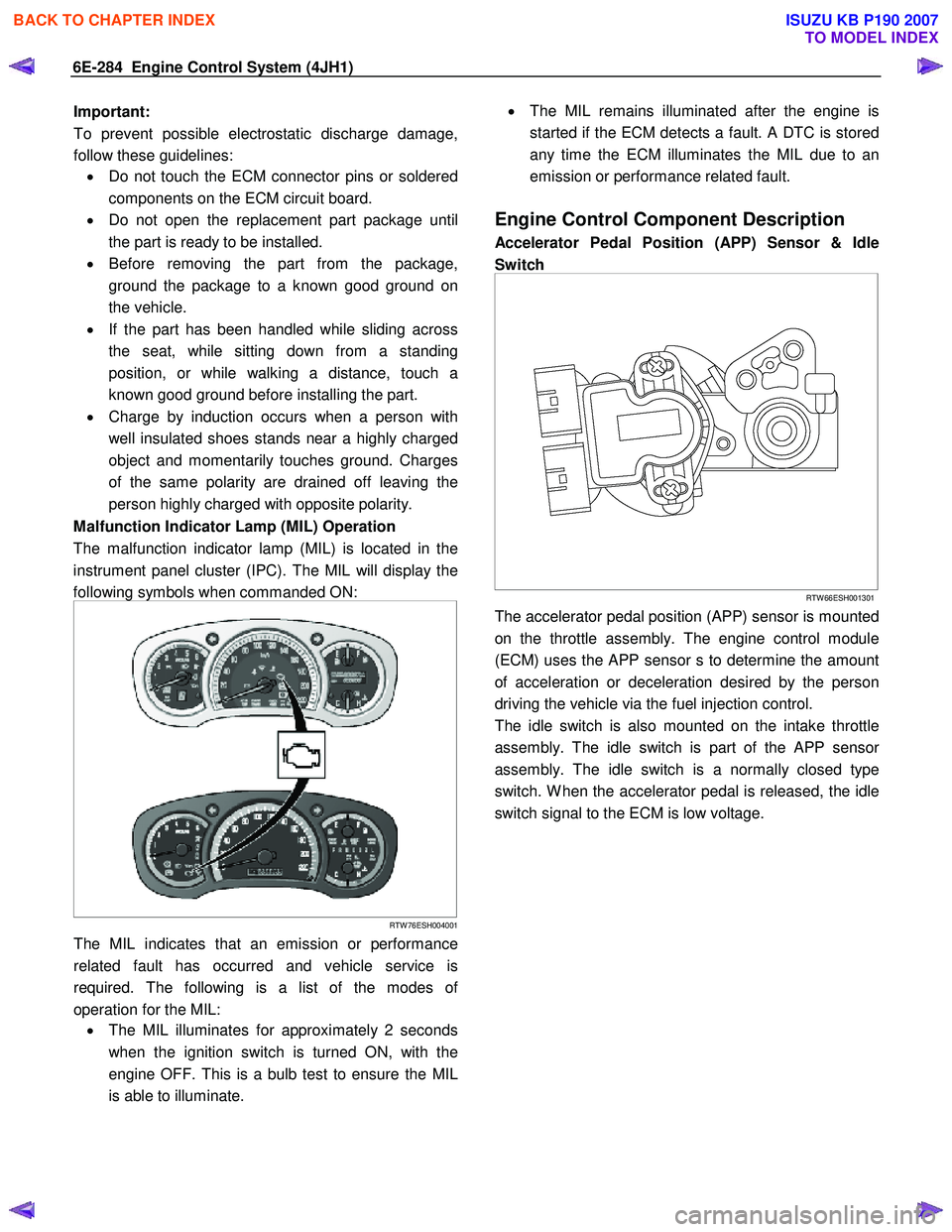
Malfunction Indicator Lamp (MIL) Operation
The malfunction indicator lamp (MIL) is located in the
instrument panel cluster (IPC). The MIL will display the
following symbols when commanded ON:
RTW 76ESH004001
The MIL indicates that an emission or performance
related fault has occurred and vehicle service is
required. The following is a list of the modes o
f
operation for the MIL: • The MIL illuminates for approximately 2 seconds
when the ignition switch is turned ON, with the
engine OFF. This is a bulb test to ensure the MIL
is able to illuminate.
•
The MIL remains illuminated after the engine is
started if the ECM detects a fault. A DTC is stored
any time the ECM illuminates the MIL due to an
emission or performance related fault.
Engine Control Component Description
Accelerator Pedal Position (APP) Sensor & Idle
Switch
RTW 66ESH001301
The accelerator pedal position (APP) sensor is mounted
on the throttle assembly. The engine control module
(ECM) uses the APP sensor s to determine the amount
of acceleration or deceleration desired by the person
driving the vehicle via the fuel injection control.
The idle switch is also mounted on the intake throttle
assembly. The idle switch is part of the APP senso
r
assembly. The idle switch is a normally closed type
switch. W hen the accelerator pedal is released, the idle
switch signal to the ECM is low voltage.
BACK TO CHAPTER INDEX
TO MODEL INDEX
ISUZU KB P190 2007
Page 1351 of 6020
6F – 18 EXHAUST SYSTEM
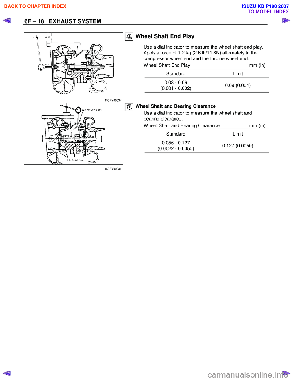
Wheel Shaft End Play
Use a dial indicator to measure the wheel shaft end play.
Apply a force of 1.2 kg (2.6 lb/11.8N) alternately to the
compressor wheel end and the turbine wheel end.
W heel Shaft End Play mm (in)
Standard Limit
0.03 - 0.06
(0.001 - 0.002) 0.09 (0.004)
150RY00034
Wheel Shaft and Bearing Clearance
Use a dial indicator to measure the wheel shaft and
bearing clearance.
W heel Shaft and Bearing Clearance mm (in)
Standard Limit
0.056 - 0.127
(0.0022 - 0.0050) 0.127 (0.0050)
150RY00036
BACK TO CHAPTER INDEX
TO MODEL INDEX
ISUZU KB P190 2007
Page 1365 of 6020

ENGINE MECHANICAL (4JK1/4JJ1) 6A-5
EGR system
Based upon data, including water temperature, engine
speeds or engine loads, it is controlled via Engine
Control Module (ECM) to purify exhaust by recycling
part of it.
Its main components include an EGR valve, an EGR
cooler and various sensors.
Connecting rod cap bolt
The angular tightening method of the connecting rod
cap bolt further increases reliability and durability.
Fuel rail-type electronic control injection system
The fuel rail-type electronic control injection system is
composed of a fuel supply pump that sets the target
pressure of high-pressure fuel and supply it, a fuel rail
that measures such high-pressure fuel and a fuel
injector that turns it into a fine spray and injects it. Each
is controlled via ECM based upon various signals, while
injection timing or fuel injection quantity is controlled
under every possible driving condition.
Fuel injector
The fuel injector is a 6-hole nozzle that adjusts fuel
injection quantity or injection timing by opening o
r
closing an electromagnetic valve on the head of the fuel
injector.
ECM corrects the dispersion of fuel injection quantit
y
between fuel injector according to ID code data in
memory. At the replacement of fuel injector, ID code
data should be stored in ECM.
Fuel filter with sedimenter
It is a fuel filter with sedimenter that gets rid of water by
making use of the difference in specific gravity between
light oil and water, which comes with an indicator that
notifies you that it is filled with water.
Preheating system
The preheating system consists of the ECM, the glow
relay, glow plugs and the glow indicator lamp. The
preheating system is operated when the engine coolant
temperature is low, and makes the engine easy to start.
Lubrication system
It is an oil filter with full-flow bypass, which uses a
water-cool oil cooler and oil jet to cool the piston.
Functional inspection
Inspection/adjustment of valve clearance 1. Inspection of valve clearance
• Remove the fuel injector harness assembly.
• Remove the leak off hose.
• Remove the cylinder head cover.
• Rotate the crankshaft to make the No.1
cylinder meet the compression top dead cente
r
(TDC).
RTW 76ASH001301
Legend
1. TDC
BACK TO CHAPTER INDEX
TO MODEL INDEX
ISUZU KB P190 2007
Page 1423 of 6020

ENGINE MECHANICAL (4JK1/4JJ1) 6A-63
LNW 21BSH020501
8. Check if the camshaft is runout.
• Place the camshaft on a V block to measure a
runout with a dial gauge.
• Rotate the camshaft slowly to measure ho
w
much the dial indicator shook. If it exceeds the
limit, replace the camshaft.
Runout of the camshaft mm (in)
Limit 0.05 (0.0020)
LNW 21BSH020601
9. Measure a camshaft journal oil clearance.
a. Measure an inside diameter of the camshaft bearing with a dial gauge.
b. Read the difference between the inside diameter of the camshaft bearing and the
diameter of the camshaft journal.
If the measured oil clearance exceeds the limit, replace the camshaft bearing.
Clearance of the journal part mm (in)
Standard 0.025
− 0.087
(0.0010 − 0.0034)
Limit 0.15 (0.0059)
LNW 21BSH054601
Reassembly
1. Install the dowel pin.
2. Install the camshaft gear. • Align the knock pin with the slot in the camshaft
gear. Use a press to install the camshaft gea
r
to the camshaft.
RTW 56ASH006601
Legend
1. Camshaft
2. Dowel Pin
3. Camshaft Gear
BACK TO CHAPTER INDEX
TO MODEL INDEX
ISUZU KB P190 2007