sensor ISUZU KB P190 2007 Workshop Repair Manual
[x] Cancel search | Manufacturer: ISUZU, Model Year: 2007, Model line: KB P190, Model: ISUZU KB P190 2007Pages: 6020, PDF Size: 70.23 MB
Page 4428 of 6020

7A2-144 TRANSMISSION CONTROL SYSTEM (JR405E)
The JR405E automatic transmission is electrically
controlled by a transmission control module (TCM).
There are four forward speeds and one reverse speed.
This JR405E automatic transmission employs a clutch
pressure direct control system (Direct Electronic Shift
Control: DESC) using duty cycle type solenoid valves,
which ensure high shift quality. This transmission also
has a learning function and constantly checks the time
of each clutch and brake required for the shift in order
to match this time with the target value for the optimum
shift. The TCM will automatically select the most
appropriate shift points and lock-up points depending
on the accelerator pedal opening, the vehicle speed
and the vehicle load. If any trouble arises in the speed
sensor, solenoid valve, etc., the fail-safe control
function is activated to keep the running performance.
The JR405E automatic transmission consists of the
torque converter, oil pump, input shaft, out put shaft,
planetary gears and valve body. The gear train consists
of two planetary gear sets and three multiple plate
clutches in combination with two multiple plate brakes
and a one-way clutch.
Transmission Component Description
Torque Converter
Legend
1. Pump impeller
2. Turbine runner
3. Stator
4. Converter front cover
5. One-way clutch
6. Torque converter clutch (TCC) piston
7. Torsion damper
The torque converter is a device for transmitting the
engine torque to the transmission. It transmits power by
means of oil when the lock up clutch is disengaged,
and by means of a lock up clutch when it is engaged. The torque converter is of the symmetrical, three-
element, single-stage, two-phase type. As shown in the
picture, the symmetrical three-elements refer to three
elements (components) consisting of impeller (1),
turbine (2) and stator (3) that are arranged
symmetrically. Single-stage means that there is only
one turbine as an output element; two-phase means
that the pump impeller acts as a torque converter when
the turbine speed is comparatively low, and as a fluid
coupling when the speed is high. Lock up refers to a
fixed state of the lock up clutch (=torque converter
clutch (TCC) inside the torque converter and thus
connects the engine directly to the transmission.
Oil Pump
Legend 1. Torque converter
2. Oil pump
BACK TO CHAPTER INDEX
TO MODEL INDEX
ISUZU KB P190 2007
Page 4432 of 6020
7A2-148 TRANSMISSION CONTROL SYSTEM (JR405E)
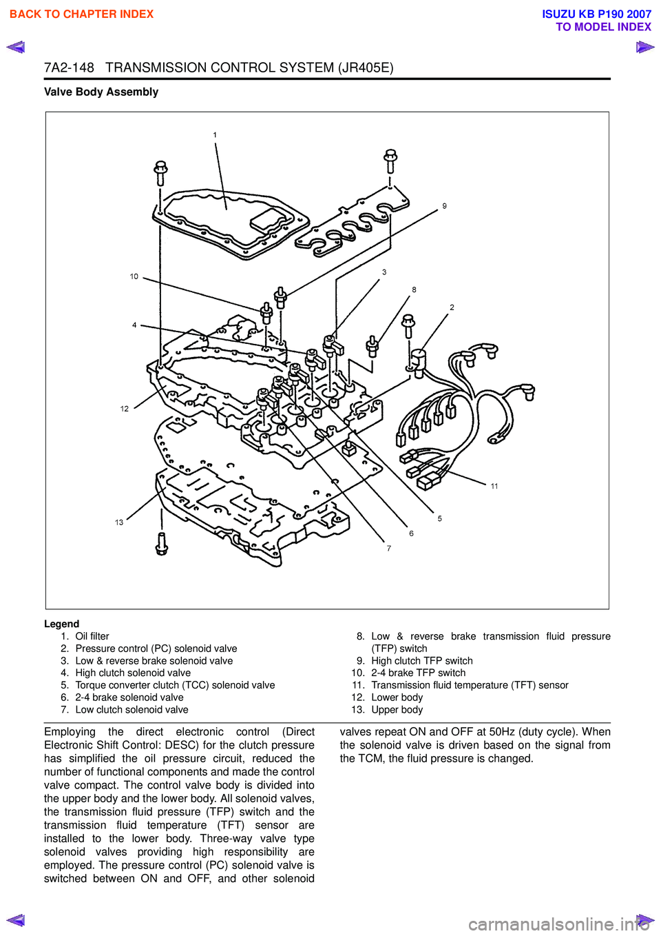
Valve Body Assembly
Legend1. Oil filter
2. Pressure control (PC) solenoid valve
3. Low & reverse brake solenoid valve
4. High clutch solenoid valve
5. Torque converter clutch (TCC) solenoid valve
6. 2-4 brake solenoid valve
7. Low clutch solenoid valve 8. Low & reverse brake transmission fluid pressure
(TFP) switch
9. High clutch TFP switch
10. 2-4 brake TFP switch
11. Transmission fluid temperature (TFT) sensor
12. Lower body
13. Upper body
Employing the direct electronic control (Direct
Electronic Shift Control: DESC) for the clutch pressure
has simplified the oil pressure circuit, reduced the
number of functional components and made the control
valve compact. The control valve body is divided into
the upper body and the lower body. All solenoid valves,
the transmission fluid pressure (TFP) switch and the
transmission fluid temperature (TFT) sensor are
installed to the lower body. Three-way valve type
solenoid valves providing high responsibility are
employed. The pressure control (PC) solenoid valve is
switched between ON and OFF, and other solenoid valves repeat ON and OFF at 50Hz (duty cycle). When
the solenoid valve is driven based on the signal from
the TCM, the fluid pressure is changed.
BACK TO CHAPTER INDEX
TO MODEL INDEX
ISUZU KB P190 2007
Page 4433 of 6020
TRANSMISSION CONTROL SYSTEM (JR405E) 7A2-149
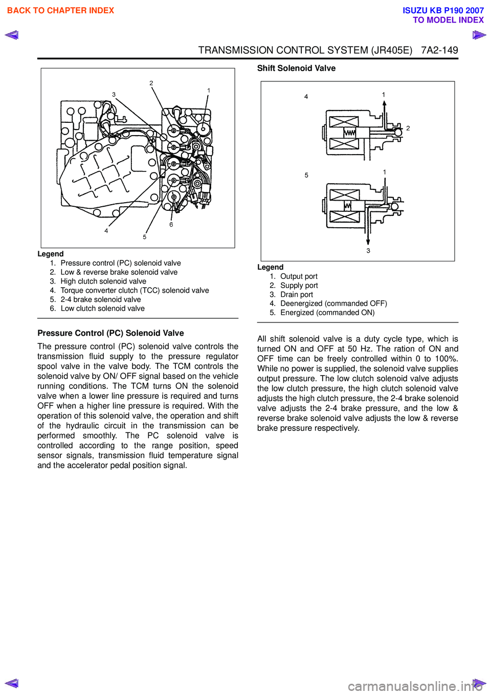
Legend1. Pressure control (PC) solenoid valve
2. Low & reverse brake solenoid valve
3. High clutch solenoid valve
4. Torque converter clutch (TCC) solenoid valve
5. 2-4 brake solenoid valve
6. Low clutch solenoid valve
Pressure Control (PC) Solenoid Valve
The pressure control (PC) solenoid valve controls the
transmission fluid supply to the pressure regulator
spool valve in the valve body. The TCM controls the
solenoid valve by ON/ OFF signal based on the vehicle
running conditions. The TCM turns ON the solenoid
valve when a lower line pressure is required and turns
OFF when a higher line pressure is required. With the
operation of this solenoid valve, the operation and shift
of the hydraulic circuit in the transmission can be
performed smoothly. The PC solenoid valve is
controlled according to the range position, speed
sensor signals, transmission fluid temperature signal
and the accelerator pedal position signal. Shift Solenoid Valve
Legend
1. Output port
2. Supply port
3. Drain port
4. Deenergized (commanded OFF)
5. Energized (commanded ON)
All shift solenoid valve is a duty cycle type, which is
turned ON and OFF at 50 Hz. The ration of ON and
OFF time can be freely controlled within 0 to 100%.
While no power is supplied, the solenoid valve supplies
output pressure. The low clutch solenoid valve adjusts
the low clutch pressure, the high clutch solenoid valve
adjusts the high clutch pressure, the 2-4 brake solenoid
valve adjusts the 2-4 brake pressure, and the low &
reverse brake solenoid valve adjusts the low & reverse
brake pressure respectively.
BACK TO CHAPTER INDEX
TO MODEL INDEX
ISUZU KB P190 2007
Page 4434 of 6020
7A2-150 TRANSMISSION CONTROL SYSTEM (JR405E)
Torque Converter Clutch (TCC) Solenoid Valve
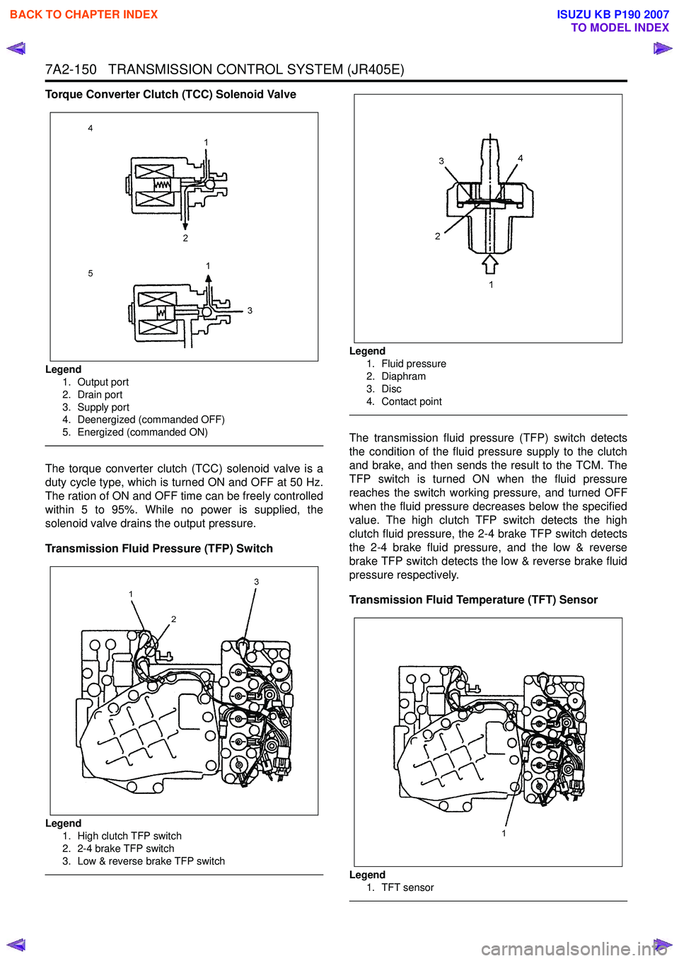
Legend1. Output port
2. Drain port
3. Supply port
4. Deenergized (commanded OFF)
5. Energized (commanded ON)
The torque converter clutch (TCC) solenoid valve is a
duty cycle type, which is turned ON and OFF at 50 Hz.
The ration of ON and OFF time can be freely controlled
within 5 to 95%. While no power is supplied, the
solenoid valve drains the output pressure.
Transmission Fluid Pressure (TFP) Switch
Legend 1. High clutch TFP switch
2. 2-4 brake TFP switch
3. Low & reverse brake TFP switch
Legend
1. Fluid pressure
2. Diaphram
3. Disc
4. Contact point
The transmission fluid pressure (TFP) switch detects
the condition of the fluid pressure supply to the clutch
and brake, and then sends the result to the TCM. The
TFP switch is turned ON when the fluid pressure
reaches the switch working pressure, and turned OFF
when the fluid pressure decreases below the specified
value. The high clutch TFP switch detects the high
clutch fluid pressure, the 2-4 brake TFP switch detects
the 2-4 brake fluid pressure, and the low & reverse
brake TFP switch detects the low & reverse brake fluid
pressure respectively.
Transmission Fluid Temperature (TFT) Sensor
Legend
1. TFT sensor
BACK TO CHAPTER INDEX
TO MODEL INDEX
ISUZU KB P190 2007
Page 4435 of 6020
TRANSMISSION CONTROL SYSTEM (JR405E) 7A2-151
The transmission fluid temperature (TFT) sensor is part
of the harness assembly. The sensor is a variable
resistor and it measures the temperature of the
transmission fluid. When the TFT sensor is cold, the
sensor resistance is high. When the transmission fluid
temperature increases, the sensor resistance
decreases. With high sensor resistance, the TCM
detects a high voltage on the signal circuit. With lower
sensor resistance, the TCM detects a lower voltage on
the signal circuit.
If the fluid temperature increases to 135 °C (275 °F), the
TCM illuminates A/T Oil Temp lamp on the instrument
panel cluster. When the fluid temperature deceases
below 125 °C (257 °F), the lamp goes off.
Transmission Range (TR) Switch
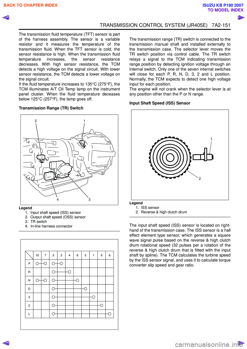
Legend 1. Input shaft speed (ISS) sensor
2. Output shaft speed (OSS) sensor
3. TR switch
4. In-line harness connector
The transmission range (TR) switch is connected to the
transmission manual shaft and installed externally to
the transmission case. The selector lever moves the
TR switch position via control cable. The TR switch
relays a signal to the TCM indicating transmission
range position by detecting ignition voltage through an
internal switch. Only one of the seven internal switches
will close for each P, R, N, D, 3, 2 and L position.
Normally, the TCM expects to detect one high voltage
input for each position.
The engine will not crank when the selector lever is at
any position other than the P or N range.
Input Shaft Speed (ISS) Sensor
Legend 1. ISS sensor
2. Reverse & high clutch drum
The input shaft speed (ISS) sensor is located on right-
hand of the transmission case. The ISS sensor is a hall
effect element type sensor, which generates a square
wave signal pulse based on the reverse & high clutch
drum rotational speed (32 pulses per a rotation of the
reverse & high clutch drum that is fitted with the input
shaft by spline). The TCM calculates the turbine speed
by the ISS sensor signal, and uses it to calculate torque
converter slip speed and gear ratio.
3
1
24
P
R
N
D
3
2
L
10732485196
1
2
BACK TO CHAPTER INDEX
TO MODEL INDEX
ISUZU KB P190 2007
Page 4436 of 6020
7A2-152 TRANSMISSION CONTROL SYSTEM (JR405E)
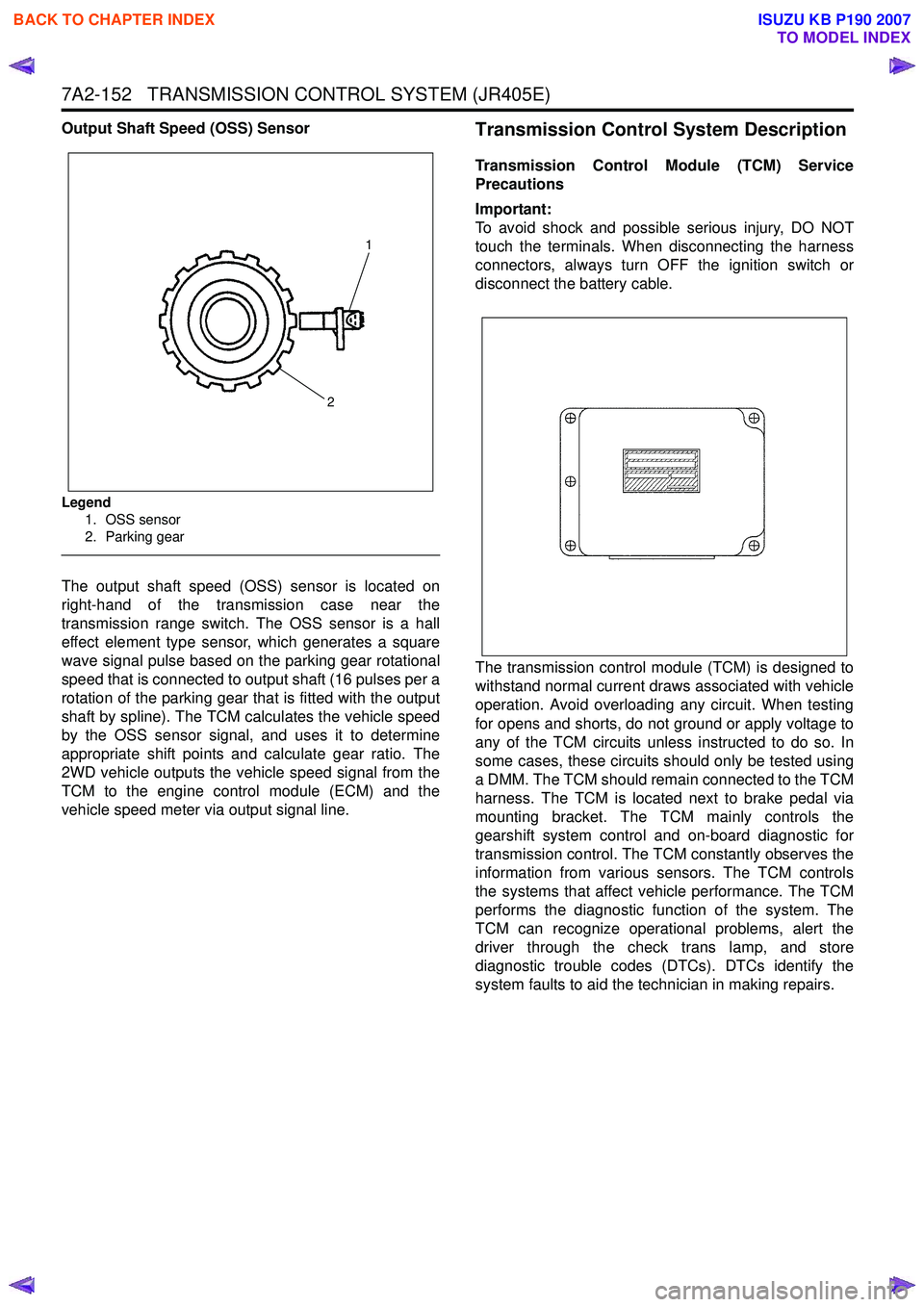
Output Shaft Speed (OSS) Sensor
Legend1. OSS sensor
2. Parking gear
The output shaft speed (OSS) sensor is located on
right-hand of the transmission case near the
transmission range switch. The OSS sensor is a hall
effect element type sensor, which generates a square
wave signal pulse based on the parking gear rotational
speed that is connected to output shaft (16 pulses per a
rotation of the parking gear that is fitted with the output
shaft by spline). The TCM calculates the vehicle speed
by the OSS sensor signal, and uses it to determine
appropriate shift points and calculate gear ratio. The
2WD vehicle outputs the vehicle speed signal from the
TCM to the engine control module (ECM) and the
vehicle speed meter via output signal line.
Transmission Control System Description
Transmission Control Module (TCM) Service
Precautions
Important:
To avoid shock and possible serious injury, DO NOT
touch the terminals. When disconnecting the harness
connectors, always turn OFF the ignition switch or
disconnect the battery cable.
The transmission control module (TCM) is designed to
withstand normal current draws associated with vehicle
operation. Avoid overloading any circuit. When testing
for opens and shorts, do not ground or apply voltage to
any of the TCM circuits unless instructed to do so. In
some cases, these circuits should only be tested using
a DMM. The TCM should remain connected to the TCM
harness. The TCM is located next to brake pedal via
mounting bracket. The TCM mainly controls the
gearshift system control and on-board diagnostic for
transmission control. The TCM constantly observes the
information from various sensors. The TCM controls
the systems that affect vehicle performance. The TCM
performs the diagnostic function of the system. The
TCM can recognize operational problems, alert the
driver through the check trans lamp, and store
diagnostic trouble codes (DTCs). DTCs identify the
system faults to aid the technician in making repairs.
1
2
BACK TO CHAPTER INDEX
TO MODEL INDEX
ISUZU KB P190 2007
Page 4437 of 6020
TRANSMISSION CONTROL SYSTEM (JR405E) 7A2-153
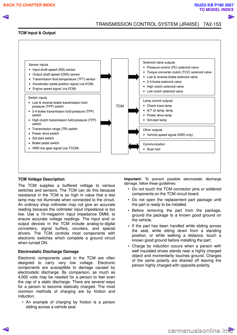
TCM Input & Output
TCM Voltage Description
The TCM supplies a buffered voltage to various
switches and sensors. The TCM can do this because
resistance in the TCM is so high in value that a test
lamp may not illuminate when connected to the circuit.
An ordinary shop voltmeter may not give an accurate
reading because the voltmeter input impedance is too
low. Use a 10-megaohm input impedance DMM, to
ensure accurate voltage readings. The input and/ or
output devices in the TCM include analog-to-digital
converters, signal buffers, counters, and special
drivers. The TCM controls most components with
electronic switches which complete a ground circuit
when turned ON.
Electrostatic Discharge Damage
Electronic components used in the TCM are often
designed to carry very low voltage. Electronic
components are susceptible to damage caused by
electrostatic discharge. By comparison, as much as
4,000 volts may be needed for a person to feel even
the zap of a static discharge. There are several ways
for a person to become statically charged. The most
common methods of charging are by friction and
induction.
• An example of charging by friction is a person sliding across a vehicle seat.
Important: To prevent possible electrostatic discharge
damage, follow these guidelines:
• Do not touch the TCM connector pins or soldered components on the TCM circuit board.
• Do not open the replacement part package until the part is ready to be installed.
• Before removing the part from the package, ground the package to a known good ground on
the vehicle.
• If the part has been handled while sliding across the seat, while sitting down from a standing
position, or while walking a distance, touch a
known good ground before installing the part.
• Charge by induction occurs when a person with well insulated shoes stands near a highly charged
object and momentarily touches ground. Charges
of the same polarity are drained off leaving the
person highly charged with opposite polarity.
Sensor inputs
Input shaft speed (ISS) sensor
Output shaft speed (OSS) sensor
Transmission fluid temperature (TFT) sensor
Accelerator pedal position signal (via ECM)
Engine speed signal (via ECM)
Switch inputs
Low & reverse brake transmission fulid
pressure (TFP) switch
2-4 brake transmission fulid pressure (TFP)
switch
High clutch transmission fulid pressure (TFP)
switch
Transmission range (TR) switch
Power drive switch
3rd start switch
Brake pedal switch
4WD low gear signal (via TCCM)
TCM
Solenoid valve outputs
Pressure control (PC) solenoid valve
Torque converter clutch (TCC) solenoid valve
Low & reverse brake solenoid valve
2-4 brake solenoid valve
High clutch solenoid valve
Low clutch solenoid valve
Other outputsVehicle speed signal (2WD only)
CommunicationScan tool
Lamp control outputsCheck trans lamp
A/T oil temp. lamp
Power drive lamp
3rd start lamp
BACK TO CHAPTER INDEX
TO MODEL INDEX
ISUZU KB P190 2007
Page 4438 of 6020
7A2-154 TRANSMISSION CONTROL SYSTEM (JR405E)
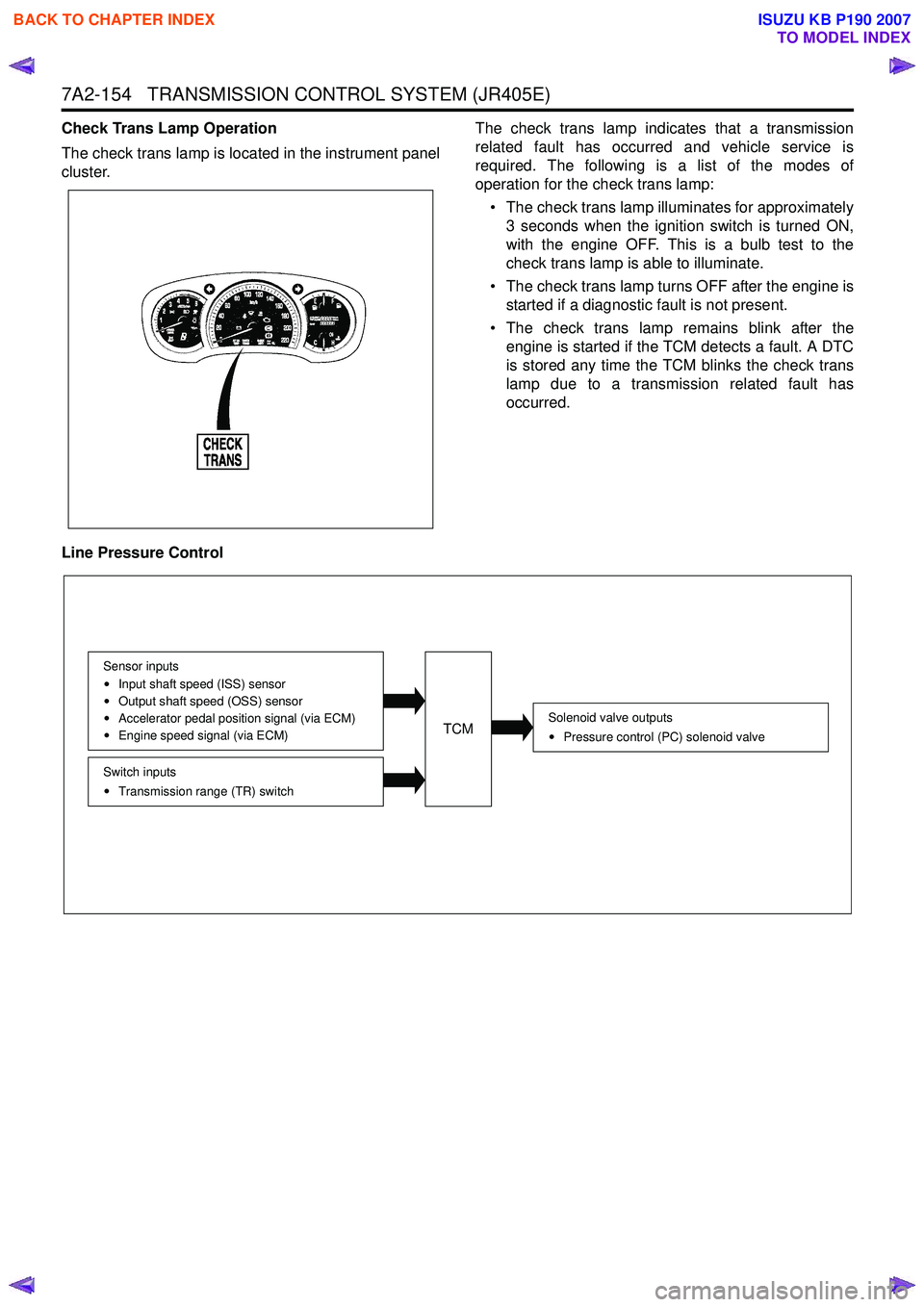
Check Trans Lamp Operation
The check trans lamp is located in the instrument panel
cluster. The check trans lamp indicates that a transmission
related fault has occurred and vehicle service is
required. The following is a list of the modes of
operation for the check trans lamp:
• The check trans lamp illuminates for approximately 3 seconds when the ignition switch is turned ON,
with the engine OFF. This is a bulb test to the
check trans lamp is able to illuminate.
• The check trans lamp turns OFF after the engine is started if a diagnostic fault is not present.
• The check trans lamp remains blink after the engine is started if the TCM detects a fault. A DTC
is stored any time the TCM blinks the check trans
lamp due to a transmission related fault has
occurred.
Line Pressure Control
Solenoid valve outputs Pressure control (PC) solenoid valve
Switch inputsTransmission range (TR) switch
Sensor inputs
Input shaft speed (ISS) sensor
Output shaft speed (OSS) sensor
Accelerator pedal position signal (via ECM)
Engine speed signal (via ECM)TCM
BACK TO CHAPTER INDEX
TO MODEL INDEX
ISUZU KB P190 2007
Page 4440 of 6020
7A2-156 TRANSMISSION CONTROL SYSTEM (JR405E)
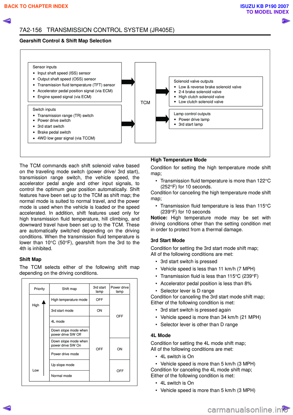
Gearshift Control & Shift Map Selection
The TCM commands each shift solenoid valve based
on the traveling mode switch (power drive/ 3rd start),
transmission range switch, the vehicle speed, the
accelerator pedal angle and other input signals, to
control the optimum gear position automatically. Shift
features have been set up to the TCM as shift map; the
normal mode is suited to normal travel, and the power
mode is used when the vehicle is loaded or the speed
accelerated. In addition, shift features used only for
high transmission fluid temperature, hill climbing, and
downward travel have been set up to the TCM. These
are automatically switched depending on the driving
conditions. When the transmission fluid temperature is
lower than 10 °C (50 °F), gearshift from the 3rd to the
4th is inhibited.
Shift Map
The TCM selects either of the following shift map
depending on the driving conditions. High Temperature Mode
Condition for setting the high temperature mode shift
map;
• Transmission fluid temperature is more than 122 °C
(252 °F) for 10 seconds.
Condition for canceling the high temperature mode shift
map;
• Transmission fluid temperature is less than 115 °C
(239 °F) for 10 seconds
Notice: High temperature mode may be set with
driving conditions other than the setting condition met
in order to protect from a thermal damage.
3rd Start Mode
Condition for setting the 3rd start mode shift map;
All of the following conditions are met:
• 3rd start switch is pressed
• Vehicle speed is less than 11 km/h (7 MPH)
• Transmission fluid is less than 115 °C (239 °F)
• Accelerator pedal position is less than 8%
• Selector lever is D range
Condition for canceling the 3rd start mode shift map;
Either of the following condition is met:
• 3rd start switch is pressed again
• Vehicle speed is more than 34 km/h (21 MPH)
• Selector lever is other than D range
4L Mode
Condition for setting the 4L mode shift map;
All of the following conditions are met:
• 4L switch is On
• Vehicle speed is more than 5 km/h (3 MPH)
Condition for canceling the 4L mode shift map;
Either of the following condition is met:
• 4L switch is On
• Vehicle speed is more than 5 km/h (3 MPH)
TCM
Sensor inputs
Input shaft speed (ISS) sensor
Output shaft speed (OSS) sensor
Transmission fluid temperature (TFT) sensor
Accelerator pedal position signal (via ECM)
Engine speed signal (via ECM)
Switch inputs
Transmission range (TR) switch
Power drive switch
3rd start switch
Brake pedal switch
4WD low gear signal (via TCCM)
Solenoid valve outputs
Low & reverse brake solenoid valve
2-4 brake solenoid valve
High clutch solenoid valve
Low clutch solenoid valve
Lamp control outputs
Power drive lamp
3rd start lamp
OFF
ON
OFF ON OFF
OFF
Low
Priority Shift map 3rd start
lamp Power drive
lamp
High temperature mode
3rd start mode
4L mode
Down slope mode when
power drive SW Off
Down slope mode when
power drive SW On
Power drive mode
Up slope mode
Normal mode
High
BACK TO CHAPTER INDEX
TO MODEL INDEX
ISUZU KB P190 2007
Page 4441 of 6020
TRANSMISSION CONTROL SYSTEM (JR405E) 7A2-157
Down Slope Mode
Condition for setting the down slope mode shift map;
All of the following conditions are met:
• Brake pedal switch is depressed
• Accelerator pedal is released
• Vehicle speed is more than 60 km/h (36 MPH)
• Increment of vehicle speed is more than 1 km/h (1 MPH) per second
• Selector lever is D or 3 range
Condition for canceling the down slope mode shift map;
Either of the following condition is met:
• Accelerator pedal is depressed
• Selector lever is other than D or 3 range Power Drive Mode
When the power drive switch is ON, the TCM switches
shift map to the power drive mode map and performs
gearshift control from 1st to 4th to gain more
acceleration compared with normal mode.
Up Slope Mode
Up slope reasoning value is calculated from the
averaged accelerator pedal angle and the averaged
acceleration. Otherwise, up slope reasoning value is
calculated from the vehicle speed. The TCM selects a
up slope mode when the former is bigger than the
latter.
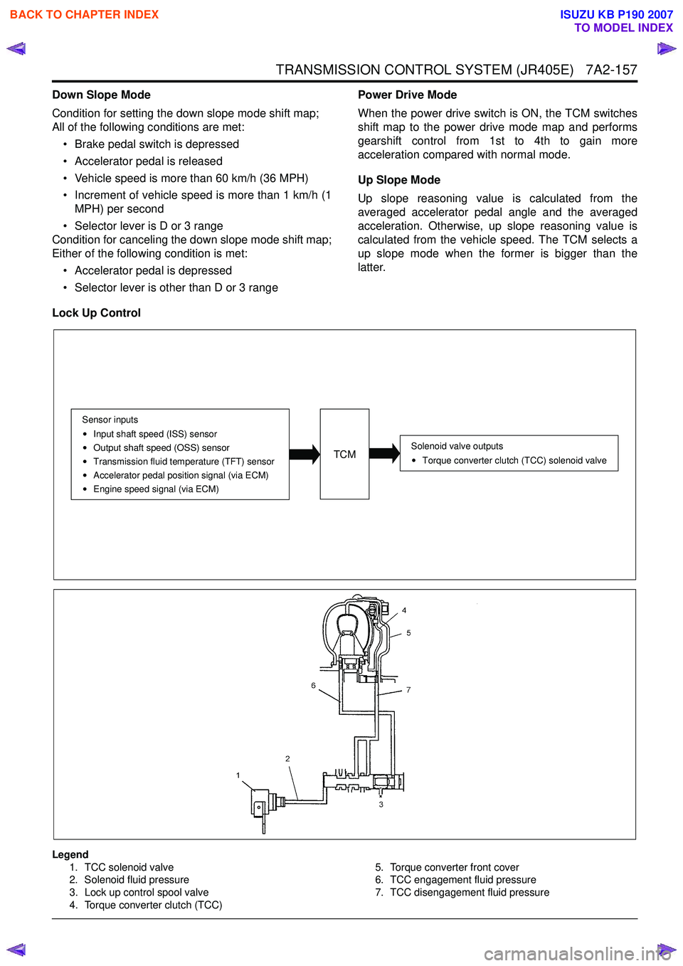
Lock Up Control
Legend 1. TCC solenoid valve
2. Solenoid fluid pressure
3. Lock up control spool valve
4. Torque converter clutch (TCC) 5. Torque converter front cover
6. TCC engagement fluid pressure
7. TCC disengagement fluid pressure
TCM
Sensor inputs
Input shaft speed (ISS) sensor
Output shaft speed (OSS) sensor
Transmission fluid temperature (TFT) sensor
Accelerator pedal position signal (via ECM)
Engine speed signal (via ECM)
Solenoid valve outputsTorque converter clutch (TCC) solenoid valve
BACK TO CHAPTER INDEX
TO MODEL INDEX
ISUZU KB P190 2007