check engine light ISUZU KB P190 2007 Workshop Repair Manual
[x] Cancel search | Manufacturer: ISUZU, Model Year: 2007, Model line: KB P190, Model: ISUZU KB P190 2007Pages: 6020, PDF Size: 70.23 MB
Page 3691 of 6020
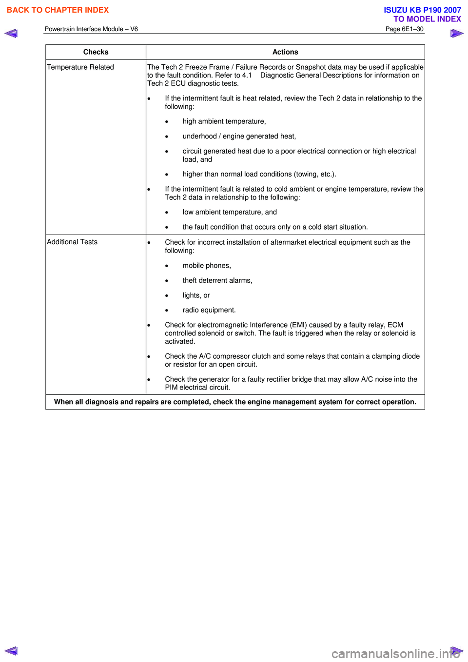
Powertrain Interface Module – V6 Page 6E1–30
Checks Actions
Temperature Related The Tech 2 Freeze Frame / Failure Records or Snapshot data may be used if applicable
to the fault condition. Refer to 4.1 Diagnostic General Descriptions for information on
Tech 2 ECU diagnostic tests.
• If the intermittent fault is heat related, review the Tech 2 data in relationship to the
following:
• high ambient temperature,
• underhood / engine generated heat,
• circuit generated heat due to a poor electrical connection or high electrical
load, and
• higher than normal load conditions (towing, etc.).
• If the intermittent fault is related to cold ambient or engine temperature, review the
Tech 2 data in relationship to the following:
• low ambient temperature, and
• the fault condition that occurs only on a cold start situation.
Additional Tests
• Check for incorrect installation of aftermarket electrical equipment such as the
following:
• mobile phones,
• theft deterrent alarms,
• lights, or
• radio equipment.
• Check for electromagnetic Interference (EMI) caused by a faulty relay, ECM
controlled solenoid or switch. The fault is triggered when the relay or solenoid is
activated.
• Check the A/C compressor clutch and some relays that contain a clamping diode
or resistor for an open circuit.
• Check the generator for a faulty rectifier bridge that may allow A/C noise into the
PIM electrical circuit.
When all diagnosis and repairs are completed, check the engine management system for correct operation.
BACK TO CHAPTER INDEX
TO MODEL INDEX
ISUZU KB P190 2007
Page 3785 of 6020
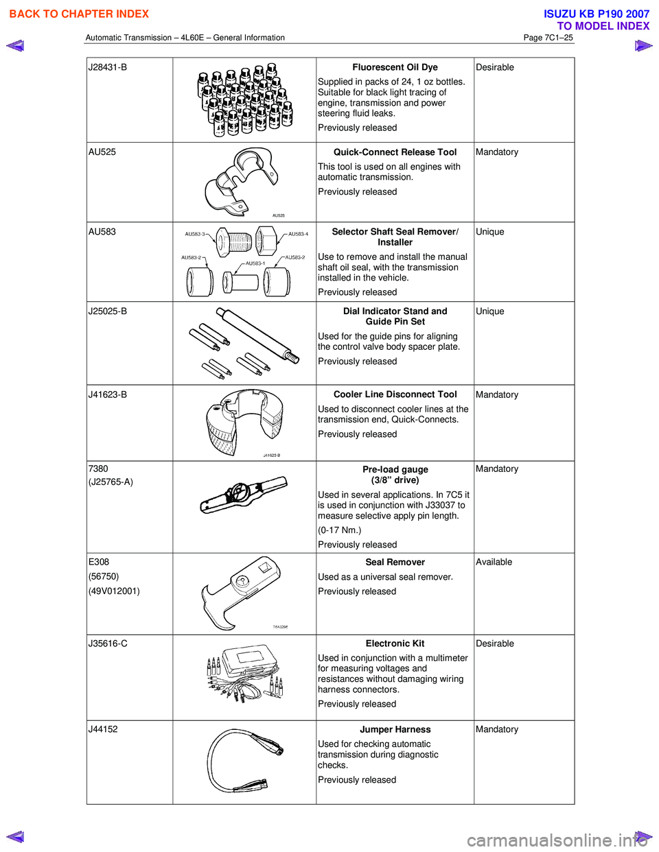
Automatic Transmission – 4L60E – General Information Page 7C1–25
J28431-B
Fluorescent Oil Dye
Supplied in packs of 24, 1 oz bottles.
Suitable for black light tracing of
engine, transmission and power
steering fluid leaks.
Previously released Desirable
AU525
AU525 Quick-Connect Release Tool
This tool is used on all engines with
automatic transmission.
Previously released Mandatory
AU583 Selector Shaft Seal Remover/
Installer
Use to remove and install the manual
shaft oil seal, with the transmission
installed in the vehicle.
Previously released Unique
J25025-B
Dial Indicator Stand and
Guide Pin Set
Used for the guide pins for aligning
the control valve body spacer plate.
Previously released Unique
J41623-B
Cooler Line Disconnect Tool
Used to disconnect cooler lines at the
transmission end, Quick-Connects.
Previously released Mandatory
7380
(J25765-A)
Pre-load gauge
(3/8” drive)
Used in several applications. In 7C5 it
is used in conjunction with J33037 to
measure selective apply pin length.
(0-17 Nm.)
Previously released Mandatory
E308
(56750)
(49V012001)
Seal Remover
Used as a universal seal remover .
Previously released Available
J35616-C
Electronic Kit
Used in conjunction with a multimeter
for measuring voltages and
resistances without damaging wiring
harness connectors.
Previously released Desirable
J44152
Jumper Harness
Used for checking automatic
transmission during diagnostic
checks.
Previously released Mandatory
BACK TO CHAPTER INDEX
TO MODEL INDEX
ISUZU KB P190 2007
Page 3814 of 6020
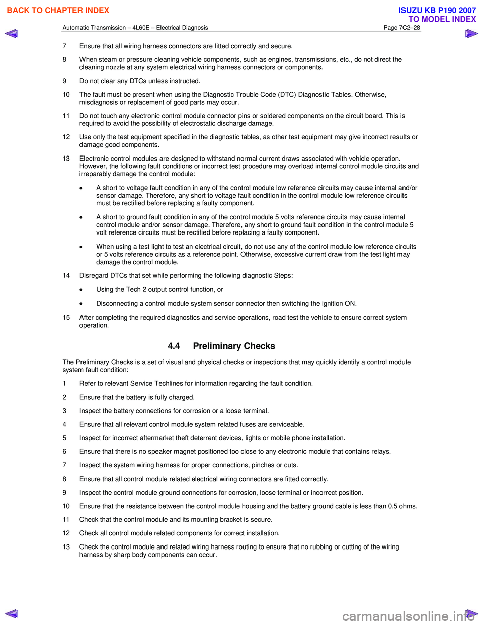
Automatic Transmission – 4L60E – Electrical Diagnosis Page 7C2–28
7 Ensure that all wiring harness connectors are fitted correctly and secure.
8 W hen steam or pressure cleaning vehicle components, such as engines, transmissions, etc., do not direct the cleaning nozzle at any system electrical wiring harness connectors or components.
9 Do not clear any DTCs unless instructed.
10 The fault must be present when using the Diagnostic Trouble Code (DTC) Diagnostic Tables. Otherwise, misdiagnosis or replacement of good parts may occur.
11 Do not touch any electronic control module connector pins or soldered components on the circuit board. This is required to avoid the possibility of electrostatic discharge damage.
12 Use only the test equipment specified in the diagnostic tables, as other test equipment may give incorrect results or damage good components.
13 Electronic control modules are designed to withstand normal current draws associated with vehicle operation. However, the following fault conditions or incorrect test procedure may overload internal control module circuits and
irreparably damage the control module:
• A short to voltage fault condition in any of the control module low reference circuits may cause internal and/or
sensor damage. Therefore, any short to voltage fault condition in the control module low reference circuits
must be rectified before replacing a faulty component.
• A short to ground fault condition in any of the control module 5 volts reference circuits may cause internal
control module and/or sensor damage. Therefore, any short to ground fault condition in the control module 5
volt reference circuits must be rectified before replacing a faulty component.
• W hen using a test light to test an electrical circuit, do not use any of the control module low reference circuits
or 5 volts reference circuits as a reference point. Otherwise, excessive current draw from the test light may
damage the control module.
14 Disregard DTCs that set while performing the following diagnostic Steps:
• Using the Tech 2 output control function, or
• Disconnecting a control module system sensor connector then switching the ignition ON.
15 After completing the required diagnostics and service operations, road test the vehicle to ensure correct system operation.
4.4 Preliminary Checks
The Preliminary Checks is a set of visual and physical checks or inspections that may quickly identify a control module
system fault condition:
1 Refer to relevant Service Techlines for information regarding the fault condition.
2 Ensure that the battery is fully charged.
3 Inspect the battery connections for corrosion or a loose terminal.
4 Ensure that all relevant control module system related fuses are serviceable.
5 Inspect for incorrect aftermarket theft deterrent devices, lights or mobile phone installation.
6 Ensure that there is no speaker magnet positioned too close to any electronic module that contains relays.
7 Inspect the system wiring harness for proper connections, pinches or cuts.
8 Ensure that all control module related electrical wiring connectors are fitted correctly.
9 Inspect the control module ground connections for corrosion, loose terminal or incorrect position.
10 Ensure that the resistance between the control module housing and the battery ground cable is less than 0.5 ohms.
11 Check that the control module and its mounting bracket is secure.
12 Check all control module related components for correct installation.
13 Check the control module and related wiring harness routing to ensure that no rubbing or cutting of the wiring harness by sharp body components can occur.
BACK TO CHAPTER INDEX
TO MODEL INDEX
ISUZU KB P190 2007
Page 3920 of 6020

Automatic Transmission – 4L60E – On-vehicle Servicing Page 7C4–7
NOTE
This will also flush the cooler hose/line
assemblies and cooler with transmission fluid.
7 If the flow rate is satisfactory, reconnect the cooler inlet line to the transmission, refer to 3.17 Transmission Cooler Line/Hose Assemblies.
8 Lower the vehicle, check and top up the transmission fluid to the correct level as required, refer to 2.1 Transmission Fluid.
Flow Rate Test
Do not run the engine any longer than
absolutely necessary, as a fluid level too low
can cause aeration and foaming.
1 Ensure the transmission fluid is at the recommended level or slightly above, refer to 2.1 Transmission Fluid.
2 Disconnect the cooler inlet line at the transmission quick-connect fitting, refer to 3.17 Transmission Cooler Line/Hose Assemblies.
3 Place a suitable size container underneath the disconnected cooler inlet line.
4 W ith the selector lever in the P position, start the engine and observe the fluid flow into the container after all the air bubbles have ceased and a steady flow is evident. Measure the flow rate over 20 seconds and ensure it is within
the specification.
Transmission fluid flow rate specification per 20 Seconds:
Temperature: Ambient ............................................................ 0.7 Litres 86° – 93° C ...................................................... 1.2 Litres
5 If the flow rate is less than the specification, the cause of the low flow rate must be located and rectified. Possible cause could include:
• restricted cooler within the radiator tank,
• kinked or damaged transmission cooler hose/line assemblies, or
• internal transmission fault such as a faulty pump.
6 Reinstall the cooler inlet line to the transmission quick-connect fitting, refer to 3.17 Transmission Cooler Line/Hose Assemblies.
BACK TO CHAPTER INDEX
TO MODEL INDEX
ISUZU KB P190 2007
Page 3956 of 6020
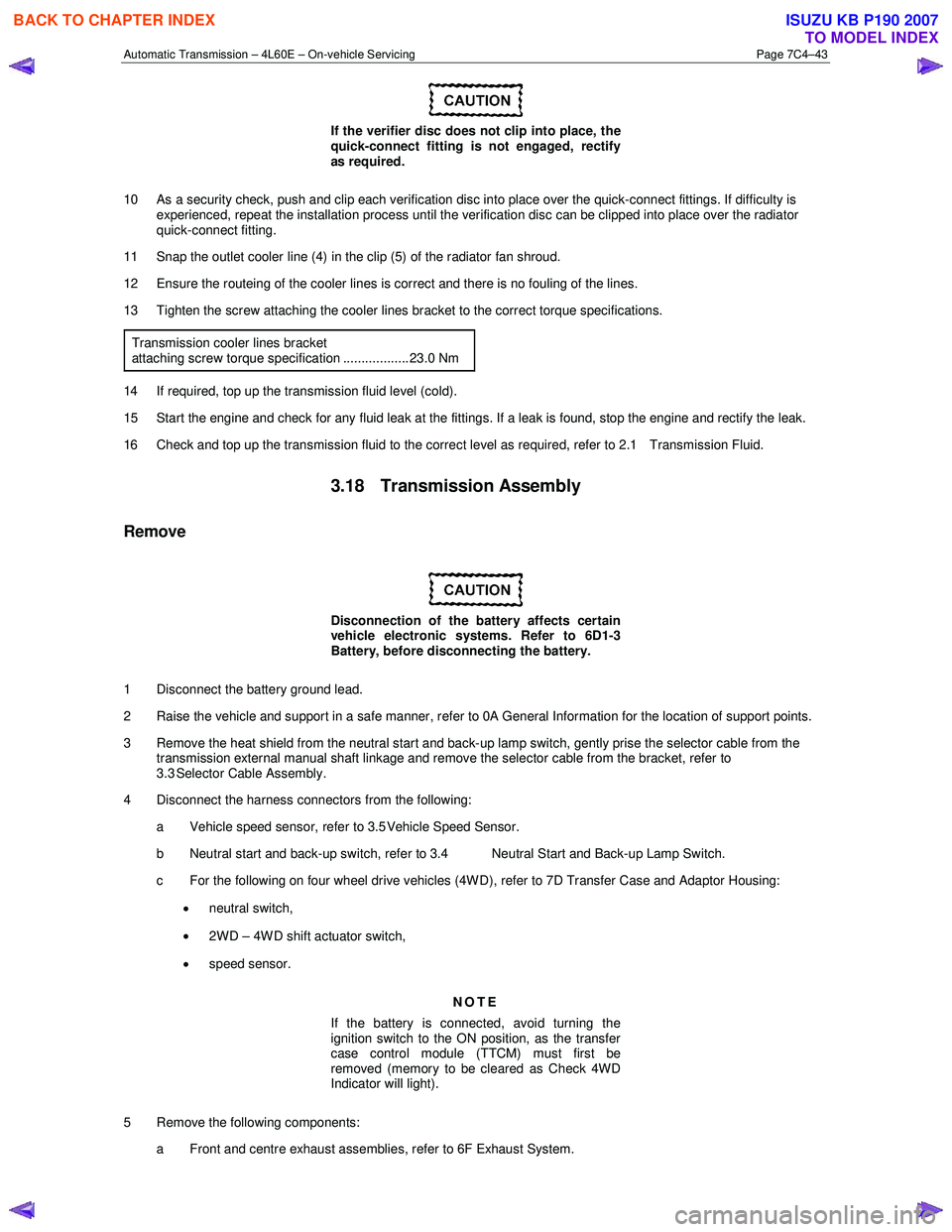
Automatic Transmission – 4L60E – On-vehicle Servicing Page 7C4–43
If the verifier disc does not clip into place, the
quick-connect fitting is not engaged, rectify
as required.
10 As a security check, push and clip each verification disc into place over the quick-connect fittings. If difficulty is experienced, repeat the installation process until the verification disc can be clipped into place over the radiator
quick-connect fitting.
11 Snap the outlet cooler line (4) in the clip (5) of the radiator fan shroud.
12 Ensure the routeing of the cooler lines is correct and there is no fouling of the lines.
13 Tighten the screw attaching the cooler lines bracket to the correct torque specifications.
Transmission cooler lines bracket
attaching screw torque specification .................. 23.0 Nm
14 If required, top up the transmission fluid level (cold).
15 Start the engine and check for any fluid leak at the fittings. If a leak is found, stop the engine and rectify the leak.
16 Check and top up the transmission fluid to the correct level as required, refer to 2.1 Transmission Fluid.
3.18 Transmission Assembly
Remove
Disconnection of the battery affects certain
vehicle electronic systems. Refer to 6D1-3
Battery, before disconnecting the battery.
1 Disconnect the battery ground lead.
2 Raise the vehicle and support in a safe manner, refer to 0A General Information for the location of support points.
3 Remove the heat shield from the neutral start and back-up lamp switch, gently prise the selector cable from the transmission external manual shaft linkage and remove the selector cable from the bracket, refer to
3.3 Selector Cable Assembly.
4 Disconnect the harness connectors from the following:
a Vehicle speed sensor, refer to 3.5 Vehicle Speed Sensor.
b Neutral start and back-up switch, refer to 3.4 Neutral Start and Back-up Lamp Switch.
c For the following on four wheel drive vehicles (4W D), refer to 7D Transfer Case and Adaptor Housing:
• neutral switch,
• 2WD – 4WD shift actuator switch,
• speed sensor.
NOTE
If the battery is connected, avoid turning the
ignition switch to the ON position, as the transfer
case control module (TTCM) must first be
removed (memory to be cleared as Check 4W D
Indicator will light).
5 Remove the following components: a Front and centre exhaust assemblies, refer to 6F Exhaust System.
BACK TO CHAPTER INDEX
TO MODEL INDEX
ISUZU KB P190 2007
Page 3979 of 6020

TRANSMISSION CONTROL SYSTEM (AW30–40LE) 7A2-13
Item Description
Reverse lock out control If the select lever is moved to "R" position during forward driving, the TCM prohibits
reverse driving by turn off the S1 and turn on the S2 for prevention of danger and
protection of the automatic transmission.
1. Enable condition a) Vehicle speed is more than 11km/h (7mph).
2. Disable condition a) Vehicle speed is less than 9km/h (6mph).
b) W hen except "R" position is detected.
Auto cruise mode control If the auto cruise control can’t keep the setting speed like a uphill driving, the TCM selects the auto cruise mode shift pattern for downshifting, thus keeping the vehicle
speed.
W arm-up mode control TCM selects the warm-up mode shift pattern in engine cold condition for improvement of drivability and facilitation of warm-up.
Squat control W hen the TCM detects N→D garage shift, the TCM controls 1-3-1 shift by setting
timer, in order to improve the shift feel at N →D.
Coast down control The TCM switches to the coast down control at the coasting, in order to reduce the
roughness of shifting.
Uphill control W hen the TCM detected uphill, the TCM automatically switches to the uphill mode
in two-stage in proportion to inclination pitch to prevent the busy shifting and to
obtain an enough torque.
Downhill control W hen the TCM detected downhill, the TCM automatically switches to the downhill
mode, and shifts to the 3rd or keeps in the 3rd in order to prevent the vehicle
acceleration. Then, the brake load is reduced by a moderate engine brake and fuel
consumption is improved by the fuel cut.
Line pressure control The TCM controls the impressed current of the pressure control solenoid based on the throttle opening, and regulates suitable throttle pressure.
Engine truque management
control The TCM controls engine torque for improvement of shift quality or durability under
the following conditions.
• Upshift and downshift
• Garageshift
Indicate driving mode function The TCM indicates the following driving mode on instrument panel.
• Power mode
• 3rd start mode
Indicate oil temperature
warning function If the transmission oil temperature sensor senses that transmission oil temperature
is greater than 146 °C (295 °F) , the TCM turns on ATF warning lamp. (The warning
lamp is turned off, if oil temperature is less than 126 °C/ 259 °F .)
Fail-safe function W hen trouble occurs to vehicle sensor and each solenoid, TCM automatically exerts
fail-safe control not to spoil driveability.
• This control is exerted when sensor or actuator is in trouble, while TCM works
normally.
• The "CHECK TRANS" light flashes to alert the driver, and the transmission
must be manually shifted as follows.
Select lever position Gear position
D 4 (Fourth)
3 4 (Fourth)
2 3 (Third)
L 3 (Third)
R Reverse
Shift are firmer to prevent clutch slip and consequent wear. The fault should be
corrected as soon as possible.
BACK TO CHAPTER INDEX
TO MODEL INDEX
ISUZU KB P190 2007
Page 3989 of 6020
TRANSMISSION CONTROL SYSTEM (AW30–40LE) 7A2-23
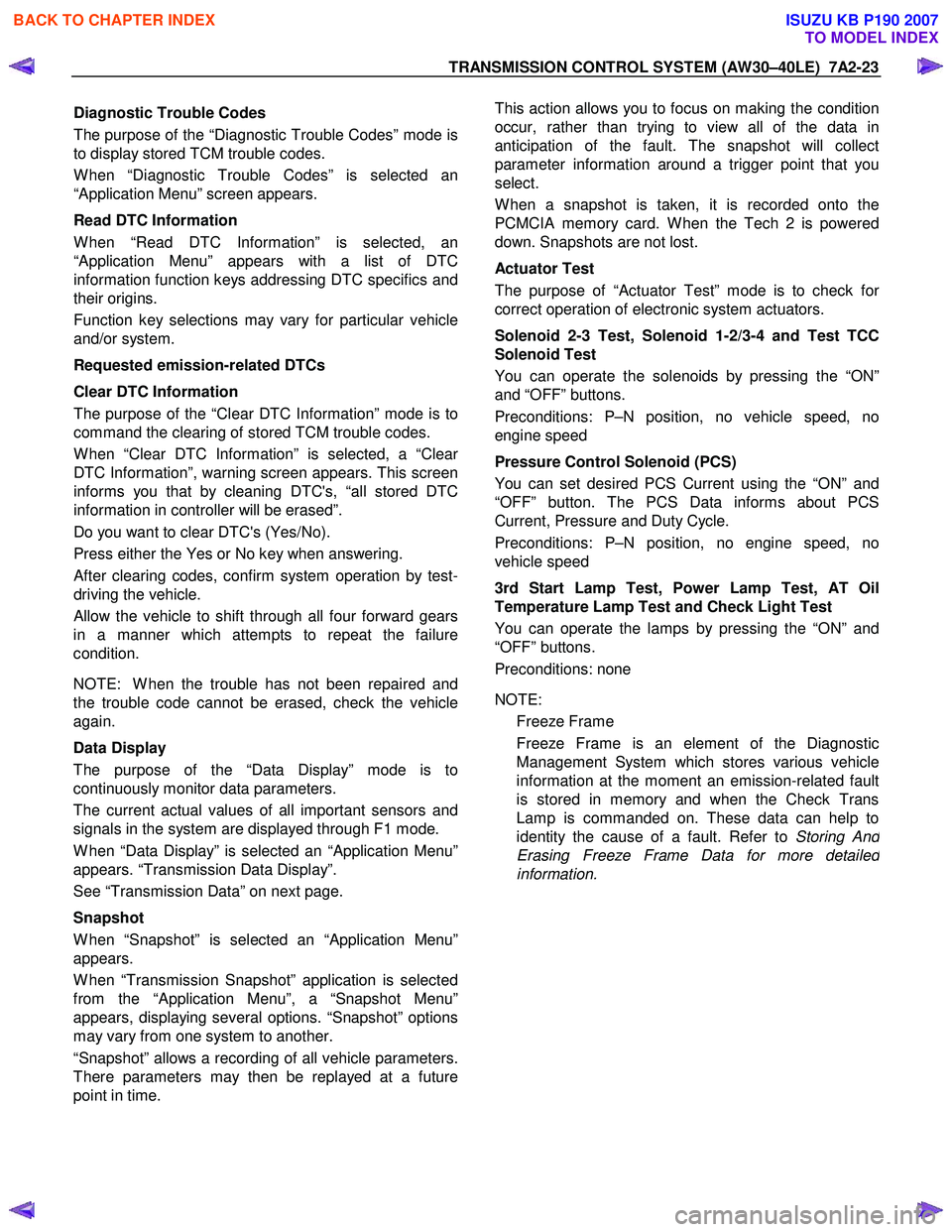
Diagnostic Trouble Codes
The purpose of the “Diagnostic Trouble Codes” mode is
to display stored TCM trouble codes.
W hen “Diagnostic Trouble Codes” is selected an
“Application Menu” screen appears.
Read DTC Information
W hen “Read DTC Information” is selected, an
“Application Menu” appears with a list of DTC
information function keys addressing DTC specifics and
their origins.
Function key selections may vary for particular vehicle
and/or system.
Requested emission-related DTCs
Clear DTC Information
The purpose of the “Clear DTC Information” mode is to
command the clearing of stored TCM trouble codes.
W hen “Clear DTC Information” is selected, a “Clea
r
DTC Information”, warning screen appears. This screen
informs you that by cleaning DTC's, “all stored DTC
information in controller will be erased”.
Do you want to clear DTC's (Yes/No).
Press either the Yes or No key when answering.
After clearing codes, confirm system operation by test-
driving the vehicle.
Allow the vehicle to shift through all four forward gears
in a manner which attempts to repeat the failure
condition.
NOTE: W hen the trouble has not been repaired and
the trouble code cannot be erased, check the vehicle
again.
Data Display
The purpose of the “Data Display” mode is to
continuously monitor data parameters.
The current actual values of all important sensors and
signals in the system are displayed through F1 mode.
W hen “Data Display” is selected an “Application Menu”
appears. “Transmission Data Display”.
See “Transmission Data” on next page.
Snapshot
W hen “Snapshot” is selected an “Application Menu”
appears.
W hen “Transmission Snapshot” application is selected
from the “Application Menu”, a “Snapshot Menu”
appears, displaying several options. “Snapshot” options
may vary from one system to another.
“Snapshot” allows a recording of all vehicle parameters.
There parameters may then be replayed at a future
point in time.
This action allows you to focus on making the condition
occur, rather than trying to view all of the data in
anticipation of the fault. The snapshot will collect
parameter information around a trigger point that you
select.
W hen a snapshot is taken, it is recorded onto the
PCMCIA memory card. W hen the Tech 2 is powered
down. Snapshots are not lost.
Actuator Test
The purpose of “Actuator Test” mode is to check fo
r
correct operation of electronic system actuators.
Solenoid 2-3 Test, Solenoid 1-2/3-4 and Test TCC
Solenoid Test
You can operate the solenoids by pressing the “ON”
and “OFF” buttons.
Preconditions: P–N position, no vehicle speed, no
engine speed
Pressure Control Solenoid (PCS)
You can set desired PCS Current using the “ON” and
“OFF” button. The PCS Data informs about PCS
Current, Pressure and Duty Cycle.
Preconditions: P–N position, no engine speed, no
vehicle speed
3rd Start Lamp Test, Power Lamp Test, AT Oil
Temperature Lamp Test and Check Light Test
You can operate the lamps by pressing the “ON” and
“OFF” buttons.
Preconditions: none
NOTE: Freeze Frame
Freeze Frame is an element of the Diagnostic
Management System which stores various vehicle
information at the moment an emission-related fault
is stored in memory and when the Check Trans
Lamp is commanded on. These data can help to
identity the cause of a fault. Refer to Storing An
d
Erasing Freeze Frame Data for more detaile
d
information.
BACK TO CHAPTER INDEX
TO MODEL INDEX
ISUZU KB P190 2007
Page 3990 of 6020

7A2-24 TRANSMISSION CONTROL SYSTEM (AW30–40LE)
TRANSMISSION DATA
Scan Tool Parameter Units Displayed Typical Data Value at Engine Idle
Operating Conditions: Engine idling/ Engine coolant temperature is between 75 to 85 °C(167 to 185 °F)/
Accelerator pedal is constant/ Neutral or Park/ Accessories OFF/ Vehicle located at sea level
Engine Coolant temperature °C/ °F 75 to 85°C (167 to 185 °F)
Engine Speed RPM 700
Vehicle Speed Km/h / MPH 0
Ignition Voltage V 13.6
Accelerator Pedal Position Signal % 0
Throttle Position % 0
Accelerator Pedal Position Signal
During Cruise Control % 0
Cruise Control
Inactive / Active Inactive
Cruise Control OD Cancel Request ON / OFF OFF
Engine W arm Up Cycle Achieved FALSE / TRUE FALSE
Transmission Shift in Progress Inactive / Active Inactive
Garage Shift Control Inactive / Active Inactive
MIL Request Command ON / OFF OFF
Transmission Check Light ON / OFF OFF
Transmission Oil Temperature Lamp ON / OFF OFF
Power Drive Lamp ON / OFF OFF
3rd Start Lamp ON / OFF OFF
Transmission Fluid Temperature
°C/ °F 70 to 80°C (158 to 176 °F)
AT Input Speed RPM 625
AT Output Speed RPM 0
Transmission Range Park / Reverse /
Neutral / Drive 4 / Drive 3 / Drive 2 / Drive 1 Park
TR Switch P
ON / OFF ON
TR Switch R ON / OFF OFF
TR Switch N ON / OFF OFF
TR Switch D ON / OFF OFF
TR Switch 3 ON / OFF OFF
TR Switch 2 ON / OFF OFF
TR Switch L ON / OFF OFF
Diagnostic Switch Open / Close Open
Brake Pedal Switch ON / OFF OFF
Power Drive Switch ON / OFF OFF
3rd Start Switch ON / OFF OFF
4 W heel Drive Low ON / OFF OFF
Shift Solenoid 1 Command ON / OFF ON
Shift Solenoid 2 Command ON / OFF OFF
TCC Solenoid Engaged / Disengaged Disengaged
Downhill Mode Inactive / Active Inactive
Active Shift Mode Normal Mode /
Power Mode /
3rd Gear Start /
Transfer 4L MODE Hot 1 / Hot 2 /
UPHILL MODE 1 /
UPHILL MODE 2 / Cruise MODE /
W arm Up MODE Normal Mode
Estimated Gear Ratio
:1 7.97 : 1
BACK TO CHAPTER INDEX
TO MODEL INDEX
ISUZU KB P190 2007
Page 4007 of 6020
TRANSMISSION CONTROL SYSTEM (AW30–40LE) 7A2-41
• All of the following conditions are met.
- Device Control is not operating
- Disable Normal Communication Service is receiving enable
- DTC Clear is not operating
Condition For Setting The DTC
W hen the TCM detects following conditions at 20 times
continuously.
• Ignition voltage is less than 9 volts for 1 second o
r
more continuously. (DTC P0562)
• Ignition voltage is more than 18 volts for 1 second o
r
more continuously. (DTC P0563)
Action Taken When The DTC Sets
• DTC stored.
Conditions For Clearing The DTC
• The DTC can be cleared from the TCM history by
using a scan tool.
• The DTC will be cleared from history when the
vehicle has achieved 40 warm-up cycles without a
failure reported.
•
After more than 1 second has elapsed after the
ignition key has been turned “ON”, short between
No.11 and No.4 (ground) of DLC (Data Link
Connector). Then, after 1 second, but within 6
seconds, discontinue shorting.
Diagnostic Aids
•
Inspect the wiring for poor electrical connection at the
TCM. Look for possible bent, backed out, deformed
or damaged terminals. Check for weak terminal
tension as well. Also check for a chafed wire that
could short to bare metal or other wiring.
Inspect for a broken wire inside the insulation.
• W hen diagnosing for a possible intermittent short o
r
open condition, move the wiring harness while
observing test equipment for a change.
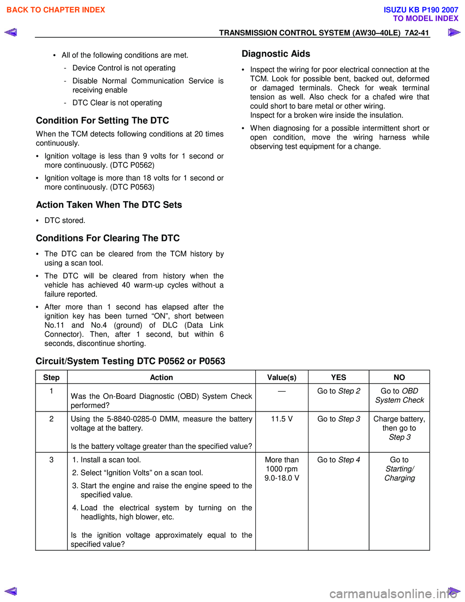
Circuit/System Testing DTC P0562 or P0563
Step Action Value(s) YES NO
1
W as the On-Board Diagnostic (OBD) System Check
performed? — Go to
Step 2 Go to OBD
System Check
2 Using the 5-8840-0285-0 DMM, measure the battery voltage at the battery.
Is the battery voltage greater than the specified value? 11.5 V Go to
Step 3 Charge battery,
then go to Step 3
3 1. Install a scan tool.
2. Select “Ignition Volts” on a scan tool.
3. Start the engine and raise the engine speed to the specified value.
4. Load the electrical system by turning on the headlights, high blower, etc.
Is the ignition voltage approximately equal to the
specified value? More than
1000 rpm
9.0-18.0 V Go to
Step 4 Go to
Starting/
Charging
BACK TO CHAPTER INDEX
TO MODEL INDEX
ISUZU KB P190 2007
Page 4317 of 6020
TRANSMISSION CONTROL SYSTEM (JR405E) 7A2-33
DTC P0560 (Flash Code 16)
Circuit Description
The TCM monitors the ignition voltage on the ignition
feed terminal to make sure that the voltage stays within
the proper range. If the TCM detects an excessively
low ignition voltage, this DTC will set.
Condition for Running the DTC • The ignition switch is ON.
• The engine speed is more than 1000 RPM.
Condition for Setting the DTC • The TCM detects that the ignition voltage feed circuit is less than 10 volts for 1 second.
Action Taken When the DTC Sets • The TCM blinks the Check Trans lamp when the diagnostic runs and fails.
During the vehicle running;
• The TCM holds the last gear position when the diagnostic runs and fails.
• The TCM inhibits lock up control. After the vehicle stopped;
• The TCM stops all shift solenoid valves and fixes to the 3rd gear. If a fail-safe valve problem is
detected, the shift solenoid valves are not stopped
but gear is fixed to the 3rd gear.
• The TCM stops PC solenoid valve.
Condition for Clearing the DTC • The TCM turns OFF the Check Trans lamp when the diagnostic runs and does not fail.
• A current DTC clears when the diagnostic runs and does not fail.
Diagnostic Aids • A charging system problem may set this DTC.
• The weakened battery may set this DTC.
Schematic Reference: Transmission Controls
Schematics
Connector End View Reference: Transmission
Controls Connector End Views or TCM Connector End
Views
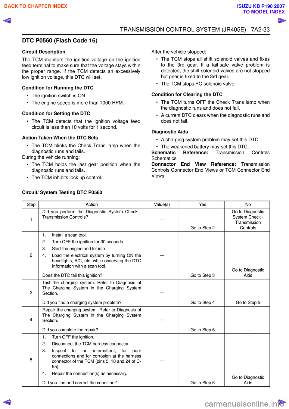
Circuit/ System Testing DTC P0560
Step Action Value(s)Yes No
1 Did you perform the Diagnostic System Check -
Transmission Controls? —
Go to Step 2 Go to Diagnostic
System Check -
Transmission Controls
2 1. Install a scan tool.
2. Turn OFF the ignition for 30 seconds.
3. Start the engine and let idle.
4. Load the electrical system by turning ON the headlights, A/C, etc. while observing the DTC
Information with a scan tool.
Does the DTC fail this ignition? —
Go to Step 3 Go to Diagnostic
Aids
3 Test the charging system. Refer to Diagnosis of
The Charging System in the Charging System
Section.
Did you find a charging system problem? —
Go to Step 4 Go to Step 5
4 Repair the charging system. Refer to Diagnosis of
The Charging System in the Charging System
Section.
Did you complete the repair? —
Go to Step 6 —
5 1. Turn OFF the ignition.
2. Disconnect the TCM harness connector.
3. Inspect for an intermittent, for poor connections and for corrosion at the harness
connector of the TCM (pins 5, 18 and 24 of C-
95).
4. Repair the connection(s) as necessary.
Did you find and correct the condition? —
Go to Step 6 Go to Diagnostic
Aids
BACK TO CHAPTER INDEX
TO MODEL INDEX
ISUZU KB P190 2007