check engine light ISUZU KB P190 2007 Workshop Manual Online
[x] Cancel search | Manufacturer: ISUZU, Model Year: 2007, Model line: KB P190, Model: ISUZU KB P190 2007Pages: 6020, PDF Size: 70.23 MB
Page 2418 of 6020
6E–248 ENGINE DRIVEABILITY AND EMISSIONS
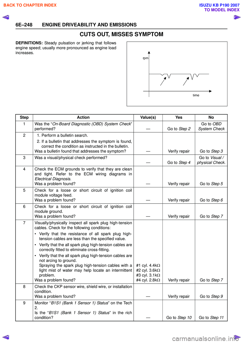
CUTS OUT, MISSES SYMPTOM
DEFINITIONS: Steady pulsation or jerking that follows
engine speed; usually more pronounced as engine load
increases.
Step Action Value(s) Yes No
1 Was the “ On-Board Diagnostic (OBD) System Check ”
performed? — Go to Step 2Go to
OBD
System Check
2 1. Perform a bulletin search. 2. If a bulletin that addresses the symptom is found,correct the condition as instructed in the bulletin.
Was a bulletin found that addresses the symptom? — Verify repair Go to Step 3
3 Was a visual/physical check performed? —Go to Step 4Go to
Visual /
physical Check .
4 Check the ECM grounds to verify that they are clean and tight. Refer to the ECM wiring diagrams in
Electrical Diagnosis .
Was a problem found? — Verify repair Go to Step 5
5 Check for a loose or short circuit of ignition coil module voltage feed.
Was a problem found? — Verify repair Go to Step 6
6 Check for a loose or short circuit of ignition coil module ground.
Was a problem found? — Verify repair Go to Step 7
7 Visually/physically inspect all spark plug high-tension cables. Check for the following conditions:
• Verify that the resistance of all spark plug high- tension cables are less than the specified value.
• Verify that the all spark plug high-tension cables are correctly fitted to eliminate cross-fitting.
• Verify that the all spark plug high-tension cables are not arcing to ground.
Spraying the spark plug high-tension cables with a
light mist of water may help locate an intermittent
problem.
Was a problem found? #1 cyl. 4.4k
Ω
#2 cyl. 3.6k Ω
#3 cyl. 3.1k Ω
#4 cyl. 2.8k ΩVerify repair Go to Step 7
8 Check the CKP sensor wire, shield wire, or installation condition.
Was a problem found? — Verify repair Go to Step 9
9 Monitor “ B1S1 (Bank 1 Sensor 1) Status ” on the Tech
2.
Is the “ B1S1 (Bank 1 Sensor 1) Status ” in the rich
condition? — Go to Step 10Go to Step 11
BACK TO CHAPTER INDEX
TO MODEL INDEX
ISUZU KB P190 2007
Page 2432 of 6020
6E–262 ENGINE DRIVEABILITY AND EMISSIONS
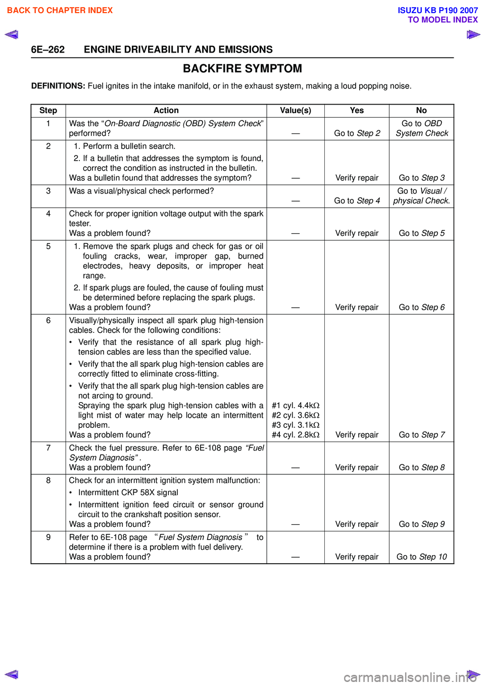
BACKFIRE SYMPTOM
DEFINITIONS: Fuel ignites in the intake manifold, or in the exhaust system, making a loud popping noise.
Step Action Value(s) Yes No
1 Was the “ On-Board Diagnostic (OBD) System Check ”
performed? — Go to Step 2Go to
OBD
System Check
2 1. Perform a bulletin search. 2. If a bulletin that addresses the symptom is found,correct the condition as instructed in the bulletin.
Was a bulletin found that addresses the symptom? — Verify repair Go to Step 3
3 Was a visual/physical check performed? —Go to Step 4Go to
Visual /
physical Check .
4 Check for proper ignition voltage output with the spark tester.
Was a problem found? — Verify repair Go to Step 5
5 1. Remove the spark plugs and check for gas or oil fouling cracks, wear, improper gap, burned
electrodes, heavy deposits, or improper heat
range.
2. If spark plugs are fouled, the cause of fouling must be determined before replacing the spark plugs.
Was a problem found? — Verify repair Go to Step 6
6 Visually/physically inspect all spark plug high-tension cables. Check for the following conditions:
• Verify that the resistance of all spark plug high- tension cables are less than the specified value.
• Verify that the all spark plug high-tension cables are correctly fitted to eliminate cross-fitting.
• Verify that the all spark plug high-tension cables are not arcing to ground.
Spraying the spark plug high-tension cables with a
light mist of water may help locate an intermittent
problem.
Was a problem found? #1 cyl. 4.4k
Ω
#2 cyl. 3.6k Ω
#3 cyl. 3.1k Ω
#4 cyl. 2.8k ΩVerify repair Go to Step 7
7 Check the fuel pressure. Refer to 6E-108 page “Fuel
System Diagnosis” .
Was a problem found? — Verify repair Go to Step 8
8 Check for an intermittent ignition system malfunction: • Intermittent CKP 58X signal
• Intermittent ignition feed circuit or sensor ground circuit to the crankshaft position sensor.
Was a problem found? — Verify repair Go to Step 9
9 Refer to 6E-108 page “Fuel System Diagnosis ” to
determine if there is a problem with fuel delivery.
Was a problem found? — Verify repair Go to Step 10
BACK TO CHAPTER INDEX
TO MODEL INDEX
ISUZU KB P190 2007
Page 2481 of 6020
Engine Mechanical – V6 Page 6A1–2
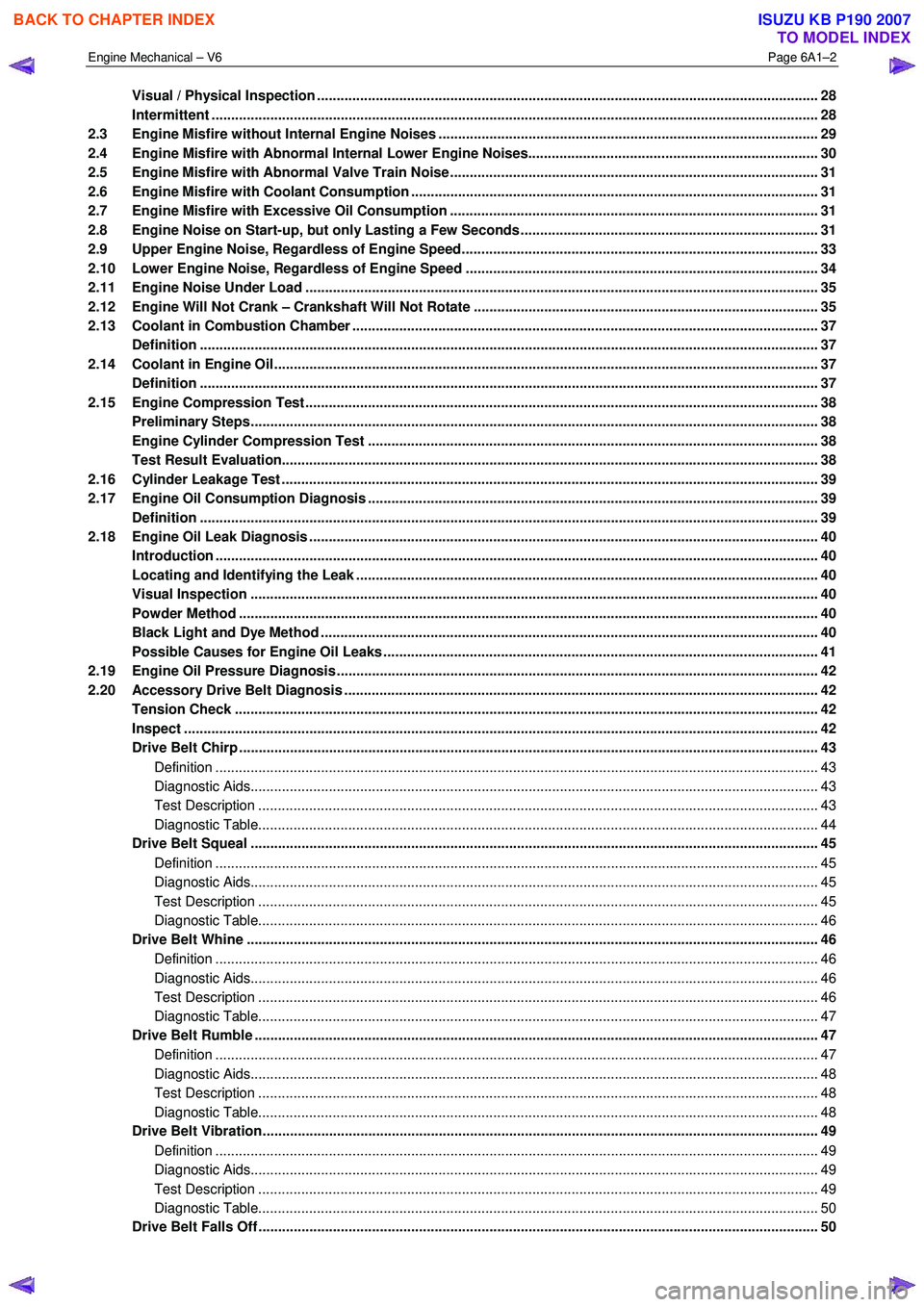
Visual / Physical Inspection ................................................................................................................................ 28
Intermittent ........................................................................................................................................................... 28
2.3 Engine Misfire without Internal Engine Noises .................................................................................. ............... 29
2.4 Engine Misfire with Abnormal Internal Lower Engine Noises...................................................................... .... 30
2.5 Engine Misfire with Abnormal Valve Train Noise .............................................................................................. 31
2.6 Engine Misfire with Coolant Consumption ........................................................................................................ 31
2.7 Engine Misfire with Excessive Oil Consumption .................................................................................. ............ 31
2.8 Engine Noise on Start-up, but only Lasting a Few Seconds ....................................................................... ..... 31
2.9 Upper Engine Noise, Regardless of Engine Speed........................................................................................... 33
2.10 Lower Engine Noise, Regardless of Engine Speed ................................................................................. ......... 34
2.11 Engine Noise Under Load ................................................................................................................................... 35
2.12 Engine Will Not Crank – Crankshaft Will Not Rotate ............................................................................. ........... 35
2.13 Coolant in Combustion Chamber ....................................................................................................................... 37
Definition .............................................................................................................................................................. 37
2.14 Coolant in Engine Oil.......................................................................................................... ................................. 37
Definition .............................................................................................................................................................. 37
2.15 Engine Compression Test ........................................................................................................ ........................... 38
Preliminary Steps................................................................................................................................................. 38
Engine Cylinder Compression Test ............................................................................................... .................... 38
Test Result Evaluation......................................................................................................................................... 38
2.16 Cylinder Leakage Test .......................................................................................................... ............................... 39
2.17 Engine Oil Consumption Diagnosis ............................................................................................... .................... 39
Definition .............................................................................................................................................................. 39
2.18 Engine Oil Leak Diagnosis ...................................................................................................... ............................ 40
Introduction .......................................................................................................................................................... 40
Locating and Identifying the Leak .............................................................................................. ........................ 40
Visual Inspection ................................................................................................................................................. 40
Powder Method .................................................................................................................. .................................. 40
Black Light and Dye Method ..................................................................................................... .......................... 40
Possible Causes for Engine Oil Leaks ........................................................................................... .................... 41
2.19 Engine Oil Pressure Diagnosis ........................................................................................................................... 42
2.20 Accessory Drive Belt Diagnosis ................................................................................................. ........................ 42
Tension Check ..................................................................................................................................................... 42
Inspect .................................................................................................................................................................. 42
Drive Belt Chirp .................................................................................................................................................... 43
Definition .......................................................................................................................................................... 43
Diagnostic Aids................................................................................................................................................. 43
Test Description ............................................................................................................... ................................ 43
Diagnostic Table............................................................................................................................................... 44
Drive Belt Squeal .............................................................................................................. ................................... 45
Definition .......................................................................................................................................................... 45
Diagnostic Aids................................................................................................................................................. 45
Test Description ............................................................................................................... ................................ 45
Diagnostic Table............................................................................................................................................... 46
Drive Belt Whine ............................................................................................................... ................................... 46
Definition .......................................................................................................................................................... 46
Diagnostic Aids................................................................................................................................................. 46
Test Description ............................................................................................................... ................................ 46
Diagnostic Table............................................................................................................................................... 47
Drive Belt Rumble .............................................................................................................. .................................. 47
Definition .......................................................................................................................................................... 47
Diagnostic Aids................................................................................................................................................. 48
Test Description ............................................................................................................... ................................ 48
Diagnostic Table............................................................................................................................................... 48
Drive Belt Vibration........................................................................................................... ................................... 49
Definition .......................................................................................................................................................... 49
Diagnostic Aids................................................................................................................................................. 49
Test Description ............................................................................................................... ................................ 49
Diagnostic Table............................................................................................................................................... 50
Drive Belt Falls Off ........................................................................................................... .................................... 50
BACK TO CHAPTER INDEX
TO MODEL INDEX
ISUZU KB P190 2007
Page 2509 of 6020
Engine Mechanical – V6 Page 6A1–30
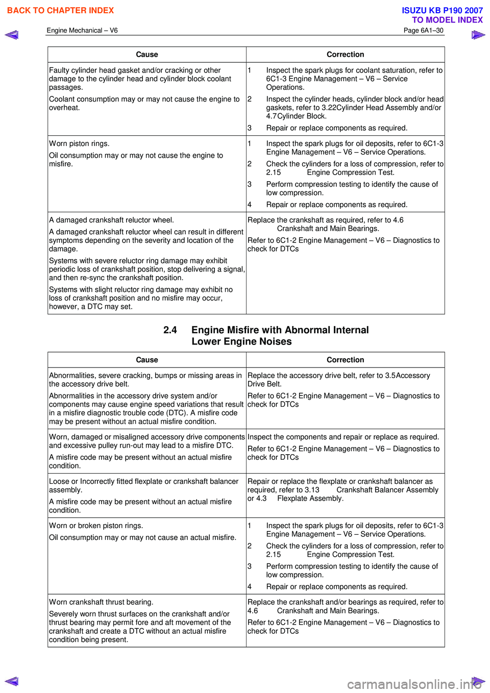
Cause Correction
Faulty cylinder head gasket and/or cracking or other
damage to the cylinder head and cylinder block coolant
passages.
Coolant consumption may or may not cause the engine to
overheat. 1 Inspect the spark plugs for coolant saturation, refer to
6C1-3 Engine Management – V6 – Service
Operations.
2 Inspect the cylinder heads, cylinder block and/or head gaskets, refer to 3.22 Cylinder Head Assembly and/or
4.7 Cylinder Block.
3 Repair or replace components as required.
W orn piston rings.
Oil consumption may or may not cause the engine to
misfire. 1 Inspect the spark plugs for oil deposits, refer to 6C1-3
Engine Management – V6 – Service Operations.
2 Check the cylinders for a loss of compression, refer to 2.15 Engine Compression Test.
3 Perform compression testing to identify the cause of low compression.
4 Repair or replace components as required.
A damaged crankshaft reluctor wheel.
A damaged crankshaft reluctor wheel can result in different
symptoms depending on the severity and location of the
damage.
Systems with severe reluctor ring damage may exhibit
periodic loss of crankshaft position, stop delivering a signal,
and then re-sync the crankshaft position.
Systems with slight reluctor ring damage may exhibit no
loss of crankshaft position and no misfire may occur,
however, a DTC may set. Replace the crankshaft as required, refer to 4.6
Crankshaft and Main Bearings.
Refer to 6C1-2 Engine Management – V6 – Diagnostics to
check for DTCs
2.4 Engine Misfire with Abnormal Internal Lower Engine Noises
Cause Correction
Abnormalities, severe cracking, bumps or missing areas in
the accessory drive belt.
Abnormalities in the accessory drive system and/or
components may cause engine speed variations that result
in a misfire diagnostic trouble code (DTC). A misfire code
may be present without an actual misfire condition. Replace the accessory drive belt, refer to 3.5
Accessory
Drive Belt.
Refer to 6C1-2 Engine Management – V6 – Diagnostics to
check for DTCs
W orn, damaged or misaligned accessory drive components
and excessive pulley run-out may lead to a misfire DTC.
A misfire code may be present without an actual misfire
condition. Inspect the components and repair or replace as required.
Refer to 6C1-2 Engine Management – V6 – Diagnostics to
check for DTCs
Loose or Incorrectly fitted flexplate or crankshaft balancer
assembly.
A misfire code may be present without an actual misfire
condition. Repair or replace the flexplate or crankshaft balancer as
required, refer to 3.13 Crankshaft Balancer Assembly
or 4.3 Flexplate Assembly.
W orn or broken piston rings.
Oil consumption may or may not cause an actual misfire. 1 Inspect the spark plugs for oil deposits, refer to 6C1-3
Engine Management – V6 – Service Operations.
2 Check the cylinders for a loss of compression, refer to 2.15 Engine Compression Test.
3 Perform compression testing to identify the cause of low compression.
4 Repair or replace components as required.
W orn crankshaft thrust bearing.
Severely worn thrust surfaces on the crankshaft and/or
thrust bearing may permit fore and aft movement of the
crankshaft and create a DTC without an actual misfire
condition being present. Replace the crankshaft and/or bearings as required, refer to
4.6 Crankshaft and Main Bearings.
Refer to 6C1-2 Engine Management – V6 – Diagnostics to
check for DTCs
BACK TO CHAPTER INDEX
TO MODEL INDEX
ISUZU KB P190 2007
Page 2514 of 6020
Engine Mechanical – V6 Page 6A1–35
2.11 Engine Noise Under Load
NOTE
A cold piston knock which disappears in
approximately 1.5 minutes from start up, should
be considered acceptable. A cold engine knock
usually disappears when the specific cylinder’s
secondary ignition circuit is grounded out during
diagnosis.
A light rattle/tapping noise may indicate a valve train/upper engine concern, while a low rumble/knocking may indicate a
crankshaft, piston or lower engine concern.
Cause Correction
Low oil pressure. 1 Perform an oil pressure test, refer to 2.19
Engine Oil Pressure Diagnosis.
2 Repair or replace the engine oil pump as required, refer to 3.17 Oil Pump Assembly.
Detonation or spark knock. Confirm the correct operation of the ignition system, refer to
6C1-2 Engine Management – V6 – Diagnostics.
Loose torque converter bolts. Inspect and tighten the torque converter bolts to the correct
torque specification, refer to 7C1 Automatic – 4L60E –
General Information – 4L60E – General Information.
Cracked flexplate. Replace the flywheel/flex-plate as required, refer to 4.3
Flexplate Assembly.
Excessive connecting rod bearing clearance. Inspect the connecting rod, crankshaft and bearings and
repair/replace components as required, refer to 4.5
Pistons, Pins, Rings, Connecting Rods and Big-
end Bearings and 4.6 Crankshaft and Main Bearings.
Excessive crankshaft bearing clearance Inspect the crankshaft, cylinder block journals, main
bearings and main bearing caps and repair/replace
components as required, refer to 4.6 Crankshaft
and Main Bearings and 4.7Cylinder Block.
2.12 Engine Will Not Crank – Crankshaft Will Not Rotate
Cause Correction
Seized accessory drive system component. 1 Remove the accessory drive belt, refer to 3.5
Accessory Drive Belt.
2 Rotate the crankshaft by hand at the balancer pulley or flywheel.
3 Repair or replace accessory drive system components as required.
Hydraulically locked cylinder caused by:
• coolant in cylinder,
• oil in cylinder, or
• fuel in cylinder. 1 Remove the spark plugs and check for fluid, refer to
6C1-3 Engine Management – V6 – Service
Operations.
2 Inspect for broken head gasket/s.
3 Inspect for cracked engine block or cylinder head.
4 Inspect for sticking fuel injector.
5 Repair or replace components as required.
Seized torque converter. 1 Remove the torque converter bolts, refer to 7C1
Automatic – 4L60E – General Information – 4L60E –
General Information.
2 Rotate the crankshaft by hand at the balancer pulley or flywheel.
3 Repair or replace torque converter as required.
BACK TO CHAPTER INDEX
TO MODEL INDEX
ISUZU KB P190 2007
Page 2519 of 6020
Engine Mechanical – V6 Page 6A1–40
Cause Correction
W orn valve guides and or valve stems. Inspect and repair valves and valve guides as required,
refer to 3.22 Cylinder Head Assembly.
W orn or damaged valve stem oil seal. Replace valve stem oil seals as required, refer to 3.22
Cylinder Head Assembly.
Piston rings broken, worn or not seated correctly. Allowing adequate time for the piston rings to seat correctly,
replace piston rings as required, refer to 4.5 Pistons, Pins,
Rings, Connecting Rods and Big-end Bearings.
Piston rings incorrectly installed or not matched to cylinder
bore oversize. Replace piston rings as required, refer to 4.5 Pistons, Pins,
Rings, Connecting Rods and Big-end Bearings.
2.18 Engine Oil Leak Diagnosis
Introduction
It is important to correctly identify the source of an engine oil leak. For example, a power steering fluid leak or spillage
during servicing can travel across the valley area of the engine and run-out the weep hole, which is located at the back of
the cylinder block. Failure to correctly identify the source of an engine oil leak can lead to unnecessary replacement of
engine components.
Most fluid leaks can be repaired by repairing or replacing the faulty component or resealing the gasket surface. However,
once a leak is identified it is important to determine and repair the cause as well as the leak itself.
Locating and Identifying the Leak
Inspect the leaking fluid and determine whether it is engine oil, transmission fluid, power steering fluid, brake fluid or
some other fluid. If unsure of the source of the leaking lubricant, a quick check of fluid levels should indicate where the
fluid is coming from, as one or more fluid level should be low.
Visual Inspection
Once the type of leaking fluid has been determined, a visual inspection of the affected system should be performed.
W hen performing the visual inspection:
1 Bring the vehicle to the normal operating temperature.
2 Park the vehicle over a large sheet of paper or other clean surface.
3 Leave the vehicle idling for 2-3 minutes, then check for dripping fluid.
4 If required, identify the type of fluid leaking and the approximate location of the leak.
5 Visually inspect the suspected area. A small mirror may assist viewing areas that are difficult to see normally.
6 Check for leaks at all sealing surfaces and fittings.
7 Check for any cracked or damaged components.
8 If the leak cannot be located, completely clean the entire engine and surrounding components, drive the vehicle at normal operating temperature for several kilometres and then repeat Steps 3 to 8.
9 If the leak still cannot be located, proceed with either the Powder Method or Black Light and Dye Method as outlined below.
Powder Method
1 Completely clean the entire engine and surrounding components.
2 Apply an aerosol type powder (e.g. foot powder) to the suspected area.
3 Operate the vehicle at normal operating temperature and at varying speeds for several kilometres.
4 Identify the source of the leak from the discoloration of the powder around the suspect components.
5 If required, use a small mirror to assist in viewing areas that are difficult to see normally.
6 Refer to Possible Causes for Engine Oil Leaks in this Section, and repair or replace components as required.
Black Light and Dye Method
A black light and die kit Tool No. J28428-E or a commercially available equivalent is available to technicians to aid in
engine oil leak diagnosis. W hen using a black light and die kit for the first time, it is recommended the technician read the
manufacturers instructions prior to using the kit.
1 Add the specified amount of dye, as per manufacturers instructions, into the engine or suspected source of the oil leak.
2 Operate the vehicle at normal operating temperature and at varying speeds for several kilometres.
BACK TO CHAPTER INDEX
TO MODEL INDEX
ISUZU KB P190 2007
Page 2533 of 6020
Engine Mechanical – V6 Page 6A1–54
3.1 Engine Oil
The procedure outlined below is typically the same for both rear wheel drive and all wheel drive vehicles.
Check
The following procedure is applicable to both rear wheel and all wheel drive vehicles
1 Run the engine to bring it to normal operating temperature.
2 Park the vehicle on a level surface. A vehicle that is not level will affect the accuracy of the level reading.
3 Stop the engine and wait 5 to 10 minutes to allow the oil to drain back into the oil pan.
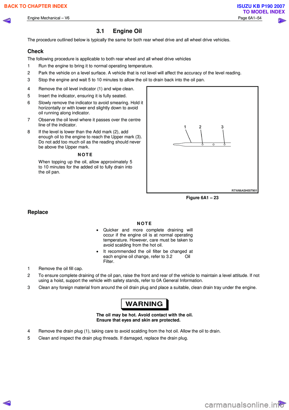
4 Remove the oil level indicator (1) and wipe clean.
5 Insert the indicator, ensuring it is fully seated.
6 Slowly remove the indicator to avoid smearing. Hold it horizontally or with lower end slightly down to avoid
oil running along indicator.
7 Observe the oil level where it passes over the centre line of the indicator.
8 If the level is lower than the Add mark (2), add enough oil to the engine to reach the Upper mark (3).
Do not add too much oil as the reading should never
be above the Upper mark.
NOTE
When topping up the oil, allow approximately 5
to 10 minutes for the added oil to fully drain into
the oil pan.
Figure 6A1 – 23
Replace
NOTE
• Quicker and more complete draining will
occur if the engine oil is at normal operating
temperature. However, care must be taken to
avoid scalding from the hot oil.
• It recommended the oil filter be changed at
each engine oil change, refer to 3.2 Oil
Filter.
1 Remove the oil fill cap.
2 To ensure complete draining of the oil pan, raise the front and rear of the vehicle to maintain a level attitude. If not using a hoist, support the vehicle with safety stands, refer to 0A General Information.
3 Clean any foreign material from around the oil drain plug and place a suitable, clean drain tray under the engine.
The oil may be hot. Avoid contact with the oil.
Ensure that eyes and skin are protected.
4 Remove the drain plug (1), taking care to avoid scalding from the hot oil. Allow the oil to drain.
5 Clean and inspect the drain plug threads. If damaged, replace the drain plug.
BACK TO CHAPTER INDEX
TO MODEL INDEX
ISUZU KB P190 2007
Page 2556 of 6020
Engine Mechanical – V6 Page 6A1–77
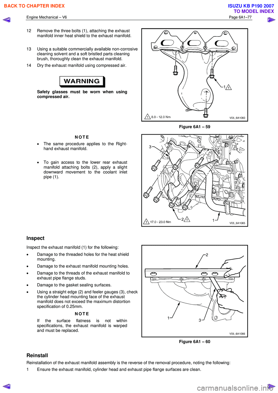
12 Remove the three bolts (1), attaching the exhaust
manifold inner heat shield to the exhaust manifold.
13 Using a suitable commercially available non-corrosive cleaning solvent and a soft bristled parts cleaning
brush, thoroughly clean the exhaust manifold.
14 Dry the exhaust manifold using compressed air.
Safety glasses must be worn when using
compressed air.
Figure 6A1 – 59
NOTE
• The same procedure applies to the Right-
hand exhaust manifold.
• To gain access to the lower rear exhaust
manifold attaching bolts (2), apply a slight
downward movement to the coolant inlet
pipe (1).
Inspect
Inspect the exhaust manifold (1) for the following:
• Damage to the threaded holes for the heat shield
mounting.
• Damage to the exhaust manifold mounting holes.
• Damage to the threads of the exhaust manifold to
exhaust pipe flange studs.
• Damage to the gasket sealing surfaces.
• Using a straight edge (2) and feeler gauges (3), check
the cylinder head mounting face of the exhaust
manifold does not exceed the maximum distortion
specification of 0.25mm.
NOTE
If the surface flatness is not within
specifications, the exhaust manifold is warped
and must be replaced.
Figure 6A1 – 60
Reinstall
Reinstallation of the exhaust manifold assembly is the reverse of the removal procedure, noting the following:
1 Ensure the exhaust manifold, cylinder head and exhaust pipe flange surfaces are clean.
BACK TO CHAPTER INDEX
TO MODEL INDEX
ISUZU KB P190 2007
Page 2650 of 6020
Engine Mechanical – V6 Page 6A1–171
Valve Seat Width Measurement Procedure
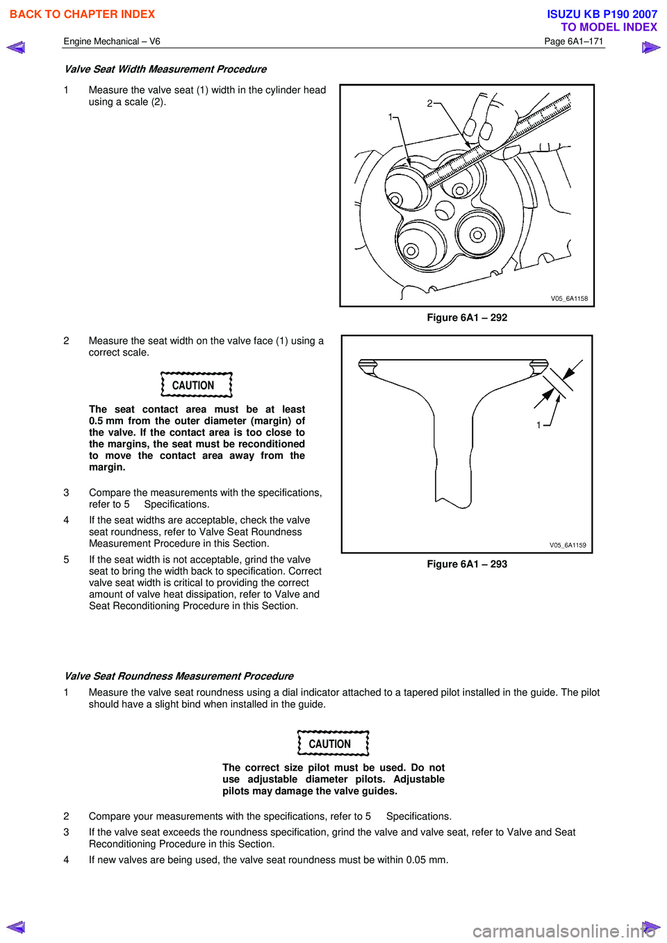
1 Measure the valve seat (1) width in the cylinder head
using a scale (2).
Figure 6A1 – 292
2 Measure the seat width on the valve face (1) using a correct scale.
CAUTION
The seat contact area must be at least
0.5 mm from the outer diameter (margin) of
the valve. If the contact area is too close to
the margins, the seat must be reconditioned
to move the contact area away from the
margin.
3 Compare the measurements with the specifications, refer to 5 Specifications.
4 If the seat widths are acceptable, check the valve seat roundness, refer to Valve Seat Roundness
Measurement Procedure in this Section.
5 If the seat width is not acceptable, grind the valve seat to bring the width back to specification. Correct
valve seat width is critical to providing the correct
amount of valve heat dissipation, refer to Valve and
Seat Reconditioning Procedure in this Section.
Figure 6A1 – 293
Valve Seat Roundness Measurement Procedure
1 Measure the valve seat roundness using a dial indicator attached to a tapered pilot installed in the guide. The pilot should have a slight bind when installed in the guide.
CAUTION
The correct size pilot must be used. Do not
use adjustable diameter pilots. Adjustable
pilots may damage the valve guides.
2 Compare your measurements with the specifications, refer to 5 Specifications.
3 If the valve seat exceeds the roundness specification, grind the valve and valve seat, refer to Valve and Seat Reconditioning Procedure in this Section.
4 If new valves are being used, the valve seat roundness must be within 0.05 mm.
BACK TO CHAPTER INDEX
TO MODEL INDEX
ISUZU KB P190 2007
Page 2651 of 6020
Engine Mechanical – V6 Page 6A1–172
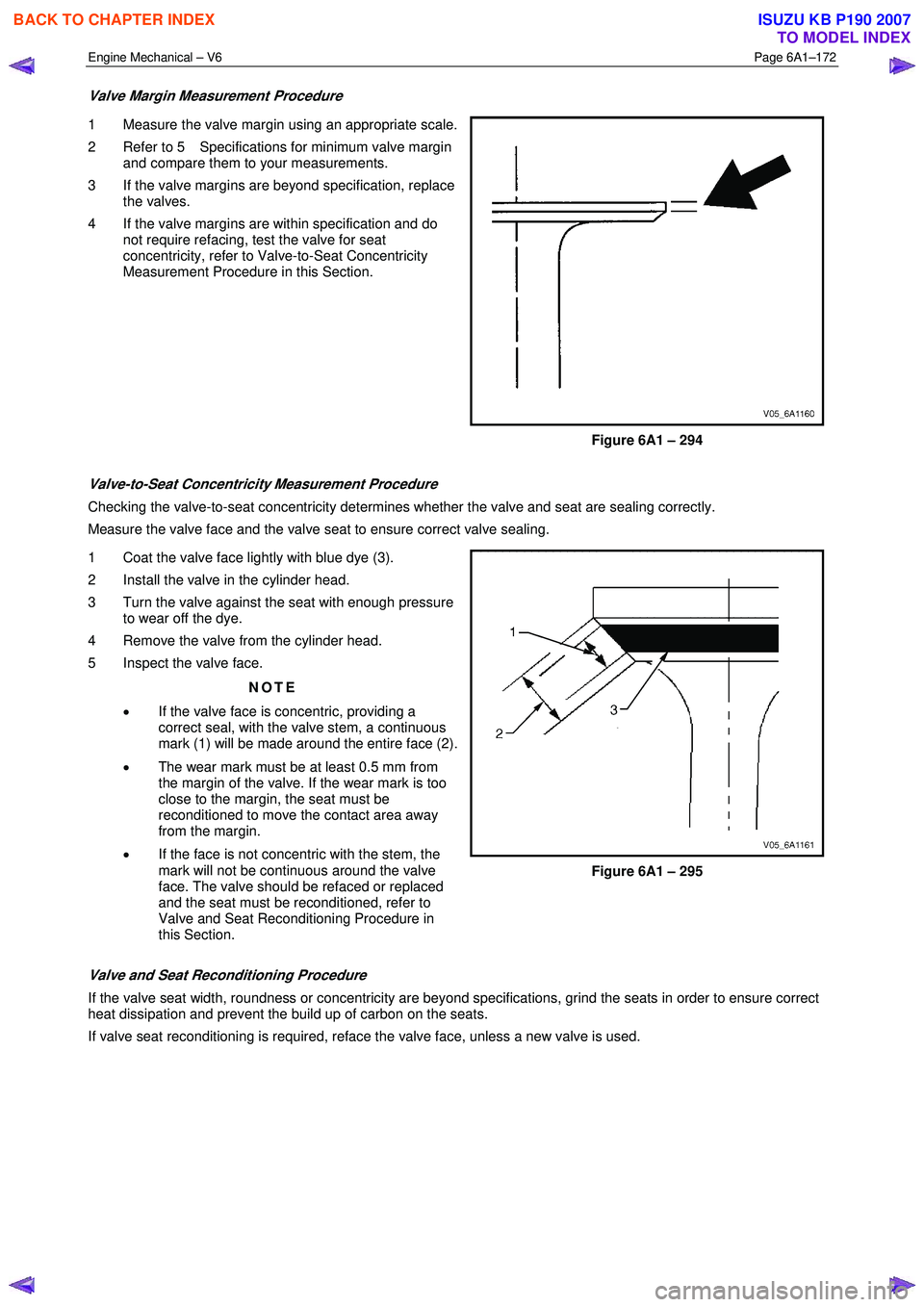
Valve Margin Measurement Procedure
1 Measure the valve margin using an appropriate scale.
2 Refer to 5 Specifications for minimum valve margin and compare them to your measurements.
3 If the valve margins are beyond specification, replace the valves.
4 If the valve margins are within specification and do not require refacing, test the valve for seat
concentricity, refer to Valve-to-Seat Concentricity
Measurement Procedure in this Section.
Figure 6A1 – 294
Valve-to-Seat Concentricity Measurement Procedure
Checking the valve-to-seat concentricity determines whether the valve and seat are sealing correctly.
Measure the valve face and the valve seat to ensure correct valve sealing.
1 Coat the valve face lightly with blue dye (3).
2 Install the valve in the cylinder head.
3 Turn the valve against the seat with enough pressure to wear off the dye.
4 Remove the valve from the cylinder head.
5 Inspect the valve face.
NOTE
• If the valve face is concentric, providing a
correct seal, with the valve stem, a continuous
mark (1) will be made around the entire face (2).
• The wear mark must be at least 0.5 mm from
the margin of the valve. If the wear mark is too
close to the margin, the seat must be
reconditioned to move the contact area away
from the margin.
• If the face is not concentric with the stem, the
mark will not be continuous around the valve
face. The valve should be refaced or replaced
and the seat must be reconditioned, refer to
Valve and Seat Reconditioning Procedure in
this Section.
Figure 6A1 – 295
Valve and Seat Reconditioning Procedure
If the valve seat width, roundness or concentricity are beyond specifications, grind the seats in order to ensure correct
heat dissipation and prevent the build up of carbon on the seats.
If valve seat reconditioning is required, reface the valve face, unless a new valve is used.
BACK TO CHAPTER INDEX
TO MODEL INDEX
ISUZU KB P190 2007