check engine light ISUZU KB P190 2007 Workshop Repair Manual
[x] Cancel search | Manufacturer: ISUZU, Model Year: 2007, Model line: KB P190, Model: ISUZU KB P190 2007Pages: 6020, PDF Size: 70.23 MB
Page 3277 of 6020
Engine Management – V6 – General Information Page 6C1-1–35
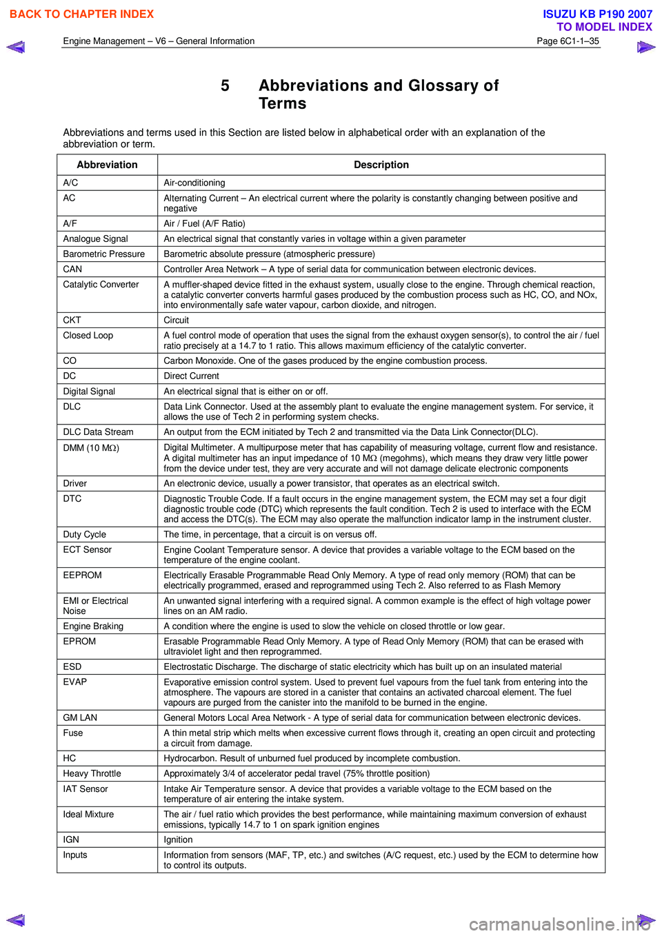
5 Abbreviations and Glossary of
Te r m s
Abbreviations and terms used in this Section are listed below in alphabetical order with an explanation of the
abbreviation or term.
Abbreviation Description
A/C Air-conditioning
AC Alternating Current – An electrical current where the polarity is constantly changing between positive and
negative
A/F Air / Fuel (A/F Ratio)
Analogue Signal An electrical signal that constantly varies in voltage within a given parameter
Barometric Pressure Barometric absolute pressure (atmospheric pressure)
CAN Controller Area Network – A type of serial data for communication between electronic devices.
Catalytic Converter
A muffler-shaped device fitted in the exhaust system, usually close to the engine. Through chemical reaction,
a catalytic converter converts harmful gases produced by the combustion process such as HC, CO, and NOx,
into environmentally safe water vapour, carbon dioxide, and nitrogen.
CKT Circuit
Closed Loop A fuel control mode of operation that uses the signal from the exhaust oxygen sensor(s), to control the air / fuel
ratio precisely at a 14.7 to 1 ratio. This allows maximum efficiency of the catalytic converter.
CO Carbon Monoxide. One of the gases produced by the engine combustion process.
DC Direct Current
Digital Signal An electrical signal that is either on or off.
DLC
Data Link Connector. Used at the assembly plant to evaluate the engine management system. For service, it
allows the use of Tech 2 in performing system checks.
DLC Data Stream An output from the ECM initiated by Tech 2 and transmitted via the Data Link Connector(DLC).
DMM (10 M Ω) Digital Multimeter. A multipurpose meter that has capability of measuring voltage, current flow and resistance.
A digital multimeter has an input impedance of 10 M Ω (megohms), which means they draw very little power
from the device under test, they are very accurate and will not damage delicate electronic components
Driver An electronic device, usually a power transistor, that operates as an electrical switch.
DTC
Diagnostic Trouble Code. If a fault occurs in the engine management system, the ECM may set a four digit
diagnostic trouble code (DTC) which represents the fault condition. Tech 2 is used to interface with the ECM
and access the DTC(s). The ECM may also operate the malfunction indicator lamp in the instrument cluster.
Duty Cycle The time, in percentage, that a circuit is on versus off.
ECT Sensor
Engine Coolant Temperature sensor. A device that provides a variable voltage to the ECM based on the
temperature of the engine coolant.
EEPROM Electrically Erasable Programmable Read Only Memory. A type of read only memory (ROM) that can be
electrically programmed, erased and reprogrammed using Tech 2. Also referred to as Flash Memory
EMI or Electrical
Noise An unwanted signal interfering with a required signal. A common example is the effect of high voltage power
lines on an AM radio.
Engine Braking A condition where the engine is used to slow the vehicle on closed throttle or low gear.
EPROM Erasable Programmable Read Only Memory. A type of Read Only Memory (ROM) that can be erased with
ultraviolet light and then reprogrammed.
ESD Electrostatic Discharge. The discharge of static electricity which has built up on an insulated material
EVAP
Evaporative emission control system. Used to prevent fuel vapours from the fuel tank from entering into the
atmosphere. The vapours are stored in a canister that contains an activated charcoal element. The fuel
vapours are purged from the canister into the manifold to be burned in the engine.
GM LAN General Motors Local Area Network - A type of serial data for communication between electronic devices.
Fuse
A thin metal strip which melts when excessive current flows through it, creating an open circuit and protecting
a circuit from damage.
HC Hydrocarbon. Result of unburned fuel produced by incomplete combustion.
Heavy Throttle Approximately 3/4 of accelerator pedal travel (75% throttle position)
IAT Sensor
Intake Air Temperature sensor. A device that provides a variable voltage to the ECM based on the
temperature of air entering the intake system.
Ideal Mixture The air / fuel ratio which provides the best performance, while maintaining maximum conversion of exhaust
emissions, typically 14.7 to 1 on spark ignition engines
IGN Ignition
Inputs Information from sensors (MAF, TP, etc.) and switches (A/C request, etc.) used by the ECM to determine how
to control its outputs.
BACK TO CHAPTER INDEX
TO MODEL INDEX
ISUZU KB P190 2007
Page 3297 of 6020
Engine Management – V6 – Diagnostics Page 6C1-2–19
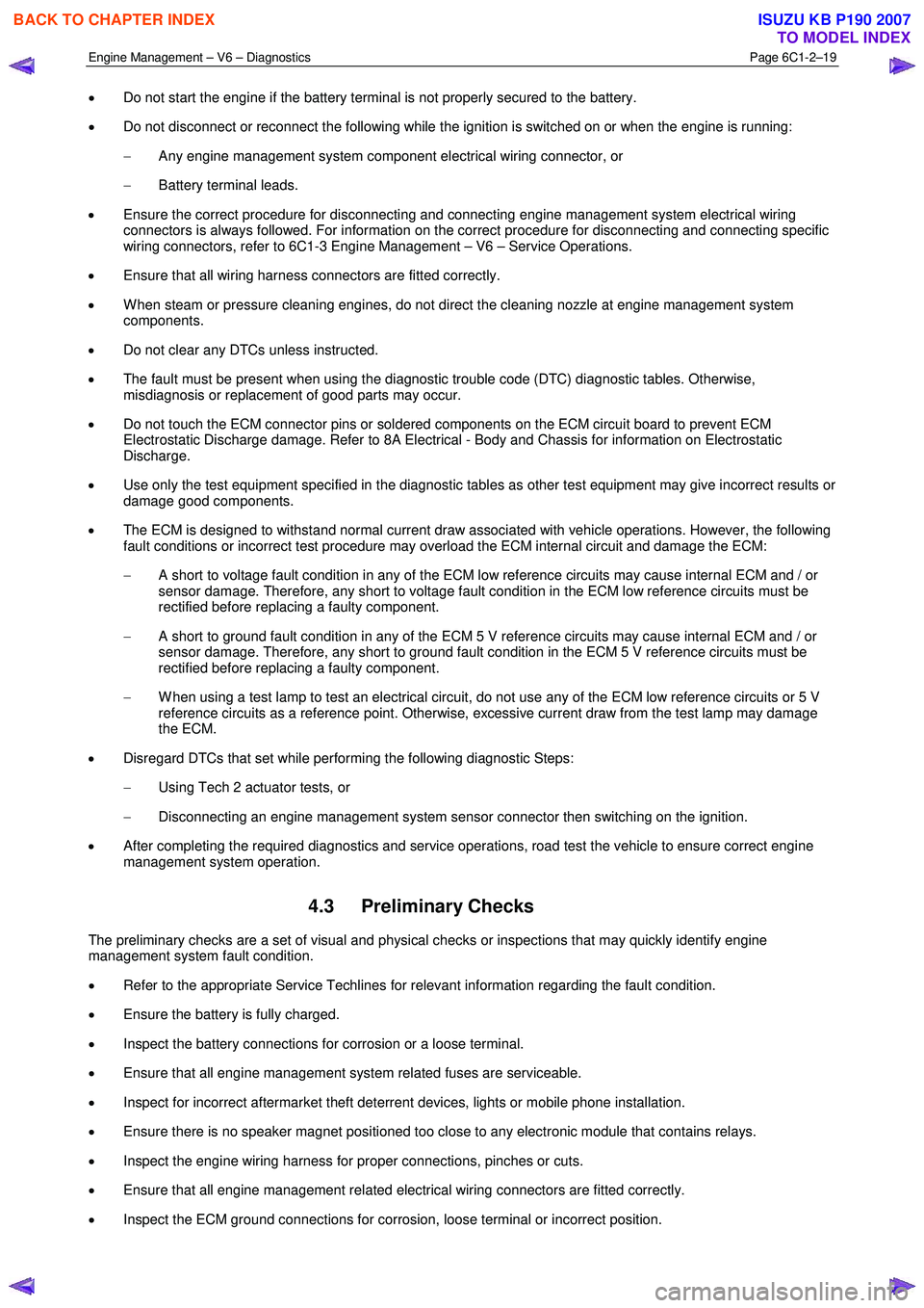
• Do not start the engine if the battery terminal is not properly secured to the battery.
• Do not disconnect or reconnect the following while the ignition is switched on or when the engine is running:
− Any engine management system component electrical wiring connector, or
− Battery terminal leads.
• Ensure the correct procedure for disconnecting and connecting engine management system electrical wiring
connectors is always followed. For information on the correct procedure for disconnecting and connecting specific
wiring connectors, refer to 6C1-3 Engine Management – V6 – Service Operations.
• Ensure that all wiring harness connectors are fitted correctly.
• W hen steam or pressure cleaning engines, do not direct the cleaning nozzle at engine management system
components.
• Do not clear any DTCs unless instructed.
• The fault must be present when using the diagnostic trouble code (DTC) diagnostic tables. Otherwise,
misdiagnosis or replacement of good parts may occur.
• Do not touch the ECM connector pins or soldered components on the ECM circuit board to prevent ECM
Electrostatic Discharge damage. Refer to 8A Electrical - Body and Chassis for information on Electrostatic
Discharge.
• Use only the test equipment specified in the diagnostic tables as other test equipment may give incorrect results or
damage good components.
• The ECM is designed to withstand normal current draw associated with vehicle operations. However, the following
fault conditions or incorrect test procedure may overload the ECM internal circuit and damage the ECM:
− A short to voltage fault condition in any of the ECM low reference circuits may cause internal ECM and / or
sensor damage. Therefore, any short to voltage fault condition in the ECM low reference circuits must be
rectified before replacing a faulty component.
− A short to ground fault condition in any of the ECM 5 V reference circuits may cause internal ECM and / or
sensor damage. Therefore, any short to ground fault condition in the ECM 5 V reference circuits must be
rectified before replacing a faulty component.
− W hen using a test lamp to test an electrical circuit, do not use any of the ECM low reference circuits or 5 V
reference circuits as a reference point. Otherwise, excessive current draw from the test lamp may damage
the ECM.
• Disregard DTCs that set while performing the following diagnostic Steps:
− Using Tech 2 actuator tests, or
− Disconnecting an engine management system sensor connector then switching on the ignition.
• After completing the required diagnostics and service operations, road test the vehicle to ensure correct engine
management system operation.
4.3 Preliminary Checks
The preliminary checks are a set of visual and physical checks or inspections that may quickly identify engine
management system fault condition.
• Refer to the appropriate Service Techlines for relevant information regarding the fault condition.
• Ensure the battery is fully charged.
• Inspect the battery connections for corrosion or a loose terminal.
• Ensure that all engine management system related fuses are serviceable.
• Inspect for incorrect aftermarket theft deterrent devices, lights or mobile phone installation.
• Ensure there is no speaker magnet positioned too close to any electronic module that contains relays.
• Inspect the engine wiring harness for proper connections, pinches or cuts.
• Ensure that all engine management related electrical wiring connectors are fitted correctly.
• Inspect the ECM ground connections for corrosion, loose terminal or incorrect position.
BACK TO CHAPTER INDEX
TO MODEL INDEX
ISUZU KB P190 2007
Page 3301 of 6020
Engine Management – V6 – Diagnostics Page 6C1-2–23
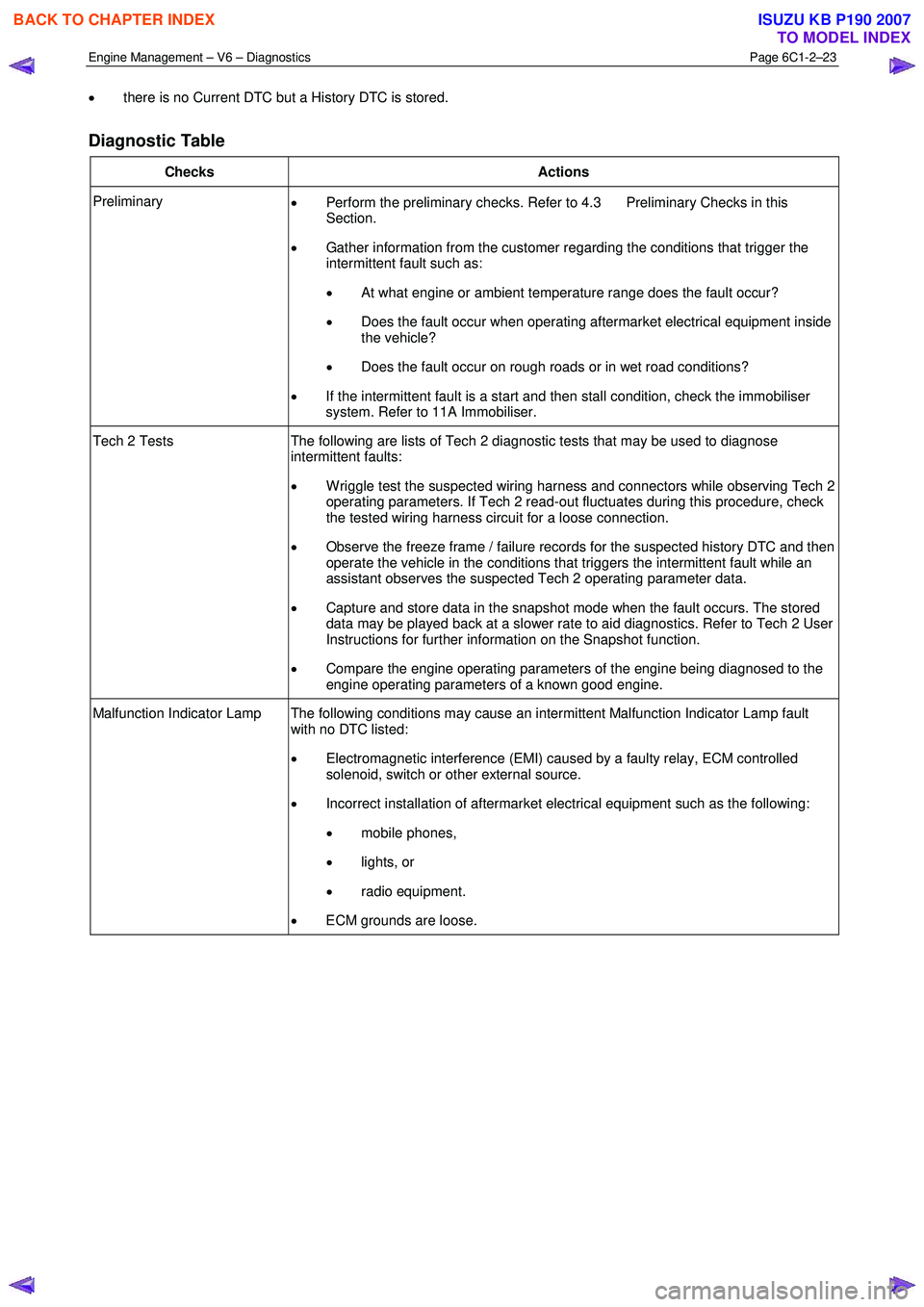
• there is no Current DTC but a History DTC is stored.
Diagnostic Table
Checks Actions
Preliminary
• Perform the preliminary checks. Refer to 4.3 Preliminary Checks in this
Section.
• Gather information from the customer regarding the conditions that trigger the
intermittent fault such as:
• At what engine or ambient temperature range does the fault occur?
• Does the fault occur when operating aftermarket electrical equipment inside
the vehicle?
• Does the fault occur on rough roads or in wet road conditions?
• If the intermittent fault is a start and then stall condition, check the immobiliser
system. Refer to 11A Immobiliser.
Tech 2 Tests The following are lists of Tech 2 diagnostic tests that may be used to diagnose
intermittent faults:
• W riggle test the suspected wiring harness and connectors while observing Tech 2
operating parameters. If Tech 2 read-out fluctuates during this procedure, check
the tested wiring harness circuit for a loose connection.
• Observe the freeze frame / failure records for the suspected history DTC and then
operate the vehicle in the conditions that triggers the intermittent fault while an
assistant observes the suspected Tech 2 operating parameter data.
• Capture and store data in the snapshot mode when the fault occurs. The stored
data may be played back at a slower rate to aid diagnostics. Refer to Tech 2 User
Instructions for further information on the Snapshot function.
• Compare the engine operating parameters of the engine being diagnosed to the
engine operating parameters of a known good engine.
Malfunction Indicator Lamp The following conditions may cause an intermittent Malfunction Indicator Lamp fault with no DTC listed:
• Electromagnetic interference (EMI) caused by a faulty relay, ECM controlled
solenoid, switch or other external source.
• Incorrect installation of aftermarket electrical equipment such as the following:
• mobile phones,
• lights, or
• radio equipment.
• ECM grounds are loose.
BACK TO CHAPTER INDEX
TO MODEL INDEX
ISUZU KB P190 2007
Page 3302 of 6020
Engine Management – V6 – Diagnostics Page 6C1-2–24
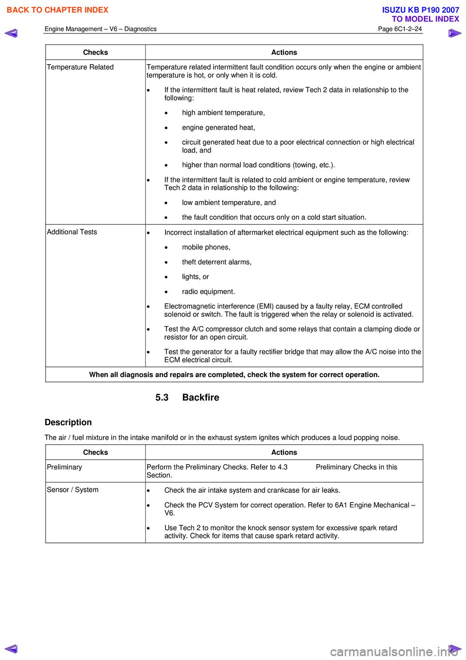
Checks Actions
Temperature Related Temperature related intermittent fault condition occurs only when the engine or ambient
temperature is hot, or only when it is cold.
• If the intermittent fault is heat related, review Tech 2 data in relationship to the
following:
• high ambient temperature,
• engine generated heat,
• circuit generated heat due to a poor electrical connection or high electrical
load, and
• higher than normal load conditions (towing, etc.).
• If the intermittent fault is related to cold ambient or engine temperature, review
Tech 2 data in relationship to the following:
• low ambient temperature, and
• the fault condition that occurs only on a cold start situation.
Additional Tests
• Incorrect installation of aftermarket electrical equipment such as the following:
• mobile phones,
• theft deterrent alarms,
• lights, or
• radio equipment.
• Electromagnetic interference (EMI) caused by a faulty relay, ECM controlled
solenoid or switch. The fault is triggered when the relay or solenoid is activated.
• Test the A/C compressor clutch and some relays that contain a clamping diode or
resistor for an open circuit.
• Test the generator for a faulty rectifier bridge that may allow the A/C noise into the
ECM electrical circuit.
When all diagnosis and repairs are completed, check the system for correct operation.
5.3 Backfire
Description
The air / fuel mixture in the intake manifold or in the exhaust system ignites which produces a loud popping noise.
Checks Actions
Preliminary Perform the Preliminary Checks. Refer to 4.3 Preliminary Checks in this
Section.
Sensor / System • Check the air intake system and crankcase for air leaks.
• Check the PCV System for correct operation. Refer to 6A1 Engine Mechanical –
V6.
• Use Tech 2 to monitor the knock sensor system for excessive spark retard
activity. Check for items that cause spark retard activity.
BACK TO CHAPTER INDEX
TO MODEL INDEX
ISUZU KB P190 2007
Page 3448 of 6020
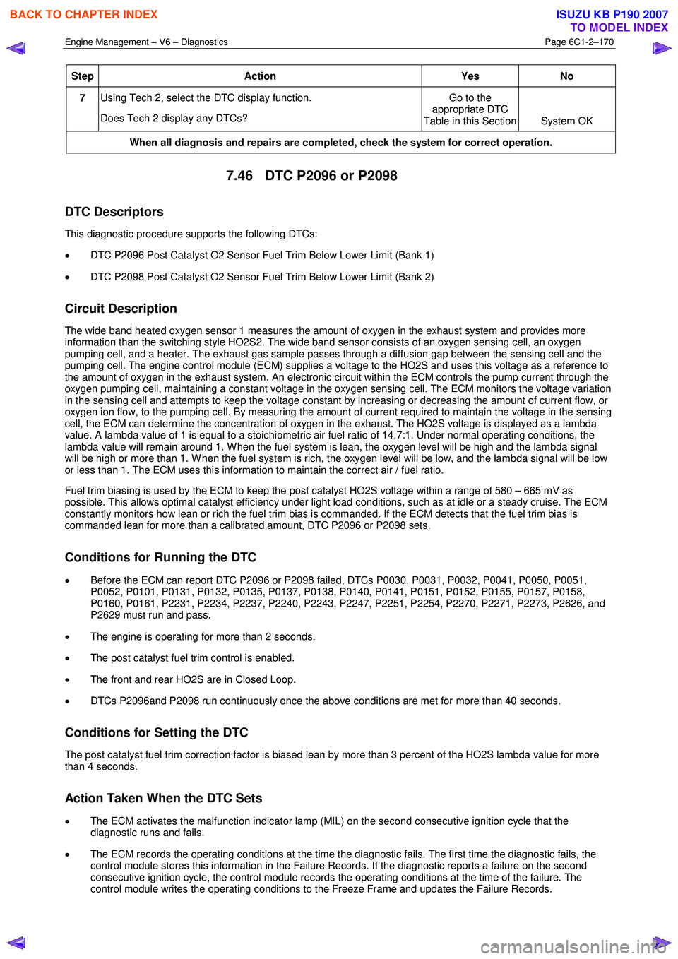
Engine Management – V6 – Diagnostics Page 6C1-2–170
Step Action Yes
No
7 Using Tech 2, select the DTC display function.
Does Tech 2 display any DTCs? Go to the
appropriate DTC
Table in this Section System OK
When all diagnosis and repairs are completed, check the system for correct operation.
7.46 DTC P2096 or P2098
DTC Descriptors
This diagnostic procedure supports the following DTCs:
• DTC P2096 Post Catalyst O2 Sensor Fuel Trim Below Lower Limit (Bank 1)
• DTC P2098 Post Catalyst O2 Sensor Fuel Trim Below Lower Limit (Bank 2)
Circuit Description
The wide band heated oxygen sensor 1 measures the amount of oxygen in the exhaust system and provides more
information than the switching style HO2S2. The wide band sensor consists of an oxygen sensing cell, an oxygen
pumping cell, and a heater. The exhaust gas sample passes through a diffusion gap between the sensing cell and the
pumping cell. The engine control module (ECM) supplies a voltage to the HO2S and uses this voltage as a reference to
the amount of oxygen in the exhaust system. An electronic circuit within the ECM controls the pump current through the
oxygen pumping cell, maintaining a constant voltage in the oxygen sensing cell. The ECM monitors the voltage variation
in the sensing cell and attempts to keep the voltage constant by increasing or decreasing the amount of current flow, or
oxygen ion flow, to the pumping cell. By measuring the amount of current required to maintain the voltage in the sensing
cell, the ECM can determine the concentration of oxygen in the exhaust. The HO2S voltage is displayed as a lambda
value. A lambda value of 1 is equal to a stoichiometric air fuel ratio of 14.7:1. Under normal operating conditions, the
lambda value will remain around 1. W hen the fuel system is lean, the oxygen level will be high and the lambda signal
will be high or more than 1. W hen the fuel system is rich, the oxygen level will be low, and the lambda signal will be low
or less than 1. The ECM uses this information to maintain the correct air / fuel ratio.
Fuel trim biasing is used by the ECM to keep the post catalyst HO2S voltage within a range of 580 – 665 mV as
possible. This allows optimal catalyst efficiency under light load conditions, such as at idle or a steady cruise. The ECM
constantly monitors how lean or rich the fuel trim bias is commanded. If the ECM detects that the fuel trim bias is
commanded lean for more than a calibrated amount, DTC P2096 or P2098 sets.
Conditions for Running the DTC
• Before the ECM can report DTC P2096 or P2098 failed, DTCs P0030, P0031, P0032, P0041, P0050, P0051,
P0052, P0101, P0131, P0132, P0135, P0137, P0138, P0140, P0141, P0151, P0152, P0155, P0157, P0158,
P0160, P0161, P2231, P2234, P2237, P2240, P2243, P2247, P2251, P2254, P2270, P2271, P2273, P2626, and
P2629 must run and pass.
• The engine is operating for more than 2 seconds.
• The post catalyst fuel trim control is enabled.
• The front and rear HO2S are in Closed Loop.
• DTCs P2096and P2098 run continuously once the above conditions are met for more than 40 seconds.
Conditions for Setting the DTC
The post catalyst fuel trim correction factor is biased lean by more than 3 percent of the HO2S lambda value for more
than 4 seconds.
Action Taken When the DTC Sets
• The ECM activates the malfunction indicator lamp (MIL) on the second consecutive ignition cycle that the
diagnostic runs and fails.
• The ECM records the operating conditions at the time the diagnostic fails. The first time the diagnostic fails, the
control module stores this information in the Failure Records. If the diagnostic reports a failure on the second
consecutive ignition cycle, the control module records the operating conditions at the time of the failure. The
control module writes the operating conditions to the Freeze Frame and updates the Failure Records.
BACK TO CHAPTER INDEX
TO MODEL INDEX
ISUZU KB P190 2007
Page 3586 of 6020
Engine Management – V6 – Service Operations Page 6C1-3–62
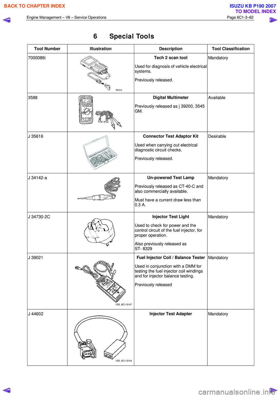
6 Special Tools
Tool Number Illustration Description Tool Classification
7000086i
Tech 2 scan tool
Used for diagnosis of vehicle electrical
systems.
Previously released. Mandatory
3588
Digital Multimeter
Previously released as j 39200, 3545
GM. Available
J 35616
Connector Test Adaptor Kit
Used when carrying out electrical
diagnostic circuit checks.
Previously released. Desirable
J 34142-a
Un-powered Test Lamp
Previously released as CT-40-C and
also commercially available.
Must have a current draw less than
0.3 A. Mandatory
J 34730-2C
Injector Test Light
Used to check for power and the
control circuit of the fuel injector, for
proper operation.
Also previously released as
ST- 8329 Mandatory
J 39021 Fuel Injector Coil / Balance Tester
Used in conjunction with a DMM for
testing the fuel injector coil windings
and for injector balance testing.
Previously released Mandatory
J 44602 Injector Test Adapter
Mandatory
BACK TO CHAPTER INDEX
TO MODEL INDEX
ISUZU KB P190 2007
Page 3597 of 6020
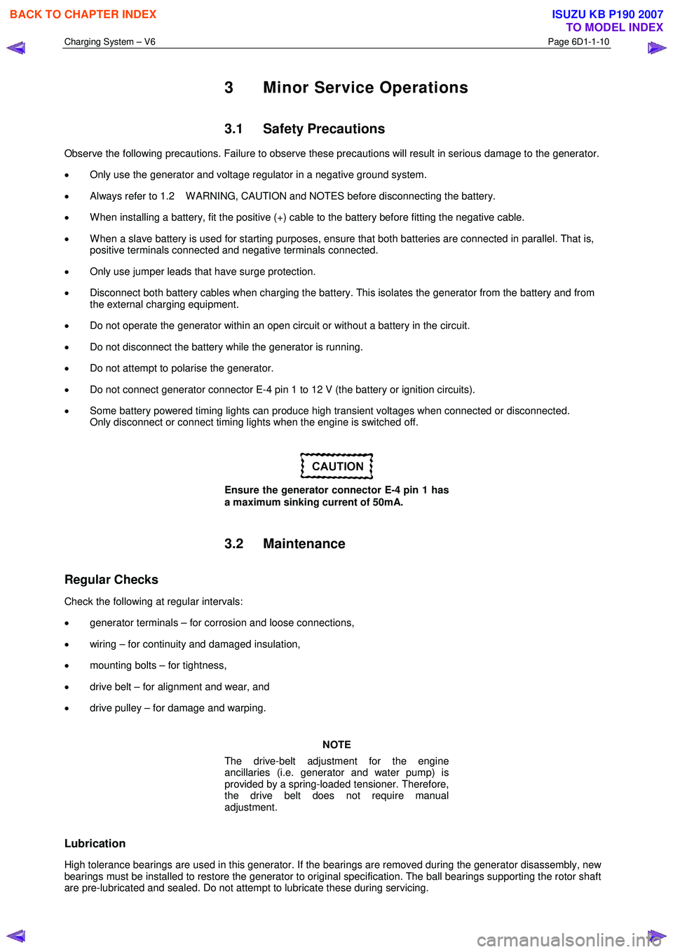
Charging System – V6 Page 6D1-1-10
3 Minor Service Operations
3.1 Safety Precautions
Observe the following precautions. Failure to observe these precautions will result in serious damage to the generator.
• Only use the generator and voltage regulator in a negative ground system.
• Always refer to 1.2 W ARNING, CAUTION and NOTES before disconnecting the battery.
• W hen installing a battery, fit the positive (+) cable to the battery before fitting the negative cable.
• W hen a slave battery is used for starting purposes, ensure that both batteries are connected in parallel. That is,
positive terminals connected and negative terminals connected.
• Only use jumper leads that have surge protection.
• Disconnect both battery cables when charging the battery. This isolates the generator from the battery and from
the external charging equipment.
• Do not operate the generator within an open circuit or without a battery in the circuit.
• Do not disconnect the battery while the generator is running.
• Do not attempt to polarise the generator.
• Do not connect generator connector E-4 pin 1 to 12 V (the battery or ignition circuits).
• Some battery powered timing lights can produce high transient voltages when connected or disconnected.
Only disconnect or connect timing lights when the engine is switched off.
Ensure the generator connector E-4 pin 1 has
a maximum sinking current of 50mA.
3.2 Maintenance
Regular Checks
Check the following at regular intervals:
• generator terminals – for corrosion and loose connections,
• wiring – for continuity and damaged insulation,
• mounting bolts – for tightness,
• drive belt – for alignment and wear, and
• drive pulley – for damage and warping.
NOTE
The drive-belt adjustment for the engine
ancillaries (i.e. generator and water pump) is
provided by a spring-loaded tensioner. Therefore,
the drive belt does not require manual
adjustment.
Lubrication
High tolerance bearings are used in this generator. If the bearings are removed during the generator disassembly, new
bearings must be installed to restore the generator to original specification. The ball bearings supporting the rotor shaft
are pre-lubricated and sealed. Do not attempt to lubricate these during servicing.
BACK TO CHAPTER INDEX
TO MODEL INDEX
ISUZU KB P190 2007
Page 3651 of 6020
Battery Page 6D1-3–11
b W ait 15 seconds for the battery to recover.
8 If possible, set the selector to 50% of rapid discharge current (or three times the 20 hour discharge rate).
9 Apply the load test for 10 seconds and record the battery voltage. If one cell is faulty it will gas excessively or overheat. This indicates a faulty battery.
10 Recharge the battery if the voltage is at or below the minimum voltage specified by the HRD manufacturer (or 9.6 V).
11 Replace the battery if the voltage is below the minimum voltage specified by the HRD manufacturer (or below 9.6 V after the battery is charged and the test is repeated). Refer to 4.1 Battery.
12 Connect the battery positive terminal.
13 Connect the battery negative terminal.
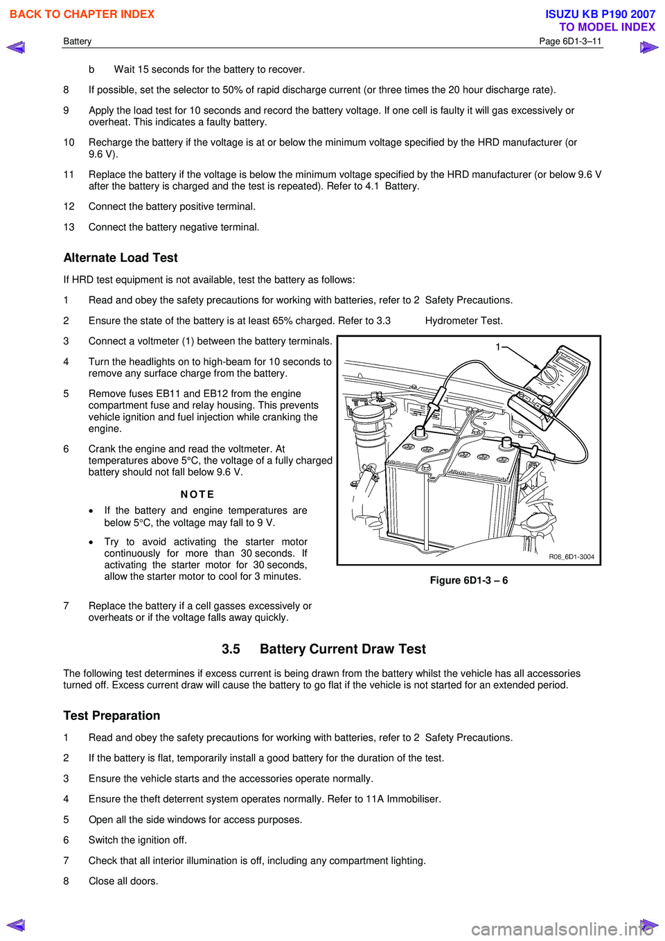
Alternate Load Test
If HRD test equipment is not available, test the battery as follows:
1 Read and obey the safety precautions for working with batteries, refer to 2 Safety Precautions.
2 Ensure the state of the battery is at least 65% charged. Refer to 3.3 Hydrometer Test.
3 Connect a voltmeter (1) between the battery terminals.
4 Turn the headlights on to high-beam for 10 seconds to remove any surface charge from the battery.
5 Remove fuses EB11 and EB12 from the engine compartment fuse and relay housing. This prevents
vehicle ignition and fuel injection while cranking the
engine.
6 Crank the engine and read the voltmeter. At temperatures above 5°C, the voltage of a fully charged
battery should not fall below 9.6 V.
NOTE
• If the battery and engine temperatures are
below 5 °C, the voltage may fall to 9 V.
• Try to avoid activating the starter motor
continuously for more than 30 seconds. If
activating the starter motor for 30 seconds,
allow the starter motor to cool for 3 minutes.
7 Replace the battery if a cell gasses excessively or overheats or if the voltage falls away quickly.
Figure 6D1-3 – 6
3.5 Battery Current Draw Test
The following test determines if excess current is being drawn from the battery whilst the vehicle has all accessories
turned off. Excess current draw will cause the battery to go flat if the vehicle is not started for an extended period.
Test Preparation
1 Read and obey the safety precautions for working with batteries, refer to 2 Safety Precautions.
2 If the battery is flat, temporarily install a good battery for the duration of the test.
3 Ensure the vehicle starts and the accessories operate normally.
4 Ensure the theft deterrent system operates normally. Refer to 11A Immobiliser.
5 Open all the side windows for access purposes.
6 Switch the ignition off.
7 Check that all interior illumination is off, including any compartment lighting.
8 Close all doors.
BACK TO CHAPTER INDEX
TO MODEL INDEX
ISUZU KB P190 2007
Page 3657 of 6020
Battery Page 6D1-3–17
4 Turn off the ignition, lights and all other electrical loads.
5 Check the battery filler caps on both batteries are tight.
6 Place a wet cloth over the battery filler caps of each battery.
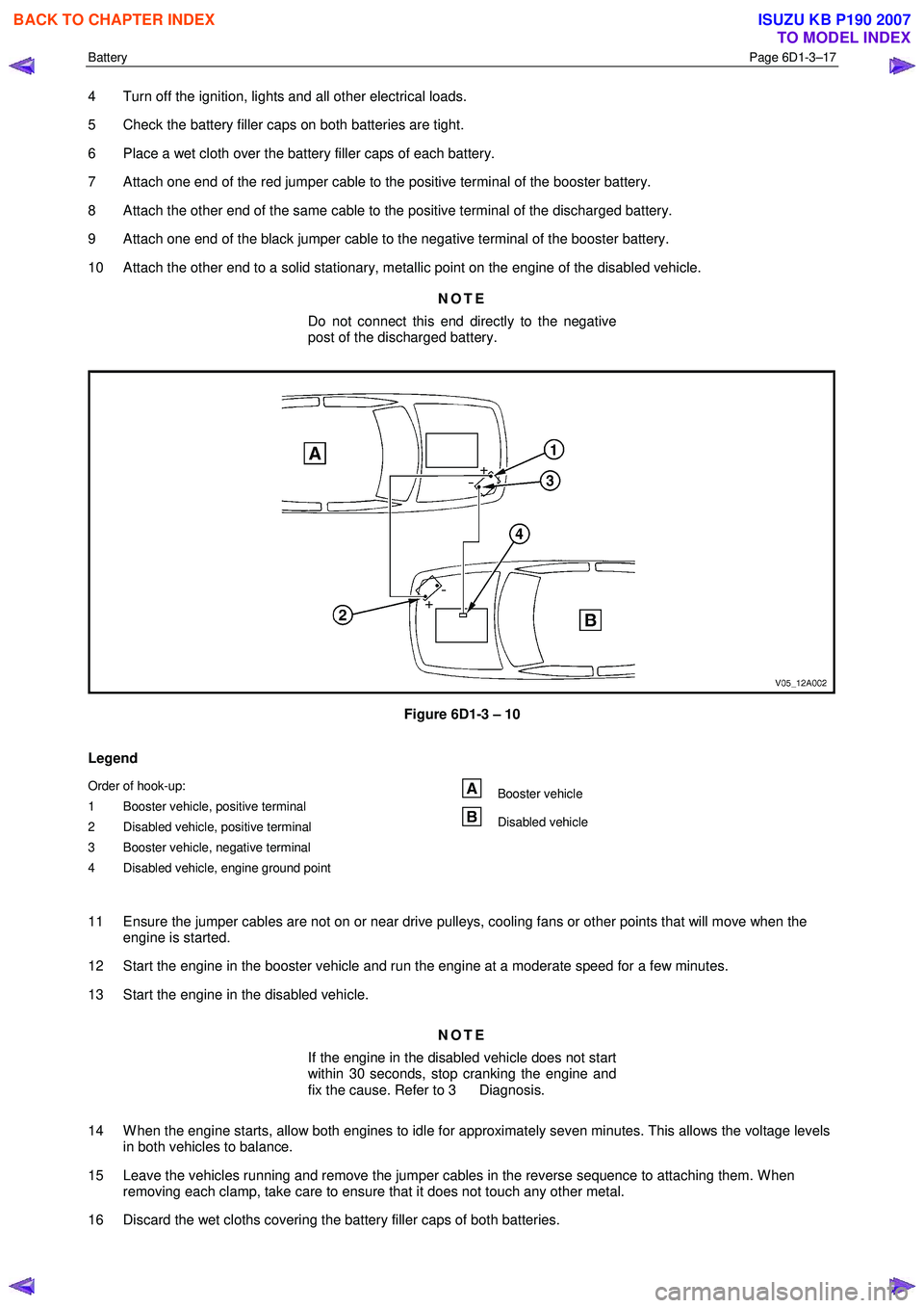
7 Attach one end of the red jumper cable to the positive terminal of the booster battery.
8 Attach the other end of the same cable to the positive terminal of the discharged battery.
9 Attach one end of the black jumper cable to the negative terminal of the booster battery.
10 Attach the other end to a solid stationary, metallic point on the engine of the disabled vehicle.
NOTE
Do not connect this end directly to the negative
post of the discharged battery.
Figure 6D1-3 – 10
Legend
Order of hook-up:
1 Booster vehicle, positive terminal
2 Disabled vehicle, positive terminal
3 Booster vehicle, negative terminal
4 Disabled vehicle, engine ground point Booster vehicle
Disabled vehicle
11 Ensure the jumper cables are not on or near drive pulleys, cooling fans or other points that will move when the engine is started.
12 Start the engine in the booster vehicle and run the engine at a moderate speed for a few minutes.
13 Start the engine in the disabled vehicle.
NOTE
If the engine in the disabled vehicle does not start
within 30 seconds, stop cranking the engine and
fix the cause. Refer to 3 Diagnosis.
14 W hen the engine starts, allow both engines to idle for approximately seven minutes. This allows the voltage levels in both vehicles to balance.
15 Leave the vehicles running and remove the jumper cables in the reverse sequence to attaching them. W hen removing each clamp, take care to ensure that it does not touch any other metal.
16 Discard the wet cloths covering the battery filler caps of both batteries.
BACK TO CHAPTER INDEX
TO MODEL INDEX
ISUZU KB P190 2007
Page 3690 of 6020
Powertrain Interface Module – V6 Page 6E1–29
Intermittent Fault Conditions
8.1 Intermittent Conditions Diagnostic Table
Description
A fault condition is intermittent if one of the following conditions exists:
• The fault condition is not always present.
• The fault condition cannot be presently duplicated.
• There is no Current DTC but a History DTC is stored.
Diagnostic Table
Checks Actions
Preliminary
• Perform the Preliminary Checks, refer to 7.1 Diagnostic Requirements,
Precautions and Preliminary Checks.
• Gather information from the customer regarding the conditions that trigger the
intermittent fault such as:
• At what engine or ambient temperature range does the fault occur?
• Does the fault occur when operating aftermarket electrical equipment inside
the vehicle?
• Does the fault occur on rough roads or in wet road conditions?
• If the intermittent fault is a start and then stall condition, check immobiliser system.
Refer to 11A Immobiliser.
Harness / Connector Install Tech 2 and perform the Tech 2 Intermittent Fault Tests. Refer to 4.1 Diagnostic General Descriptions for information on Tech 2 ECU diagnostic
tests.
W arning Indicator The following conditions may cause an intermittent Malfunction Indicator Lamp fault with
no DTC listed:
• Electromagnetic Interference (EMI) caused by a faulty relay, ECM controlled
solenoid, switch or other external source.
• Incorrect installation of aftermarket electrical equipment such as the following:
• mobile phones,
• theft deterrent alarms,
• lights, or
• radio equipment.
• Loose PIM ground connections.
BACK TO CHAPTER INDEX
TO MODEL INDEX
ISUZU KB P190 2007