Circuit ISUZU KB P190 2007 Workshop Repair Manual
[x] Cancel search | Manufacturer: ISUZU, Model Year: 2007, Model line: KB P190, Model: ISUZU KB P190 2007Pages: 6020, PDF Size: 70.23 MB
Page 4463 of 6020

ON-VEHICLE SERVICE (JR405E) 7A3-9
TURBINE SENSOR
The turbine sensor is attached to the right side of the
transmission.
Inspect
1. During driving at a speed of 20km/h (12mph) with “L” range in low gear, measure the voltage between the
TCM connector terminals (B3) and (B5) with a digital
voltmeter.
Standard voltage : approx. 7V (AC range)
2. If the voltage is outside of the standard value, check the turbine sensor pole piece for presence of foreign
materials and the turbine sensor cable for a short o
r
open circuit.
If the result of the inspection is abnormal, replace the turbine sensor.
Torque: 6 N·m (0.6 kgf·m/52 lb·in)
POWER AND 3RD START SWITCH
Inspect
1. Block the wheels.
2. Disconnect the negative battery cable.
3. Pry out the switch from the floor console.
4. Disconnect the harness connector.
5. Check continuity between terminals (5) and (6) at third (3rd) position.
6. Check continuity between terminals (3) and (6) at power (PW R) position.
7. Replace the power and 3rd start switch if the result o
f
inspection is abnormal.
8. Connect the harness connector.
9. Connect the negative battery cable.
10. Remove the wheel blocks.
238R300003
BACK TO CHAPTER INDEX
TO MODEL INDEX
ISUZU KB P190 2007
Page 4473 of 6020

ON-VEHICLE SERVICE (JR405E) 7A3-19
Install or Connect
1. Align the manual valve and the manual plate of the
transmission case.
43ASSY119
2. Install the control valve assembly and tighten the 12 fixing bolts to the specified torque.
Number of bolts Length Color
10 (A) 40 mm (1.57 in) Gold
2 (B) 30 mm (1.18 in) Gold
Bolt torque : 8 N·m (0.8 kgf·m/69 lb·in)
3. Connect the 2 harness connectors.
4. If removed, install the oil strainer.
Refer to “Solenoids, Oil Pressure Switch and Oil Temperature Sensor” previously in this section.
5. Install the new gasket and oil pan.
Bolt torque : 8 N·m (0.8 kgf·m/69 lb·in)
6. Fill with the fluid.
Refer to “ATF CHANGE” in this section.
7. Connect the negative battery cable.
8. Remove the wheel blocks.
FLUSHING THE TRANSMISSION FLUID COOLER AND LINE
The fluid cooler and lines may be flushed under the
following condition. This will help prevent more trouble
after the transmission is repaired.
1. W hen an abnormal amount of debris is found.
2. W hen an abnormal wear or chips on gears and shafts is found while overhauling.
3. W hen there is abnormal clutch facing wear and oil contamination found.
Procedures
1. Block the wheels.
2. Disconnect the negative battery cable.
3. Raise the vehicle and support it with suitable safet
y
stands.
4. Disconnect the fluid cooler lines at the transmission case and fluid cooler.
5. Flush and back-flush the fluid cooler and lines using solvent and compressed air.
Note:
DO NOT exceed (200 kPa/2.0 kgf/cm
2/28 psi) air
pressure, or damage may result to oil cooler.
6. Remove all remaining solvent from the system with
compressed air.
7. Flush the cooling system again with Automatic Transmission Fluid (ATF).
After the final flush, connect all lines.
Cooler line joint connector torque :
44 N·m (4.5 kgf·m/33 lb·ft)
8. Replenish the ATF.
9. Start the engine to test the system for the free flow o
f
fluid. If the flow is restricted, the cooler assembly o
r
lines must be replaced.
Repeated cleaning and flushing may not remove all the debris from the fluid cooler circuit.
Move the select lever through the various ranges and return to neutral.
Check for fluid level.
If the fluid level is below the specified range, ATF must be added.
10. Connect the negative battery cable.
11. Remove the safety stands.
12. Remove the wheel blocks.
BACK TO CHAPTER INDEX
TO MODEL INDEX
ISUZU KB P190 2007
Page 4823 of 6020

CLUTCH 7C-45
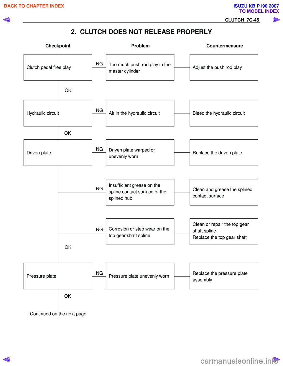
2. CLUTCH DOES NOT RELEASE PROPERLY
Checkpoint Problem Countermeasure
Adjust the push rod play
Too much push rod play in the
master cylinder
NG
Clutch pedal free play
Driven plate
Replace the driven plate
Driven plate warped or
unevenly worn
Hydraulic circuit
Bleed the hydraulic circuit
Air in the hydraulic circuit
OK
NG
NG
OK
Clean or repair the top gear
shaft spline
Replace the top gear shaft
Corrosion or step wear on the
top gear shaft spline
Pressure plate
Replace the pressure plate
assembly
Clean and grease the splined
contact surface
Pressure plate unevenly worn
Insufficient grease on the
spline contact surface of the
splined hub
OK NG
NG
NG
OK
Continued on the next page
BACK TO CHAPTER INDEX
TO MODEL INDEX
ISUZU KB P190 2007
Page 4875 of 6020

TRANSFER CONTROL SYSTEM 7D1-1
SECTION 7D1
TRANSFER CONTROL SYSTEM
TABLE OF CONTENTS
PAGE
Service Precaution ..................................................................................................... 7D1 - 2
General Description ................................................................................................... 7D1 - 3
System Components .................................................................................................. 7D1 - 5 Parts Location ....................................................................................................... 7D1 - 5
Functions of Switch and Indicator Lamp ................................................................. 7D1 - 12
Parts Location ............................................................................................................ 7D1 - 24
Circuit Diagram ........................................................................................................... 7D1 - 33
Connector List ............................................................................................................ 7D1 - 41
Diagnosis .................................................................................................................... 7D1 - 46
Before determining a trouble (Non-trouble mode) ............................................ 7D1 - 46
Memory erasing procedure ....................................................................................... 7D1 - 52
Diagnosis from symptom ........................................................................................... 7D1 - 54
BACK TO CHAPTER INDEX
TO MODEL INDEX
ISUZU KB P190 2007
Page 4881 of 6020

TRANSFER CONTROL SYSTEM 7D1-7
7B4-PDF3
4L indicator (in meter panel)
This lamp indicates following items:
Valve check
Driving status (High-Low)
Operating status (2Hz: Actuator in operation, mechanism
standby)
Restrictions on operation (4Hz)
RTW 77DSH000601
Neutral indicator (in operation switch panel)
This LED indicates following items:
LED check
Driving status (Neutral)
Operating status (2Hz: Actuator in operation, mechanism
standby)
Restrictions on operation (4Hz)
7B4-PDF5
Check 4WD warning light (in meter panel)
This light indicates following items:
Valve check
Faulty actuator limit SW , and circuit related faults with the limit
switch
RTW 77DSH000501
4WD switch
Switch to transmit a switching command to the 2H, 4H,
Neutral, or 4L position.
It comprises 3 PUSH momentary switches. By pushing the 2H
and 4L switches for 10 seconds,
operation is changed to the neutral position.
To shift from the neutral to another position, push another
switch for 10 seconds.
BACK TO CHAPTER INDEX
TO MODEL INDEX
ISUZU KB P190 2007
Page 4907 of 6020

TRANSFER CONTROL SYSTEM 7D1-33
CIRCUIT DIAGRAM
C24SE
RTW 680XF014201
BACK TO CHAPTER INDEX
TO MODEL INDEX
ISUZU KB P190 2007
Page 4925 of 6020

TRANSFER CONTROL SYSTEM 7D1-51
Trouble diagnosis based on the operation switch, transfer indicator lamp and operating
sound “Check 4WD” indicator ON (operation guard based on the transfer actuator
position detection error)
This condition indicates a faulty circuit related with the detection (limit) switches of the system actuator.
Detection (limit) switches detect the actuator operating angle based on their combinations.
The controller monitors transition of the actuator based on the combination of the detection (limit) switch output.
If the transition based on the combinations indicates some trouble, it is memorized, and shifting operation is
stopped when the trouble is counted 5 times, and the “Check 4W D” indicator lights up. At this time, the system
permits operation to 2H only.
W hen such a condition occurs, inspection of the transfer shift actuator, checking of the harness related with the
detection (limit) switch, and erasure of the memory of the controller is required.
(Refer to the memory erasure procedure for the erasure of the memory.)
At this time, the position indicator may flash at 4Hz. It means that a detection (limit) switch trouble wad detected
in the operation process shown by that position indicator (example: 4W D indicator when shifting from 2H to 4H).
Caution:
During trouble diagnosis and correction, do not turn ON the ignition with the harness connector of the
transfer actuator disconnected. (Do not disconnect the harness connector of the transfer actuator when
the ignition is ON.)
If the controller is connected during this condition, a limit SW trouble is judged and the above-described
“Check 4WD” condition occurs.
This can be reset by clearing the memory.
When disconnecting the harness connector of the actuator and turning the ignition ON is required, remove
the controller at the same time or remove the IG power fuse of the transfer controller.
BACK TO CHAPTER INDEX
TO MODEL INDEX
ISUZU KB P190 2007
Page 4926 of 6020

7D1-52 TRANSFER CONTROL SYSTEM
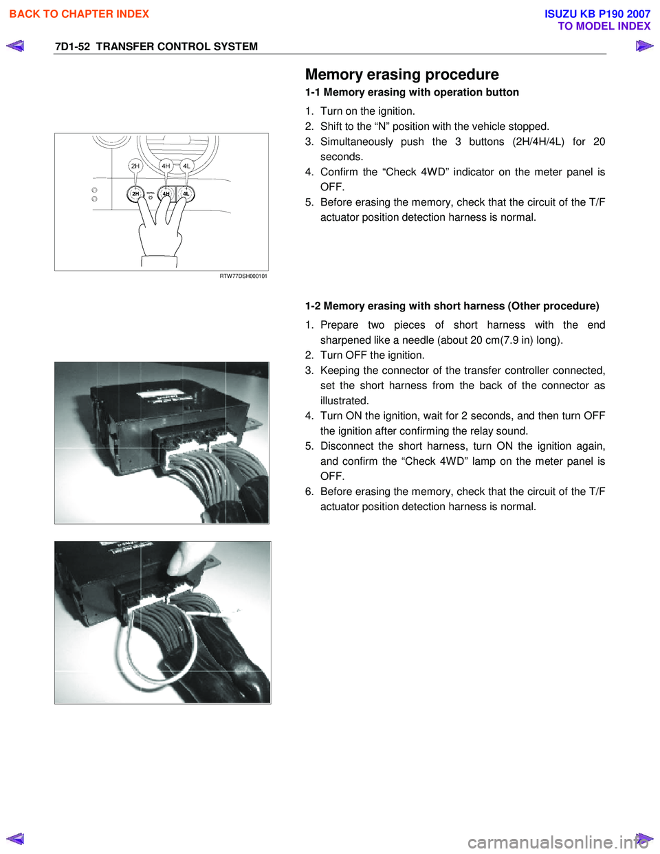
Memory erasing procedure
1-1 Memory erasing with operation button
1. Turn on the ignition.
2. Shift to the “N” position with the vehicle stopped.
RTW 77DSH000101
3. Simultaneously push the 3 buttons (2H/4H/4L) for 20
seconds.
4. Confirm the “Check 4W D” indicator on the meter panel is OFF.
5. Before erasing the memory, check that the circuit of the T/F actuator position detection harness is normal.
1-2 Memory erasing with short harness (Other procedure)
1. Prepare two pieces of short harness with the end sharpened like a needle (about 20 cm(7.9 in) long).
2. Turn OFF the ignition.
3. Keeping the connector of the transfer controller connected,
set the short harness from the back of the connector as
illustrated.
4. Turn ON the ignition, wait for 2 seconds, and then turn OFF the ignition after confirming the relay sound.
5. Disconnect the short harness, turn ON the ignition again, and confirm the “Check 4W D” lamp on the meter panel is
OFF.
6. Before erasing the memory, check that the circuit of the T/F actuator position detection harness is normal.
BACK TO CHAPTER INDEX
TO MODEL INDEX
ISUZU KB P190 2007
Page 4929 of 6020

TRANSFER CONTROL SYSTEM 7D1-55
Cannot shift from 2WD to 4H or 4L.
When shifting from 2H to other position, the indicator (4WD, 4Lo, Check4WD, neutral)
does not respond.
Step Action Yes No
1 Is the ignition switch ON? Go to step 2.
Turn the ignition switch ON and
trace this chart from the
beginning.
2 Does the transfer-related
indicators (4W D, 4Lo, Check
4W D, neutral) light up for 2
seconds when the ignition switch
is turned ON? Failed operation switch. Or,
Failed controller. Indicator lamp burnt out.
Disconnected harness wire.
After repairing, trace this chart
from the beginning.
Even after correction step 1-1(*), 4WD indicator blinks at 4Hz and changes to 2H after 10
seconds.
Step Action Yes No
1 Is the ignition switch ON? Go to step 2.
Turn the ignition switch ON and
trace this chart from the
beginning.
2 Does the transfer-related
indicators (4W D, 4Lo, Check
4W D, neutral) light up for 2
seconds when the ignition switch
is turned ON? Go to step 3.
Indicator lamp burnt out.
Disconnected harness wire.
After repairing, trace this chart
from the beginning.
3 After 2 seconds, check that the
Check4W D lamp is ON or OFF.
Is the Check4W D lamp OFF? Go to step 4.
Failed actuator position detection
switch (LS1, LS2, LS3, LS4,
GND).
Short or disconnection of harness
of this detection switch.
After repairing, trace this chart
from the beginning.
4 Press the 4H button.
Is sound of relay heard from the
transfer control? Go to step 5.
Failed controller.
Replace the controller and trace
this chart from the beginning.
5 Is the sound of a running motor
heard? Failed control system of the
transfer mechanism. Check and
repair and trace this chart from
the beginning. Failed actuator motor.
Disconnected controller motor
drive output circuit, GND short
circuit. +B fuse blown out.
Disconnection of that harness.
After repairing, trace this chart
from the beginning.
*Before determining a trouble (Non-trouble mode)
BACK TO CHAPTER INDEX
TO MODEL INDEX
ISUZU KB P190 2007
Page 4931 of 6020

TRANSFER CONTROL SYSTEM 7D1-57
After operation, indicator of target position blinks for 1.5 sec. at 2Hz, return to 2H
condition (4WD indicator going out)
Step Action Yes No
1 Keep pressing the 4H button
(about 10 seconds).
Does the 4W D indicator blink at
2Hz for 15 seconds and then
blink at 4Hz? Failed actuator motor.
Disconnection of controller motor
drive output circuit, or GND short.
+B fuse blown out.
Disconnection of that harness.
After repairing, trace this chart
from the beginning. Go to step 2.
2
Press the 4H button.
Is the sound of relay heard from
the transfer controller? Go to step 3.
Failed controller.
Replace the controller and trace
this chart from the beginning.
3 Is the sound of running motor
heard? Failed control system of the
transfer mechanism. Check and
repair and trace this chart from
the beginning. Failed actuator motor.
Disconnection or GND short of
controller motor drive output
circuit.
After repairing, trace this chart
from the beginning.
BACK TO CHAPTER INDEX
TO MODEL INDEX
ISUZU KB P190 2007