Circuit ISUZU KB P190 2007 Workshop Repair Manual
[x] Cancel search | Manufacturer: ISUZU, Model Year: 2007, Model line: KB P190, Model: ISUZU KB P190 2007Pages: 6020, PDF Size: 70.23 MB
Page 4424 of 6020
7A2-140 TRANSMISSION CONTROL SYSTEM (JR405E)
• Electrically Erasable Programmable Read OnlyMemory (EEPROM)
This type of memory allows selected portions of
memory to be programmed while other portions
remain unchanged.
Certain learned values reside in the EEPROM,
such as:
- The vehicle identification number (VIN)
- The software/ calibrations identification numbers
- The control module security information
• Flash Read Only Memory-Flash Memory
Flash memory has increased memory storage capacity.
During programming, all information within this type of
memory is erased, and then replaced with entirely new
information.
Service Programming Methods
The two methods of programming a TCM are listed
below:
• Remote Programming
• Pass Thru Programming
For information on programming a TCM using one of
the methods listed above, refer to Service
Programming System (SPS) (Remote Procedure) or
Service Programming System (SPS) (Pass-Thru
Procedure).
Before Programming a Control Module
Important: DO NOT program an existing TCM with the
identical software/ calibration package. This procedure
is not a short cut to correct the driveability condition.
This is an ineffective repair. An TCM should only be
programmed when the following occurs:
• When a service procedure instructs you to replace the TCM.
• An updated software/ calibrations is released.
Ensure that the following conditions are met before
programming a TCM:
• The scan tool PCMCIA card is programmed with the latest software.
• The TIS 2000 is installed with the latest software.
• The hardware key is plugged into the computer port.
• Vehicle system voltage:
- There are no charging system concerns. Allcharging system concerns must be repaired
before programming the TCM.
- The battery voltage is greater than 12 volts but less than 16 volts. The battery must be fully
charged before programming the TCM.
- A battery charger is NOT connected to the vehicles battery. Incorrect system voltage or
voltage fluctuations from a battery charger may
cause programming failure or TCM damage. - Turn OFF or disable any system that may put a
load on the vehicles battery. Turn OFF or
disable systems such as:
◊ Heating, ventilation, and air conditioning
(HVAC) systems
◊ Headlights
◊ Room lights
◊ Accessory equipment
• The ignition switch is in the proper position. The scan tool prompts you to turn ON the ignition, with
the engine OFF. DO NOT change the position of
the ignition switch during the programming
procedure unless instructed to do so.
• All tool connections are secure:
- The RS-232 cable
- The connection at the DLC
- The voltage supply circuits
• DO NOT disturb the tool harnesses while programming. If an interruption occurs during the
programming procedure, programming failure or
TCM damage may occur.
• If you are performing the Pass-Thru programming procedure using a notebook computer without the
power cord, ensure that the internal battery is fully
charged.
Service Programming System (SPS)
(Remote Procedure)
Notice: Some module will not accept SPS remote
procedure using 10MB PCMCIA card. In such case,
use 32MB PCMCIA card or SPS pass-thru procedure.
The Remote SPS method is a three-step process that
involves the following procedures:
1. Connecting the scan tool to the vehicle and obtaining the information from the TCM.
2. Connecting the scan tool to the terminal and downloading a new calibration file from the
terminal into the scan tool memory.
3. Reconnecting the scan tool to the vehicle and uploading the new calibration file into the TCM.
Performing the Remote Procedure 1. Connect a scan tool to the vehicle and obtain the TCM information using the following procedure:
Notice: Ensure the TCM is installed in the vehicle and
the battery is fully charged before programming.
a. Install a scan tool.
b. Turn ON the ignition, with the engine OFF.
c. Select Service Programming System (SPS) > Request Info.
BACK TO CHAPTER INDEX
TO MODEL INDEX
ISUZU KB P190 2007
Page 4430 of 6020
7A2-146 TRANSMISSION CONTROL SYSTEM (JR405E)
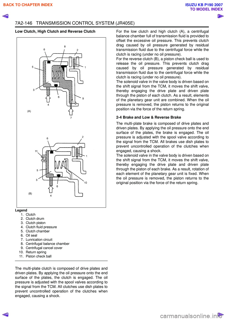
Low Clutch, High Clutch and Reverse Clutch
Legend1. Clutch
2. Clutch drum
3. Clutch piston
4. Clutch fluid pressure
5. Clutch chamber
6. Oil seal
7. Lunrication circuit
8. Centrifugal balance chamber
9. Centrifugal cancel cover
10. Return spring 11. Piston check ball
The multi-plate clutch is composed of drive plates and
driven plates. By applying the oil pressure onto the end
surface of the plates, the clutch is engaged. The oil
pressure is adjusted with the spool valves according to
the signal from the TCM. All clutches use dish plates to
prevent uncontrolled operation of the clutches when
engaged, causing a shock. For the low clutch and high clutch (A), a centrifugal
balance chamber full of transmission fluid is provided to
offset the excessive oil pressure. This prevents clutch
drag caused by oil pressure generated by residual
transmission fluid due to the centrifugal force while the
clutch is racing (under no oil pressure).
For the reverse clutch (B), a piston check ball is used to
release the oil pressure. This prevents clutch drag
caused by oil pressure generated by residual
transmission fluid due to the centrifugal force while the
clutch is racing (under no oil pressure).
The solenoid valve in the valve body is driven based on
the shift signal from the TCM, it moves the shift valve,
thereby engaging the drive plate and driven plate
through the piston of each clutch. As a result, elements
of the planetary gear unit are combined. When the oil
pressure is removed, the piston returns to the original
position via the force of the return spring.
2-4 Brake and Low & Reverse Brake
The multi-plate brake is composed of drive plates and
driven plates. By applying the oil pressure onto the end
surface of the plates, the brake is engaged. The oil
pressure is adjusted with the spool valve according to
the signal from the TCM. All brakes use dish plates to
prevent uncontrolled operation of the clutches when
engaged, causing a shock.
The solenoid valve in the valve body is driven based on
the shift signal from the TCM, it moves the shift valve,
thereby engaging the drive plate and driven plate
through the piston of each brake. As a result, rotation of
each element of the planetary gear unit is fixed. When
the oil pressure is removed, the piston returns to the
original position via the force of the return spring.
BACK TO CHAPTER INDEX
TO MODEL INDEX
ISUZU KB P190 2007
Page 4432 of 6020
7A2-148 TRANSMISSION CONTROL SYSTEM (JR405E)
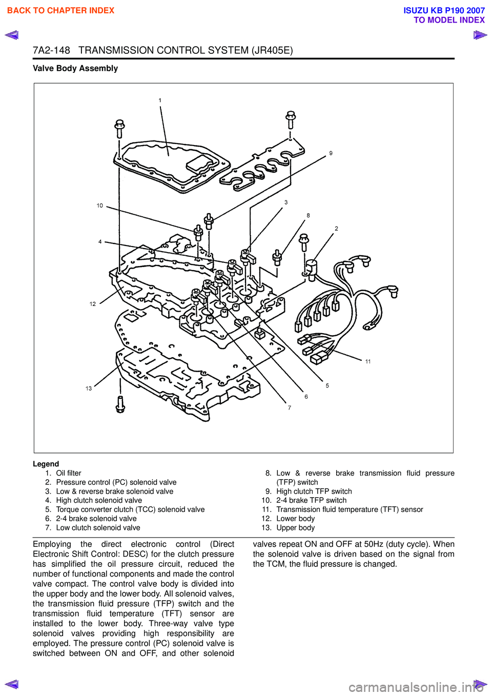
Valve Body Assembly
Legend1. Oil filter
2. Pressure control (PC) solenoid valve
3. Low & reverse brake solenoid valve
4. High clutch solenoid valve
5. Torque converter clutch (TCC) solenoid valve
6. 2-4 brake solenoid valve
7. Low clutch solenoid valve 8. Low & reverse brake transmission fluid pressure
(TFP) switch
9. High clutch TFP switch
10. 2-4 brake TFP switch
11. Transmission fluid temperature (TFT) sensor
12. Lower body
13. Upper body
Employing the direct electronic control (Direct
Electronic Shift Control: DESC) for the clutch pressure
has simplified the oil pressure circuit, reduced the
number of functional components and made the control
valve compact. The control valve body is divided into
the upper body and the lower body. All solenoid valves,
the transmission fluid pressure (TFP) switch and the
transmission fluid temperature (TFT) sensor are
installed to the lower body. Three-way valve type
solenoid valves providing high responsibility are
employed. The pressure control (PC) solenoid valve is
switched between ON and OFF, and other solenoid valves repeat ON and OFF at 50Hz (duty cycle). When
the solenoid valve is driven based on the signal from
the TCM, the fluid pressure is changed.
BACK TO CHAPTER INDEX
TO MODEL INDEX
ISUZU KB P190 2007
Page 4433 of 6020
TRANSMISSION CONTROL SYSTEM (JR405E) 7A2-149
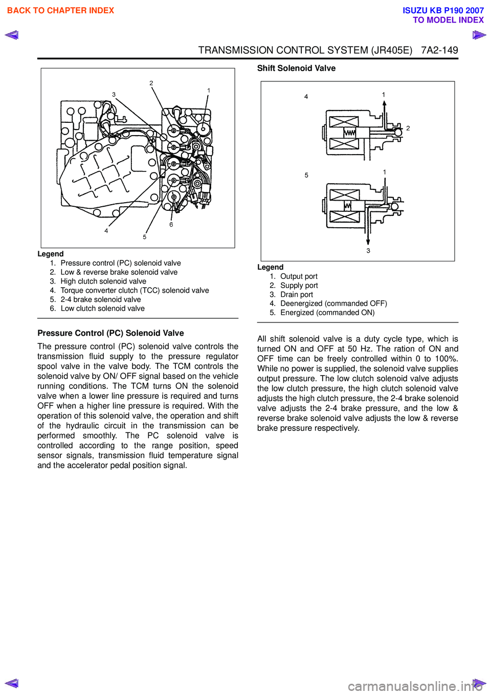
Legend1. Pressure control (PC) solenoid valve
2. Low & reverse brake solenoid valve
3. High clutch solenoid valve
4. Torque converter clutch (TCC) solenoid valve
5. 2-4 brake solenoid valve
6. Low clutch solenoid valve
Pressure Control (PC) Solenoid Valve
The pressure control (PC) solenoid valve controls the
transmission fluid supply to the pressure regulator
spool valve in the valve body. The TCM controls the
solenoid valve by ON/ OFF signal based on the vehicle
running conditions. The TCM turns ON the solenoid
valve when a lower line pressure is required and turns
OFF when a higher line pressure is required. With the
operation of this solenoid valve, the operation and shift
of the hydraulic circuit in the transmission can be
performed smoothly. The PC solenoid valve is
controlled according to the range position, speed
sensor signals, transmission fluid temperature signal
and the accelerator pedal position signal. Shift Solenoid Valve
Legend
1. Output port
2. Supply port
3. Drain port
4. Deenergized (commanded OFF)
5. Energized (commanded ON)
All shift solenoid valve is a duty cycle type, which is
turned ON and OFF at 50 Hz. The ration of ON and
OFF time can be freely controlled within 0 to 100%.
While no power is supplied, the solenoid valve supplies
output pressure. The low clutch solenoid valve adjusts
the low clutch pressure, the high clutch solenoid valve
adjusts the high clutch pressure, the 2-4 brake solenoid
valve adjusts the 2-4 brake pressure, and the low &
reverse brake solenoid valve adjusts the low & reverse
brake pressure respectively.
BACK TO CHAPTER INDEX
TO MODEL INDEX
ISUZU KB P190 2007
Page 4435 of 6020
TRANSMISSION CONTROL SYSTEM (JR405E) 7A2-151
The transmission fluid temperature (TFT) sensor is part
of the harness assembly. The sensor is a variable
resistor and it measures the temperature of the
transmission fluid. When the TFT sensor is cold, the
sensor resistance is high. When the transmission fluid
temperature increases, the sensor resistance
decreases. With high sensor resistance, the TCM
detects a high voltage on the signal circuit. With lower
sensor resistance, the TCM detects a lower voltage on
the signal circuit.
If the fluid temperature increases to 135 °C (275 °F), the
TCM illuminates A/T Oil Temp lamp on the instrument
panel cluster. When the fluid temperature deceases
below 125 °C (257 °F), the lamp goes off.
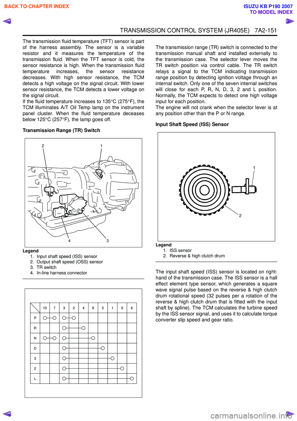
Transmission Range (TR) Switch
Legend 1. Input shaft speed (ISS) sensor
2. Output shaft speed (OSS) sensor
3. TR switch
4. In-line harness connector
The transmission range (TR) switch is connected to the
transmission manual shaft and installed externally to
the transmission case. The selector lever moves the
TR switch position via control cable. The TR switch
relays a signal to the TCM indicating transmission
range position by detecting ignition voltage through an
internal switch. Only one of the seven internal switches
will close for each P, R, N, D, 3, 2 and L position.
Normally, the TCM expects to detect one high voltage
input for each position.
The engine will not crank when the selector lever is at
any position other than the P or N range.
Input Shaft Speed (ISS) Sensor
Legend 1. ISS sensor
2. Reverse & high clutch drum
The input shaft speed (ISS) sensor is located on right-
hand of the transmission case. The ISS sensor is a hall
effect element type sensor, which generates a square
wave signal pulse based on the reverse & high clutch
drum rotational speed (32 pulses per a rotation of the
reverse & high clutch drum that is fitted with the input
shaft by spline). The TCM calculates the turbine speed
by the ISS sensor signal, and uses it to calculate torque
converter slip speed and gear ratio.
3
1
24
P
R
N
D
3
2
L
10732485196
1
2
BACK TO CHAPTER INDEX
TO MODEL INDEX
ISUZU KB P190 2007
Page 4436 of 6020
7A2-152 TRANSMISSION CONTROL SYSTEM (JR405E)
Output Shaft Speed (OSS) Sensor
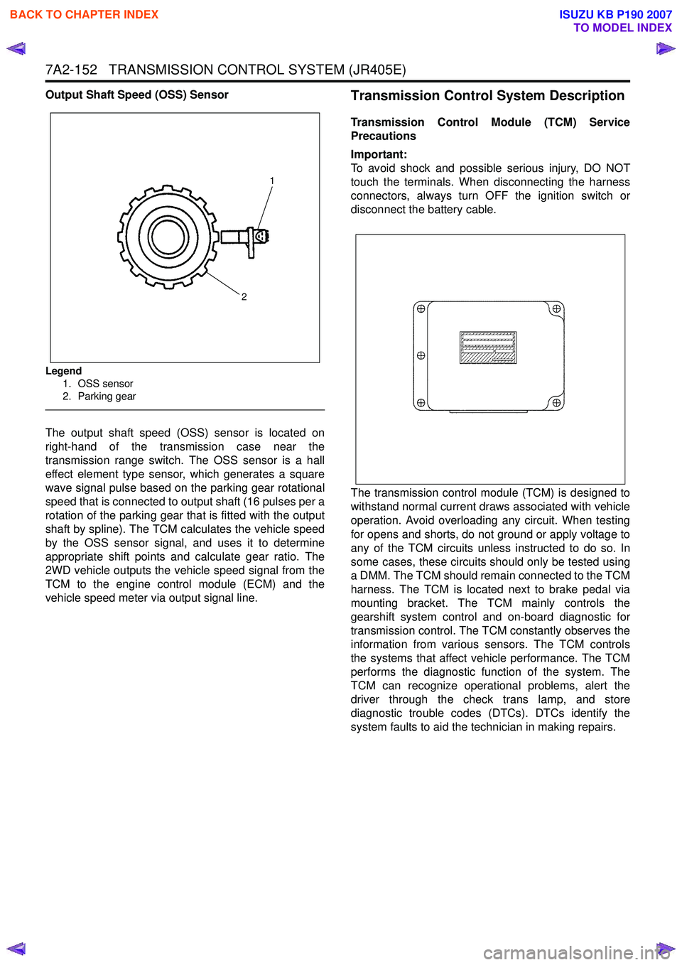
Legend1. OSS sensor
2. Parking gear
The output shaft speed (OSS) sensor is located on
right-hand of the transmission case near the
transmission range switch. The OSS sensor is a hall
effect element type sensor, which generates a square
wave signal pulse based on the parking gear rotational
speed that is connected to output shaft (16 pulses per a
rotation of the parking gear that is fitted with the output
shaft by spline). The TCM calculates the vehicle speed
by the OSS sensor signal, and uses it to determine
appropriate shift points and calculate gear ratio. The
2WD vehicle outputs the vehicle speed signal from the
TCM to the engine control module (ECM) and the
vehicle speed meter via output signal line.
Transmission Control System Description
Transmission Control Module (TCM) Service
Precautions
Important:
To avoid shock and possible serious injury, DO NOT
touch the terminals. When disconnecting the harness
connectors, always turn OFF the ignition switch or
disconnect the battery cable.
The transmission control module (TCM) is designed to
withstand normal current draws associated with vehicle
operation. Avoid overloading any circuit. When testing
for opens and shorts, do not ground or apply voltage to
any of the TCM circuits unless instructed to do so. In
some cases, these circuits should only be tested using
a DMM. The TCM should remain connected to the TCM
harness. The TCM is located next to brake pedal via
mounting bracket. The TCM mainly controls the
gearshift system control and on-board diagnostic for
transmission control. The TCM constantly observes the
information from various sensors. The TCM controls
the systems that affect vehicle performance. The TCM
performs the diagnostic function of the system. The
TCM can recognize operational problems, alert the
driver through the check trans lamp, and store
diagnostic trouble codes (DTCs). DTCs identify the
system faults to aid the technician in making repairs.
1
2
BACK TO CHAPTER INDEX
TO MODEL INDEX
ISUZU KB P190 2007
Page 4437 of 6020
TRANSMISSION CONTROL SYSTEM (JR405E) 7A2-153
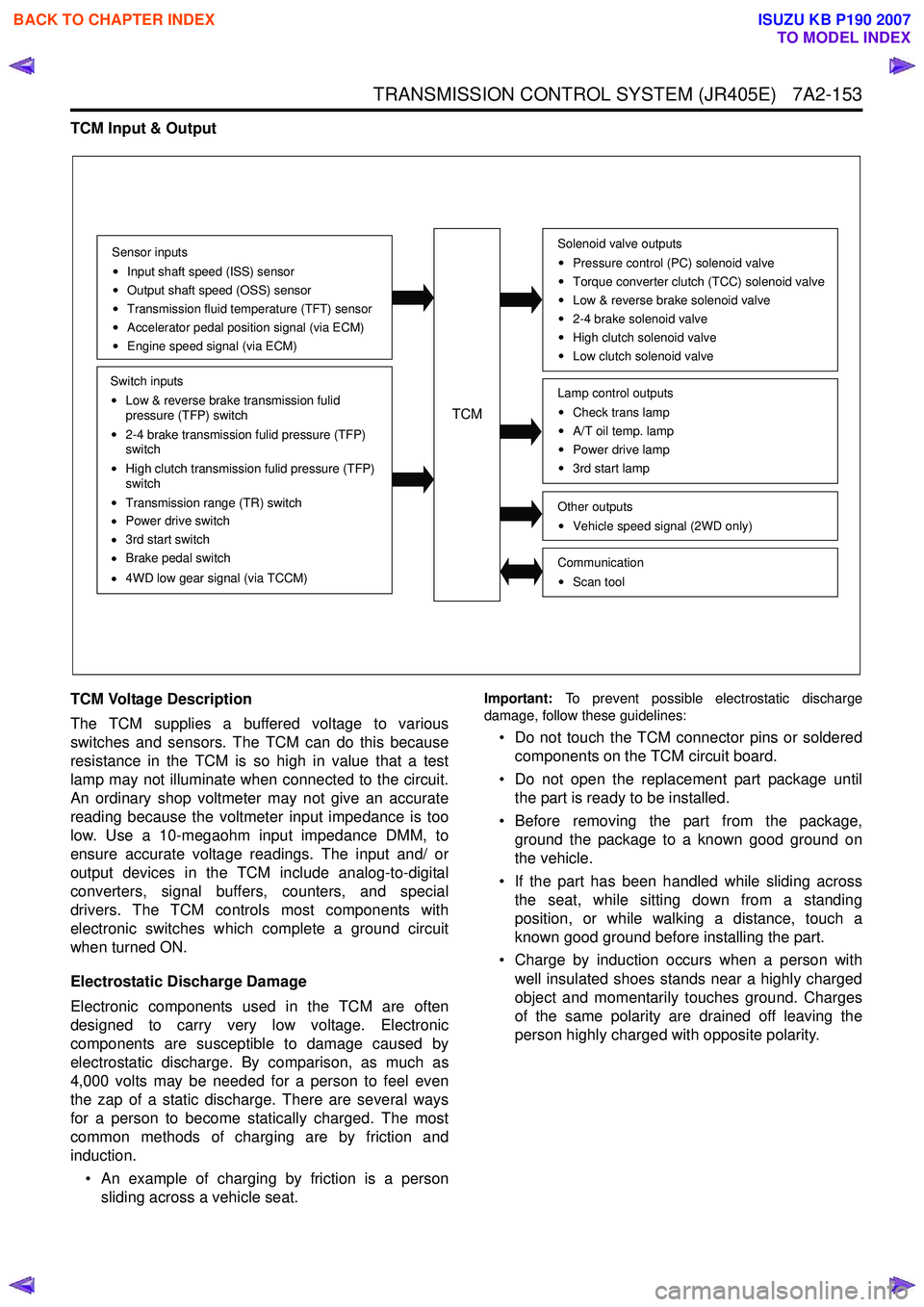
TCM Input & Output
TCM Voltage Description
The TCM supplies a buffered voltage to various
switches and sensors. The TCM can do this because
resistance in the TCM is so high in value that a test
lamp may not illuminate when connected to the circuit.
An ordinary shop voltmeter may not give an accurate
reading because the voltmeter input impedance is too
low. Use a 10-megaohm input impedance DMM, to
ensure accurate voltage readings. The input and/ or
output devices in the TCM include analog-to-digital
converters, signal buffers, counters, and special
drivers. The TCM controls most components with
electronic switches which complete a ground circuit
when turned ON.
Electrostatic Discharge Damage
Electronic components used in the TCM are often
designed to carry very low voltage. Electronic
components are susceptible to damage caused by
electrostatic discharge. By comparison, as much as
4,000 volts may be needed for a person to feel even
the zap of a static discharge. There are several ways
for a person to become statically charged. The most
common methods of charging are by friction and
induction.
• An example of charging by friction is a person sliding across a vehicle seat.
Important: To prevent possible electrostatic discharge
damage, follow these guidelines:
• Do not touch the TCM connector pins or soldered components on the TCM circuit board.
• Do not open the replacement part package until the part is ready to be installed.
• Before removing the part from the package, ground the package to a known good ground on
the vehicle.
• If the part has been handled while sliding across the seat, while sitting down from a standing
position, or while walking a distance, touch a
known good ground before installing the part.
• Charge by induction occurs when a person with well insulated shoes stands near a highly charged
object and momentarily touches ground. Charges
of the same polarity are drained off leaving the
person highly charged with opposite polarity.
Sensor inputs
Input shaft speed (ISS) sensor
Output shaft speed (OSS) sensor
Transmission fluid temperature (TFT) sensor
Accelerator pedal position signal (via ECM)
Engine speed signal (via ECM)
Switch inputs
Low & reverse brake transmission fulid
pressure (TFP) switch
2-4 brake transmission fulid pressure (TFP)
switch
High clutch transmission fulid pressure (TFP)
switch
Transmission range (TR) switch
Power drive switch
3rd start switch
Brake pedal switch
4WD low gear signal (via TCCM)
TCM
Solenoid valve outputs
Pressure control (PC) solenoid valve
Torque converter clutch (TCC) solenoid valve
Low & reverse brake solenoid valve
2-4 brake solenoid valve
High clutch solenoid valve
Low clutch solenoid valve
Other outputsVehicle speed signal (2WD only)
CommunicationScan tool
Lamp control outputsCheck trans lamp
A/T oil temp. lamp
Power drive lamp
3rd start lamp
BACK TO CHAPTER INDEX
TO MODEL INDEX
ISUZU KB P190 2007
Page 4439 of 6020
TRANSMISSION CONTROL SYSTEM (JR405E) 7A2-155
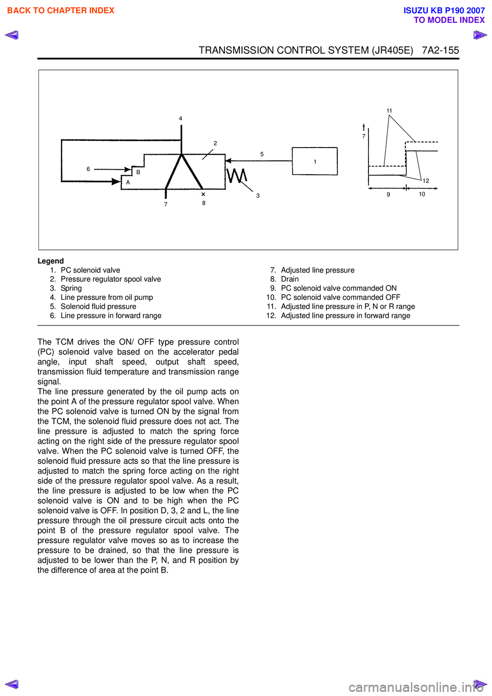
Legend1. PC solenoid valve
2. Pressure regulator spool valve
3. Spring
4. Line pressure from oil pump
5. Solenoid fluid pressure
6. Line pressure in forward range 7. Adjusted line pressure
8. Drain
9. PC solenoid valve commanded ON
10. PC solenoid valve commanded OFF 11. Adjusted line pressure in P, N or R range
12. Adjusted line pressure in forward range
The TCM drives the ON/ OFF type pressure control
(PC) solenoid valve based on the accelerator pedal
angle, input shaft speed, output shaft speed,
transmission fluid temperature and transmission range
signal.
The line pressure generated by the oil pump acts on
the point A of the pressure regulator spool valve. When
the PC solenoid valve is turned ON by the signal from
the TCM, the solenoid fluid pressure does not act. The
line pressure is adjusted to match the spring force
acting on the right side of the pressure regulator spool
valve. When the PC solenoid valve is turned OFF, the
solenoid fluid pressure acts so that the line pressure is
adjusted to match the spring force acting on the right
side of the pressure regulator spool valve. As a result,
the line pressure is adjusted to be low when the PC
solenoid valve is ON and to be high when the PC
solenoid valve is OFF. In position D, 3, 2 and L, the line
pressure through the oil pressure circuit acts onto the
point B of the pressure regulator spool valve. The
pressure regulator valve moves so as to increase the
pressure to be drained, so that the line pressure is
adjusted to be lower than the P, N, and R position by
the difference of area at the point B.
11
7
12
4
6 B
A 2
7 8 3 1
5
910
BACK TO CHAPTER INDEX
TO MODEL INDEX
ISUZU KB P190 2007
Page 4458 of 6020
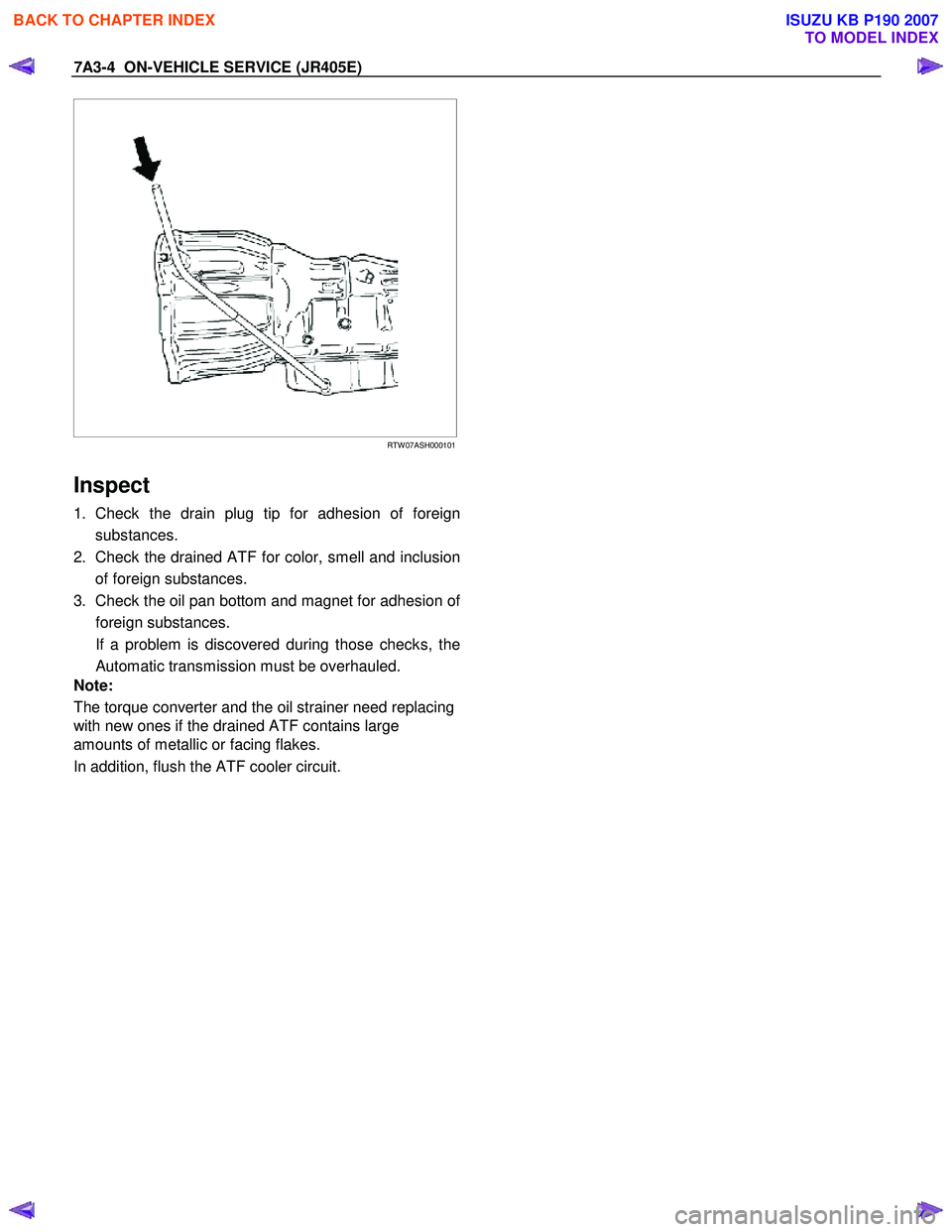
7A3-4 ON-VEHICLE SERVICE (JR405E)
RTW 07ASH000101
Inspect
1. Check the drain plug tip for adhesion of foreign
substances.
2. Check the drained ATF for color, smell and inclusion of foreign substances.
3. Check the oil pan bottom and magnet for adhesion o
f
foreign substances.
If a problem is discovered during those checks, the Automatic transmission must be overhauled.
Note:
The torque converter and the oil strainer need replacing
with new ones if the drained ATF contains large
amounts of metallic or facing flakes.
In addition, flush the ATF cooler circuit.
BACK TO CHAPTER INDEX
TO MODEL INDEX
ISUZU KB P190 2007
Page 4462 of 6020

7A3-8 ON-VEHICLE SERVICE (JR405E)
SPEED SENSOR
The speed sensor is attached to the right side of the
transmission.
240L300001
Legend
1. Inhibitor switch
2. Speed sensor
3. Turbine sensor
Inspect
1. During driving at a speed of 20km/h (12mph) with “L”
range in low gear, measure the voltage between the
TCM connector terminals (B13) and (B5) with a
digital voltmeter.
Standard voltage : approx. 7V (AC range)
RTW 47ASH000801
2. If the voltage is outside of the standard value, check
the speed sensor pole piece for the presence o
f
foreign materials and the speeed sensor cable for a
short or open circuit.
If the result of the inspection is normal, replace the speed sensor.
Torque: 6 N·m (0.6 kgf·m/52 lb·in)
BACK TO CHAPTER INDEX
TO MODEL INDEX
ISUZU KB P190 2007