lug pattern ISUZU KB P190 2007 Workshop Repair Manual
[x] Cancel search | Manufacturer: ISUZU, Model Year: 2007, Model line: KB P190, Model: ISUZU KB P190 2007Pages: 6020, PDF Size: 70.23 MB
Page 280 of 6020
POWER-ASSISTED STEERING SYSTEM 3B-19
Disassembly
1. Clean the oil pump with solvent (plug the discharge
and suction ports to prevent the entry of solvent).
Be careful not to expose the oil seal of shaft
assembly to solvent.
2. Remove the bolt, suction pipe and O-ring.
3. Remove the connector, O-ring, relief valve and spring.
4. Remove the bolt, rear housing and O-ring.
5. Remove the snap ring.
6. Remove the shaft assembly.
7. Remove the oil seal.
CAUTION: When removing the oil seal, be careful
not to damage the housing.
8. Remove the pump cartridge assembly from the front housing.
9. Remove two O-rings.
Inspection and Repair
Make all necessary adjustments, repairs, and part
replacements if wear, damage, or other problems are
discovered during inspection.
Rotor
442RS002
Check that the groove in the vane is free from excessive
wear and that the vane slides smoothly. W hen part
replacement becomes necessary, the pump cartridge
should be replaced as a subassembly.
Vane
442RS003
Sliding faces of the vane should be free from wear.
(Particularly the curved face at the tip that contact with
the cam should be free from wear and distortion). W hen
part replacement becomes necessary, the pump
cartridge should be replaced as a subassembly.
Cam
The inner face of the cam should have a uniform
contact pattern without a sign of step wear. W hen part
replacement becomes necessary, the pump cartridge
should be replaced as a subassembly.
Side Plate
The sliding faces of parts must be free from step wear
(more than 0.01 mm (0.0004 in)), which can be felt b
y
the finger nail.
The parts with minor scores may be reused after lapping
the face.
Relief Valve
The sliding face of the valve must be free from burrs
and damage. The parts with minor scores may be
reused after smoothing with emery cloth (#800 or finer).
Shaft
Oil seal sliding faces must be free from a step wear
which can be felt by the finger nail. Bushing fitting face
must be free from damage and wear.
O-ring, Oil Seal, Snap Ring
Be sure to discard used parts, and always use new
parts for installation. Prior to installation, lubricate all
seals and rings with power steering fluid.
BACK TO CHAPTER INDEX
TO MODEL INDEX
ISUZU KB P190 2007
Page 285 of 6020
3B-24 POWER-ASSISTED STEERING SYSTEM
Disassembly
1. Clean the oil pump with solvent (plug the discharge
and suction ports to prevent the entry of solvent).
Be careful not to expose the oil seal of the shaft assembly to solvent.
2. Remove the bolt, suction pipe and O-ring.
3. Remove the nut and bracket.
4. Remove the nut, washer and joint.
5. Remove the connector, O-ring, relief valve and spring.
6. Remove the bolt, rear housing and O-ring.
7. Remove the pump cartridge assembly and the side plate from the shaft. Remove two O-rings.
Inspection and Repair
Make all necessary adjustments, repairs, and part
replacements if wear, damage, or other problems are
discovered during inspection.
Rotor
442RS002
Check that the groove in the vane is free from excessive
wear and that the vane slides smoothly. W hen part
replacement becomes necessary, the pump cartridge
should be replaced as a subassembly.
Vane
442RS003
Sliding faces of the vane should be free from wear. (In
particular the curved face at the tip that makes contact
with the cam should be free from wear and distortion).
W hen part replacement becomes necessary, the pump
cartridge should be replaced as a subassembly.
Cam
The inner face of the cam should have a uniform
contact pattern without a sign of step wear. W hen part
replacement becomes necessary, the pump cartridge
should be replaced as a subassembly.
Side Plate
The sliding faces of parts must be free from step wear
(more than 0.01 mm (0.0004 in)), which can be felt by a
finger nail.
Parts with minor scores may be reused after lapping the
face.
Relief Valve
The sliding face of the valve must be free from burrs
and damage. Parts with minor scores may be reused
after smoothing with emery cloth (#800 or finer).
Shaft and Housing Assembly
The bushing fitting face on the shaft must be free from
damage and wear.
O-ring
Be sure to discard used parts, and always use new
parts for installation. Prior to installation, lubricate all
seals and rings with power steering fluid.
BACK TO CHAPTER INDEX
TO MODEL INDEX
ISUZU KB P190 2007
Page 1300 of 6020
6E-266 Engine Control System (4JH1)
Lack of Power, Sluggishness, Sponginess
Checks Action
DEFINITION:The engine delivers less than expected power. There is little or no increase in speed when partially applying the
accelerator pedal.
Preliminary Checks • Diagnostic System Check - Engine Controls.
• Compare the vehicle with a similar unit. Ensure the vehicle has an actual problem.
• Remove the air cleaner and check for dirt, or for air ducts being plugged or
restricted. Replace as necessary.
• Have the tire sizes changed?
• Are excessively heavy loads being carried?
• Inspect for clutch slip.
• Inspect brake drag.
• Inspect for a proper transmission shift pattern and down shift operation (A/T only).
• Inspect the fuel quality (cetane index).
• Inspect the engine oil level and quality.
• Use the scan tool in order to make sure the Vehicle Speed parameter reading
matches the vehicle speedometer.
• Inspect the engine control module (ECM) and fuel injection pump control unit (PCU)
grounds for being clean, tight, and in their proper locations.
• Inspect the scan tool Data List in this section.
• Inspect the Service Bulletins for ECM software updates.
Sensor Checks Inspect the engine control sensors for the following conditions. Refer to the scan tool
Data List in this section.
• Use the scan tool to compare the Engine Coolant Temperature (ECT) with the Intake
Air Temperature (IAT) and Fuel Temperature (FT) on a cold engine condition. If the
difference among temperature reading is more than 5°C (9°F) on a cold engine,
check for high resistance on the low reference circuit and signal circuit or for a
skewed sensor.
Notice: The mass air flow (MAF) sensor is heated and as a result the IAT sensor may
indicate a higher than normal intake air temperature if the ignition switch is being
ON. FT sensor is internal to the PCU and it is part of the fuel injection pump
assembly.
• Use the scan tool to compare the MAF Sensor parameter with the Desired MAF
parameter. Start the engine and warm up (allow engine coolant temperature to reach
at least 60°C [140°F]). The MAF Sensor parameter must follow the Desired MAF
parameter within 100 mg/strk. If not, inspect the air intake system, EGR system
components and contaminated, skewed or slow MAF sensor.
• Use the scan tool to observe the Accelerator Pedal Position Accelerator Pedal
Position. Accelerator Pedal Position parameter should change linearly from 0% to
100% according to the accelerator pedal operation.
BACK TO CHAPTER INDEX
TO MODEL INDEX
ISUZU KB P190 2007
Page 1302 of 6020

6E-268 Engine Control System (4JH1)
Checks Action
Engine Mechanical Check Inspect the engine mechanical for the following conditions. Refer to the Engine
Mechanical section.
• Inspect for poor cylinder compression. Proper compression is more than 2100 kPa
(309 psi).
• Improper mechanical timing
• Improper valve gap
• Broken or weak valve springs
• W orn camshaft lobes
Additional Checks •
Inspect the generator output voltage. Repair if less than 9 volts or more than 16
volts.
• Inspect the EGR system operating correctly.
• Inspect the engine overheat condition. Refer to the Engine Cooling section.
• Inspect the A/C operation.
• Inspect the torque converter clutch (TCC) operation (A/T only).
Hesitation, Sag, Stumble
Checks Action
DEFINITION:The vehicle has a momentary lack of response when pushing down on the accelerator. The condition can occur
at any vehicle speed. The condition is usually most severe when trying to make the vehicle move from a stop. If severe
enough, the condition may cause the engine to stall.
Preliminary Checks • Diagnostic System Check - Engine Controls.
• Compare the vehicle with a similar unit. Ensure the vehicle has an actual problem.
• Remove the air cleaner and check for dirt, or for air ducts being plugged or
restricted. Replace as necessary.
• Inspect for a proper transmission shift pattern and down shift operation.
• Inspect the fuel quality (cetane index).
• Inspect the engine oil level and quality.
• Inspect the scan tool Data List in this section.
• Inspect the engine control module (ECM) and fuel injection pump control unit (PCU)
grounds for being clean, tight, and in their proper locations.
• Inspect the Service Bulletins for ECM software updates.
Sensor Checks Inspect the engine control sensors for the following conditions. Refer to the scan tool
Data List in this section.
• Use the scan tool to compare the Engine Coolant Temperature (ECT) with the Intake
Air Temperature (IAT) and Fuel Temperature (FT) on a cold engine condition. If the
difference among temperature reading is more than 5°C (9°F) on a cold engine,
check for high resistance on the low reference circuit and signal circuit or for a
skewed sensor.
Notice: The mass air flow (MAF) sensor is heated and as a result the IAT sensor may
indicate a higher than normal intake air temperature if the ignition switch is being ON.
FT sensor is internal to the PCU and it is part of the fuel injection pump assembly.
• Use the scan tool to compare the MAF Sensor parameter with the Desired MAF
parameter. Start the engine and warm up (allow engine coolant temperature to reach
at least 60°C [140°F]). The MAF Sensor parameter must follow the Desired MAF
parameter within 100 mg/strk. If not, inspect the air intake system, EGR system
components and contaminated, skewed or slow MAF sensor.
• Use the scan tool to observe the Accelerator Pedal Position Accelerator Pedal
Position. Accelerator Pedal Position parameter should change linearly from 0% to
100% according to the accelerator pedal operation.
BACK TO CHAPTER INDEX
TO MODEL INDEX
ISUZU KB P190 2007
Page 1305 of 6020
Engine Control System (4JH1) 6E-271
Checks Action
Engine Mechanical Checks Inspect the engine mechanical for the following conditions. Refer to the Engine
Mechanical section.
• Inspect for poor cylinder compression. Proper compression is more than 2100 kPa
(309 psi).
• Inspect for incorrect basic engine parts such as camshaft, cylinder head, pistons,
etc.
• Inspect for any excessive oil entering combustion chamber.
Additional Checks •
Inspect the EGR system operating correctly.
• Inspect other possible causes that can make similar noise such as loose component
parts, bracket, mount and weak clutch damper spring.
Poor Fuel Economy
Checks Action
DEFINITION:Fuel economy, as measured by actual road tests and several tanks of fuel, is noticeably lower than expected.
Also, the economy is noticeably lower than it was on this vehicle at one time, as previously shown by actual road tests.
Preliminary Checks • Remove the air cleaner and check for dirt, or for air ducts being plugged or
restricted. Replace as necessary.
• Inspect the driving habits of the owner.
• Is the A/C ON full time, defroster mode ON?
• Are the tires at the correct pressure?
• Are the tire sizes changed?
• Are excessively heavy loads being carried?
• Is the acceleration too much, too often?
• Inspect for clutch slip.
• Inspect brake drag.
• Inspect dive belt tension.
• Inspect for a proper transmission shift pattern and down shift operation (A/T only).
• Inspect the fuel quality (cetane index).
• Inspect the engine oil level and quality.
• Suggest to the owner to fill the fuel tank and recheck the fuel economy.
• Suggest to the driver to read the Important Facts on Fuel Economy in the Owner
Manual.
• Inspect the odometer is correctly operated.
• Inspect the Service Bulletins for ECM software updates.
Sensor Checks Inspect the engine control sensors for the following conditions. Refer to the scan tool
Data List in this section.
• Use the scan tool to compare the Engine Coolant Temperature (ECT) with the Intake
Air Temperature (IAT) and Fuel Temperature (FT) on a cold engine condition. If the
difference among temperature reading is more than 5°C (9°F) on a cold engine,
check for high resistance on the low reference circuit and signal circuit or for a
skewed sensor.
Notice: The mass air flow (MAF) sensor is heated and as a result the IAT sensor may
indicate a higher than normal intake air temperature if the ignition switch is being ON.
FT sensor is internal to the PCU and it is part of the fuel injection pump assembly.
Fuel System Checks Inspect the fuel system for the following conditions. Refer to the Fuel System section.
• Inspect the fuel type and quality.
• Check fuel leak.
Cooling System Checks Inspect the cooling system for the following conditions. Refer to the Cooling System
Section.
• Inspect the engine coolant level.
• Inspect the engine thermostat for always being open or for the wrong heat range.
• Inspect the engine cooling fan for always being ON.
BACK TO CHAPTER INDEX
TO MODEL INDEX
ISUZU KB P190 2007
Page 1953 of 6020
6E-336 ENGINE CONTROL SYSTEM (4JK1/4JJ1)
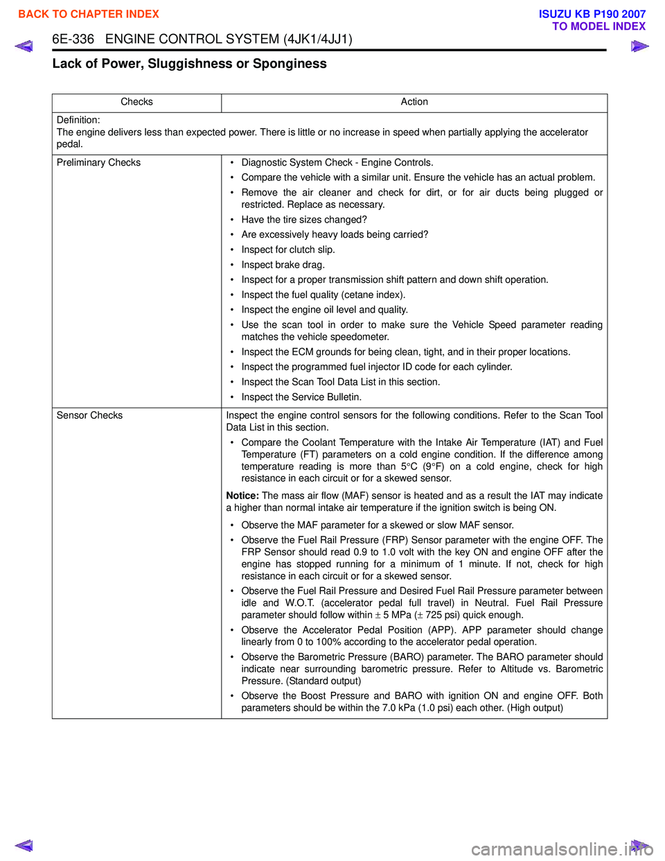
Lack of Power, Sluggishness or Sponginess
ChecksAction
Definition:
The engine delivers less than expected power. There is little or no increase in speed when partially applying the accelerator
pedal.
Preliminary Checks • Diagnostic System Check - Engine Controls.
• Compare the vehicle with a similar unit. Ensure the vehicle has an actual problem.
• Remove the air cleaner and check for dirt, or for air ducts being plugged or restricted. Replace as necessary.
• Have the tire sizes changed?
• Are excessively heavy loads being carried?
• Inspect for clutch slip.
• Inspect brake drag.
• Inspect for a proper transmission shift pattern and down shift operation.
• Inspect the fuel quality (cetane index).
• Inspect the engine oil level and quality.
• Use the scan tool in order to make sure the Vehicle Speed parameter reading matches the vehicle speedometer.
• Inspect the ECM grounds for being clean, tight, and in their proper locations.
• Inspect the programmed fuel injector ID code for each cylinder.
• Inspect the Scan Tool Data List in this section.
• Inspect the Service Bulletin.
Sensor Checks Inspect the engine control sensors for the following conditions. Refer to the Scan Tool
Data List in this section.
• Compare the Coolant Temperature with the Intake Air Temperature (IAT) and Fuel Temperature (FT) parameters on a cold engine condition. If the difference among
temperature reading is more than 5 °C (9 °F) on a cold engine, check for high
resistance in each circuit or for a skewed sensor.
Notice: The mass air flow (MAF) sensor is heated and as a result the IAT may indicate
a higher than normal intake air temperature if the ignition switch is being ON.
• Observe the MAF parameter for a skewed or slow MAF sensor.
• Observe the Fuel Rail Pressure (FRP) Sensor parameter with the engine OFF. The FRP Sensor should read 0.9 to 1.0 volt with the key ON and engine OFF after the
engine has stopped running for a minimum of 1 minute. If not, check for high
resistance in each circuit or for a skewed sensor.
• Observe the Fuel Rail Pressure and Desired Fuel Rail Pressure parameter between idle and W.O.T. (accelerator pedal full travel) in Neutral. Fuel Rail Pressure
parameter should follow within ± 5 MPa ( ± 725 psi) quick enough.
• Observe the Accelerator Pedal Position (APP). APP parameter should change linearly from 0 to 100% according to the accelerator pedal operation.
• Observe the Barometric Pressure (BARO) parameter. The BARO parameter should indicate near surrounding barometric pressure. Refer to Altitude vs. Barometric
Pressure. (Standard output)
• Observe the Boost Pressure and BARO with ignition ON and engine OFF. Both parameters should be within the 7.0 kPa (1.0 psi) each other. (High output)
BACK TO CHAPTER INDEX
TO MODEL INDEX
ISUZU KB P190 2007
Page 1955 of 6020
6E-338 ENGINE CONTROL SYSTEM (4JK1/4JJ1)
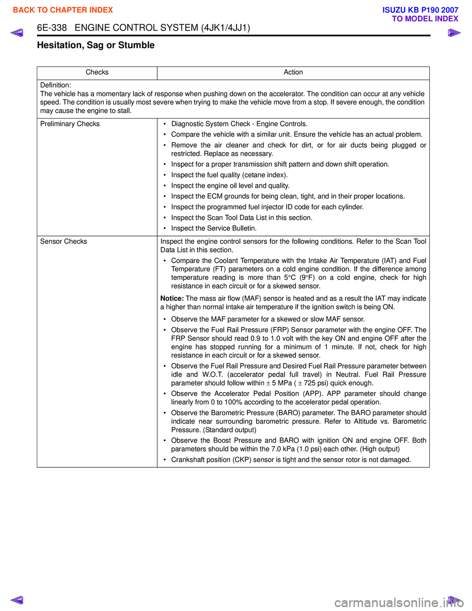
Hesitation, Sag or Stumble
ChecksAction
Definition:
The vehicle has a momentary lack of response when pushing down on the accelerator. The condition can occur at any vehicle
speed. The condition is usually most severe when trying to make the vehicle move from a stop. If severe enough, the condition
may cause the engine to stall.
Preliminary Checks • Diagnostic System Check - Engine Controls.
• Compare the vehicle with a similar unit. Ensure the vehicle has an actual problem.
• Remove the air cleaner and check for dirt, or for air ducts being plugged or restricted. Replace as necessary.
• Inspect for a proper transmission shift pattern and down shift operation.
• Inspect the fuel quality (cetane index).
• Inspect the engine oil level and quality.
• Inspect the ECM grounds for being clean, tight, and in their proper locations.
• Inspect the programmed fuel injector ID code for each cylinder.
• Inspect the Scan Tool Data List in this section.
• Inspect the Service Bulletin.
Sensor Checks Inspect the engine control sensors for the following conditions. Refer to the Scan Tool
Data List in this section.
• Compare the Coolant Temperature with the Intake Air Temperature (IAT) and Fuel Temperature (FT) parameters on a cold engine condition. If the difference among
temperature reading is more than 5 °C (9 °F) on a cold engine, check for high
resistance in each circuit or for a skewed sensor.
Notice: The mass air flow (MAF) sensor is heated and as a result the IAT may indicate
a higher than normal intake air temperature if the ignition switch is being ON.
• Observe the MAF parameter for a skewed or slow MAF sensor.
• Observe the Fuel Rail Pressure (FRP) Sensor parameter with the engine OFF. The FRP Sensor should read 0.9 to 1.0 volt with the key ON and engine OFF after the
engine has stopped running for a minimum of 1 minute. If not, check for high
resistance in each circuit or for a skewed sensor.
• Observe the Fuel Rail Pressure and Desired Fuel Rail Pressure parameter between idle and W.O.T. (accelerator pedal full travel) in Neutral. Fuel Rail Pressure
parameter should follow within ± 5 MPa ( ± 725 psi) quick enough.
• Observe the Accelerator Pedal Position (APP). APP parameter should change linearly from 0 to 100% according to the accelerator pedal operation.
• Observe the Barometric Pressure (BARO) parameter. The BARO parameter should indicate near surrounding barometric pressure. Refer to Altitude vs. Barometric
Pressure. (Standard output)
• Observe the Boost Pressure and BARO with ignition ON and engine OFF. Both parameters should be within the 7.0 kPa (1.0 psi) each other. (High output)
• Crankshaft position (CKP) sensor is tight and the sensor rotor is not damaged.
BACK TO CHAPTER INDEX
TO MODEL INDEX
ISUZU KB P190 2007
Page 1958 of 6020
ENGINE CONTROL SYSTEM (4JK1/4JJ1) 6E-341
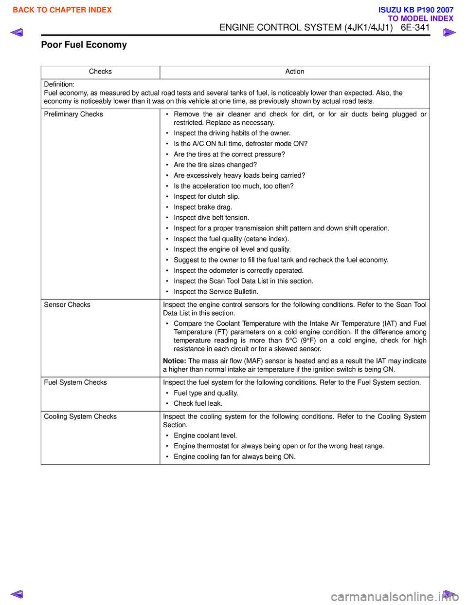
Poor Fuel Economy
ChecksAction
Definition:
Fuel economy, as measured by actual road tests and several tanks of fuel, is noticeably lower than expected. Also, the
economy is noticeably lower than it was on this vehicle at one time, as previously shown by actual road tests.
Preliminary Checks • Remove the air cleaner and check for dirt, or for air ducts being plugged or
restricted. Replace as necessary.
• Inspect the driving habits of the owner.
• Is the A/C ON full time, defroster mode ON?
• Are the tires at the correct pressure?
• Are the tire sizes changed?
• Are excessively heavy loads being carried?
• Is the acceleration too much, too often?
• Inspect for clutch slip.
• Inspect brake drag.
• Inspect dive belt tension.
• Inspect for a proper transmission shift pattern and down shift operation.
• Inspect the fuel quality (cetane index).
• Inspect the engine oil level and quality.
• Suggest to the owner to fill the fuel tank and recheck the fuel economy.
• Inspect the odometer is correctly operated.
• Inspect the Scan Tool Data List in this section.
• Inspect the Service Bulletin.
Sensor Checks Inspect the engine control sensors for the following conditions. Refer to the Scan Tool
Data List in this section.
• Compare the Coolant Temperature with the Intake Air Temperature (IAT) and Fuel Temperature (FT) parameters on a cold engine condition. If the difference among
temperature reading is more than 5 °C (9 °F) on a cold engine, check for high
resistance in each circuit or for a skewed sensor.
Notice: The mass air flow (MAF) sensor is heated and as a result the IAT may indicate
a higher than normal intake air temperature if the ignition switch is being ON.
Fuel System Checks Inspect the fuel system for the following conditions. Refer to the Fuel System section.
• Fuel type and quality.
• Check fuel leak.
Cooling System Checks Inspect the cooling system for the following conditions. Refer to the Cooling System
Section.
• Engine coolant level.
• Engine thermostat for always being open or for the wrong heat range.
• Engine cooling fan for always being ON.
BACK TO CHAPTER INDEX
TO MODEL INDEX
ISUZU KB P190 2007
Page 2547 of 6020
Engine Mechanical – V6 Page 6A1–68
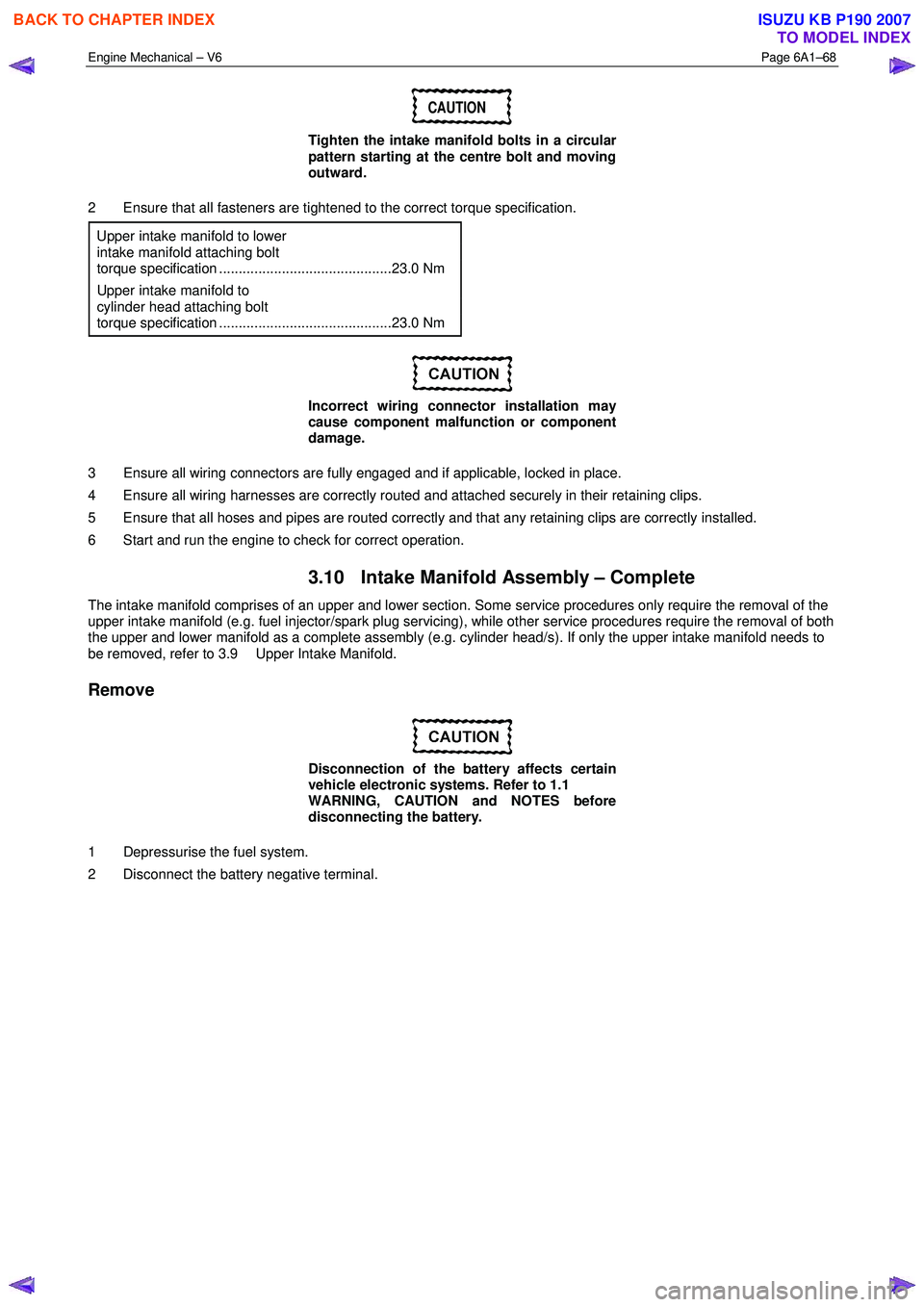
CAUTION
Tighten the intake manifold bolts in a circular
pattern starting at the centre bolt and moving
outward.
2 Ensure that all fasteners are tightened to the correct torque specification. Upper intake manifold to lower
intake manifold attaching bolt
torque specification ............................................23.0 Nm
Upper intake manifold to
cylinder head attaching bolt
torque specification ............................................23.0 Nm
Incorrect wiring connector installation may
cause component malfunction or component
damage.
3 Ensure all wiring connectors are fully engaged and if applicable, locked in place.
4 Ensure all wiring harnesses are correctly routed and attached securely in their retaining clips.
5 Ensure that all hoses and pipes are routed correctly and that any retaining clips are correctly installed.
6 Start and run the engine to check for correct operation.
3.10 Intake Manifold Assembly – Complete
The intake manifold comprises of an upper and lower section. Some service procedures only require the removal of the
upper intake manifold (e.g. fuel injector/spark plug servicing), while other service procedures require the removal of both
the upper and lower manifold as a complete assembly (e.g. cylinder head/s). If only the upper intake manifold needs to
be removed, refer to 3.9 Upper Intake Manifold.
Remove
Disconnection of the battery affects certain
vehicle electronic systems. Refer to 1.1
WARNING, CAUTION and NOTES before
disconnecting the battery.
1 Depressurise the fuel system.
2 Disconnect the battery negative terminal.
BACK TO CHAPTER INDEX
TO MODEL INDEX
ISUZU KB P190 2007
Page 3245 of 6020
Engine Management – V6 – General Information Page 6C1-1–3
1 General Information
The V6 engine management system
incorporates functions and components that
could cause personal injury or vehicle
damage. Refer to 6C1-2 Engine Management –
V6 – Diagnostics, and 6C1-3 Engine
Management – V6 – Service Operations,
before attempting any diagnosis or repairs.
1.1 Introduction
The V6 engine management system is designed to improve engine performance and increase vehicle safety while
meeting the stringent Euro 3 vehicle emission standard. This is achieved by the introduction of the following engine
management sub-systems and components:
• Throttle actuator control (TAC) System – the TAC system allows the engine control module (ECM) to electronically
control the throttle plate opening eliminating the need for the following components:
• mechanical link between the throttle plate and accelerator pedal,
• cruise control module, and
• idle air control motor.
Refer to 3.5 Throttle Actuator Control System for details of the TAC System operation and to 3.6 Cruise Control System for details of the cruise control operation.
This feature results in improved driveability, better fuel economy and emission control.
• W ide band heated oxygen sensor provides a more accurate measurement of the oxygen concentration in the
exhaust gas. Refer to 4.14 Heated Oxygen Sensors.
• Dual spray fuel injectors are now used. The use of this spray pattern is used in engines with two intake valves per
cylinder. The dual spray is achieved by having two openings in the spray orifice disc that are arranged in such a
way that two fuel sprays result, being aimed at each intake valve port. Refer to 4.12 Fuel Injectors.
• Pencil Coil – allows the ignition coil to be fitted directly on the spark plug eliminating the need for spark plug wires.
Refer to 4.15 Ignition Coil and Spark Plug.
The engine management system has a self diagnostic capability, as well as connections to enable diagnosis of faults. If
the ECM recognises operational problems it can alert the driver via the malfunction indicator lamp (MIL) in the instrument
cluster. The ECM also interfaces with other systems in the vehicle as required.
For further information on the air-conditioning system refer to 2A Heater and Air-conditioning,
For the location of fuses, fusible links and relays, refer to 8A Electrical-Body and Chassis.
1.2 Emission Control
ADR 79/01 Emissions Standards
MY2006 I190 Rodeo has been configured to comply with Australian Design Rule 79/01, that adopts the technical
requirements of the European Council Directive 98/69/EC. Commonly referred to as “Euro 3”, the new legislation
modifies the exhaust emissions, compared to the existing ADR 37/01 (or ‘Euro 2’) vehicle emissions standards.
Australian Design Rule 79/01 implements the 'Euro 3' exhaust and evaporative emissions requirements for petrol fuelled
passenger cars, forward control vehicles and passenger off-road vehicles with a gross vehicle mass (GVM) up to 3.5
tonnes. All new vehicles within these categories and first registered from January 1, 2006 must comply with ADR 79/01.
The next table shows a comparison between the existing ADR 37/01 (‘Euro 2’) and ADR 79/01 (‘Euro 3’) Hydrocarbons
Carbon
Monoxide (g/km) Exhaust
(g/km) Evaporative
(g/test) Oxides of Nitrogen
(g/km) Particulate
Matter (g/test)
BACK TO CHAPTER INDEX
TO MODEL INDEX
ISUZU KB P190 2007