diagram ISUZU KB P190 2007 Workshop User Guide
[x] Cancel search | Manufacturer: ISUZU, Model Year: 2007, Model line: KB P190, Model: ISUZU KB P190 2007Pages: 6020, PDF Size: 70.23 MB
Page 1035 of 6020
Engine Control System (4JH1) 6E-1
SECTION 6E
ENGINE CONTROL SYSTEM (4JH1)
TABLE OF CONTENTS
Specifications ..................................................... 6E-4
Schematic And Routing Diagrams ..................... 6E-5 Vacuum Hose Routing Diagram...................... 6E-5
Engine Controls Schematics ........................... 6E-7
Component Locator ............................................ 6E-18 Engine Controls Component Views ................ 6E-18
Engine Control Module (ECM) Connector
End Views ...................................................... 6E-22
Engine Control Connector End Views ............. 6E-25
Diagnostic Information And Prosedures............. 6E-30 Engine Control System Check Sheet .............. 6E-30
Diagnostic Starting Point - Engine Controls .... 6E-31
Breaker Box .................................................... 6E-32
Diagnostic System Check - Engine Controls .. 6E-33
Scan Tool Data List ......................................... 6E-36
Scan Tool Data Definitions.............................. 6E-37
Scan Tool Output Controls .............................. 6E-40
Scan Tool Does Not Power Up ....................... 6E-41
Scan Tool Does Not Communicate with Keyword
2000 Device ................................................... 6E-42
Lost Communication with The Engine Control
Module (ECM) ............................................... 6E-44
Engine Cranks but Does Not Run ................... 6E-47
Diagnostic Trouble Code (DTC) List ............... 6E-50
DTC P0100 (Symptom Code 7)
(Flash Code 65) ............................................. 6E-66
DTC P0100 (Symptom Code 9)
(Flash Code 65) ............................................ 6E-68
DTC P0100 (Symptom Code B)
(Flash Code 65) ............................................ 6E-70
DTC P0100 (Symptom Code C)
(Flash Code 65) ............................................ 6E-73
DTC P0105 (Symptom Code 1)
(Flash Code 34) ............................................ 6E-75
DTC P0105 (Symptom Code 2)
(Flash Code 34) ............................................ 6E-78
DTC P0105 (Symptom Code 7)
(Flash Code 34) ............................................ 6E-81
DTC P0105 (Symptom Code 9)
(Flash Code 34) ............................................ 6E-83
DTC P0110 (Symptom Code 1)
(Flash Code 23) ............................................ 6E-85
DTC P0110 (Symptom Code 2)
(Flash Code 23) ............................................ 6E-88
DTC P0115 (Symptom Code 1)
(Flash Code 14) ............................................ 6E-90
DTC P0115 (Symptom Code 2)
(Flash Code 14) ............................................ 6E-93
DTC P0180 (Symptom Code B)
(Flash Code 15) ............................................ 6E-95
DTC P0215 (Symptom Code A)
(Flash Code 52............................................... 6E-96
DTC P0215 (Symptom Code B)
(Flash Code 52) ............................................ 6E-98
DTC P0215 (Symptom Code C)
(Flash Code 52) ............................................ 6E-100
DTC P0215 (Symptom Code D)
(Flash Code 52) ............................................ 6E-102
DTC P0216 (Symptom Code A,B)
(Flash Code 54) ............................................ 6E-103
DTC P0243 (Symptom Code 3)
(Flash Code 64) ............................................ 6E-107
DTC P0243 (Symptom Code 4)
(Flash Code 64) ............................................ 6E-111
DTC P0243 (Symptom Code 5)
(Flash Code 64) ............................................. 6E-114
DTC P0243 (Symptom Code 6)
(Flash Code 64) ............................................. 6E-118
DTC P0243 (Symptom Code 8)
(Flash Code 65) ............................................. 6E-121
DTC P0251 (Symptom Code 6)
(Flash Code 53) ............................................ 6E-123
DTC P0251 (Symptom Code 7)
(Flash Code 53) ............................................ 6E-125
DTC P0251 (Symptom Code 9, A, B, C)
(Flash Code 53) ............................................ 6E-127
DTC P0251 (Symptom Code E)
(Flash Code 53) ............................................ 6E-129
DTC P0335 (Symptom Code B, D)
(Flash Code 43) ............................................ 6E-130
DTC P0335 (Symptom Code E)
(Flash Code 43) ............................................. 6E-134
DTC P0380 (Symptom Code 4)
(Flash Code 66) ............................................ 6E-136
BACK TO CHAPTER INDEX
TO MODEL INDEX
ISUZU KB P190 2007
Page 1039 of 6020
Engine Control System (4JH1) 6E-5
Schematic And Routing Diagrams
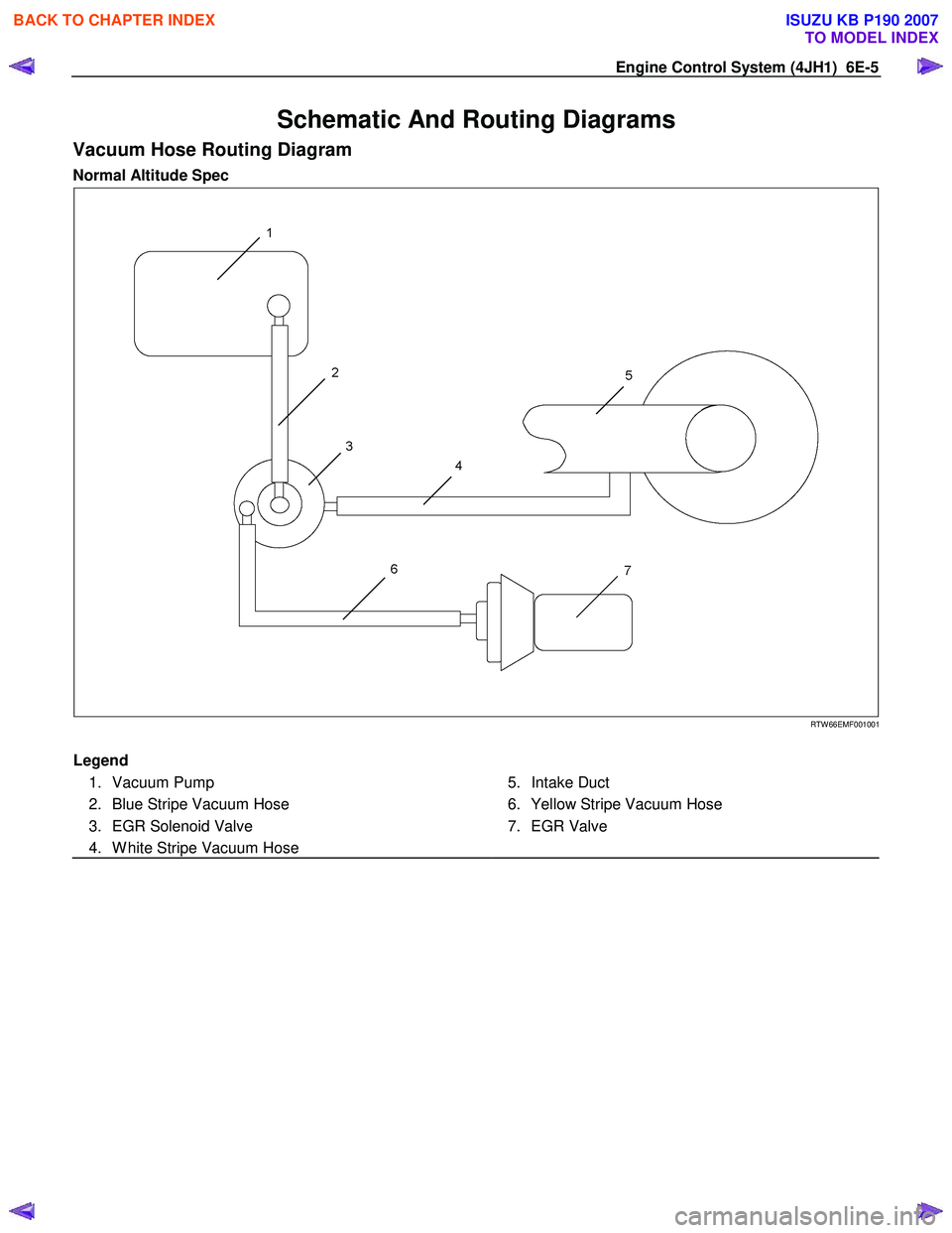
Vacuum Hose Routing Diagram
Normal Altitude Spec
RTW 66EMF001001
Legend
1. Vacuum Pump
2. Blue Stripe Vacuum Hose
3. EGR Solenoid Valve
4. W hite Stripe Vacuum Hose
5. Intake Duct
6. Yellow Stripe Vacuum Hose
7. EGR Valve
BACK TO CHAPTER INDEX
TO MODEL INDEX
ISUZU KB P190 2007
Page 1334 of 6020
SECTION 6F
EXHAUST SYSTEM
TABLE OF CONTENTS
PAGE
Main Data and Specifications ........................................................................................... 6F - 2
General Description .......................................................................................................... 6 F - 3
Removal and Installation .................................................................................................. 6F - 4
Inspection and Repair ....................................................................................................... 6F - 6
General Description .......................................................................................................... 6 F -7
EGR System Diagram........................................................................................................ 6F 9
Inspection ..................................................................................................................... ..... 6F-11
EGR Cooler (4JA1TC/4JH1TC Euro-III model)................................................................. 6F-12
Turbocharger ................................................................................................................... .. 6F -15
Main Data and Specifications....................................................................................... 6F -15
General Description .......................................................................................................... 6 F -16
Inspection and Repair ....................................................................................................... 6F -17
Special Tools .................................................................................................................. ... 6F -19
IHI Service Network ........................................................................................................... 6F -20
EXH
AU ST SY STEM 6F – 1
BACK TO CHAPTER INDEX
TO MODEL INDEX
ISUZU KB P190 2007
Page 1342 of 6020
EXHAUST SYSTEM 6F – 9
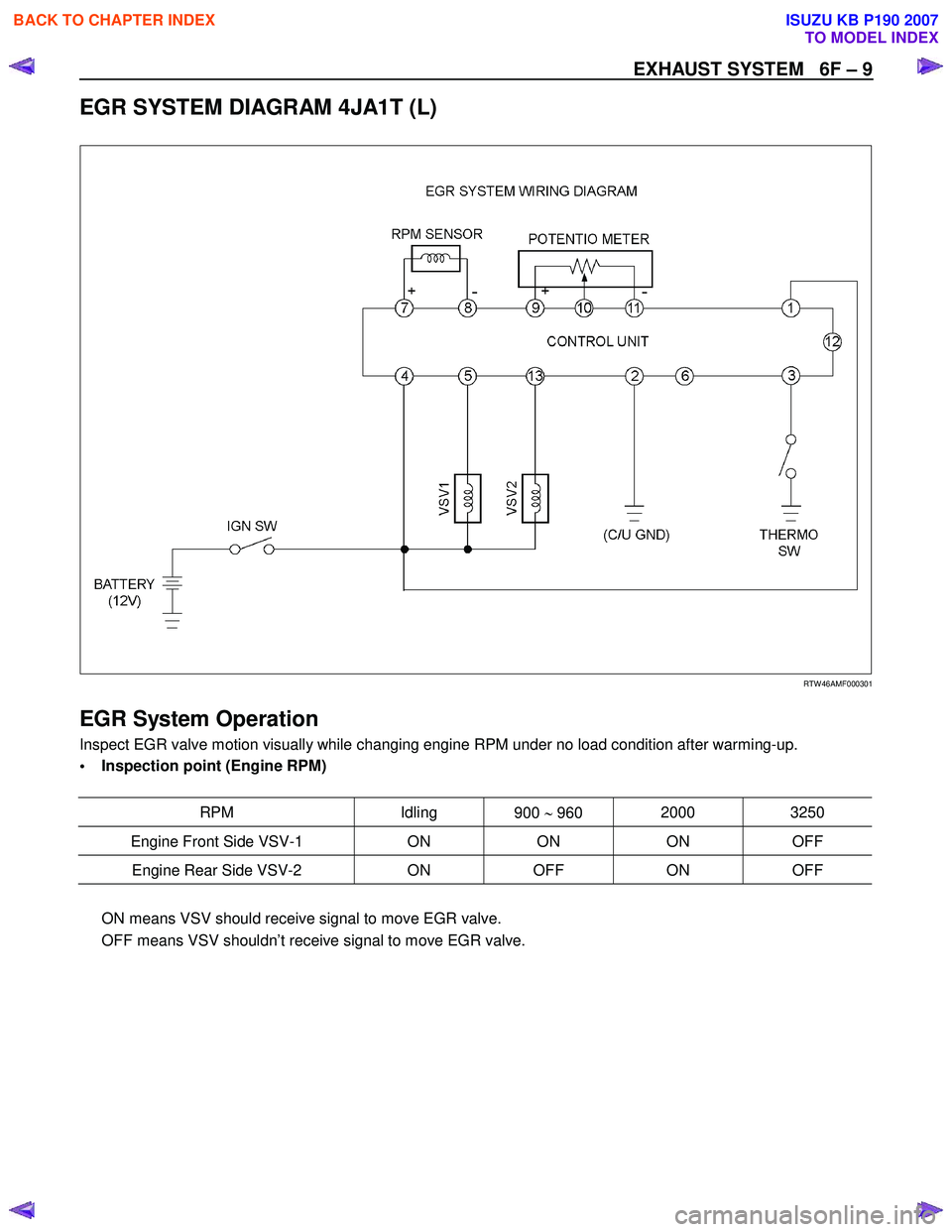
EGR SYSTEM DIAGRAM 4JA1T (L)
RTW 46AMF000301
EGR System Operation
Inspect EGR valve motion visually while changing engine RPM under no load condition after warming-up.
• Inspection point (Engine RPM)
RPM Idling 900 ∼ 960 2000 3250
Engine Front Side VSV-1
ON ON ON OFF
Engine Rear Side VSV-2 ON OFF ON OFF
ON means VSV should receive signal to move EGR valve.
OFF means VSV shouldn’t receive signal to move EGR valve.
BACK TO CHAPTER INDEX
TO MODEL INDEX
ISUZU KB P190 2007
Page 1500 of 6020
6A-140 ENGINE MECHANICAL (4JK1/4JJ1)
Lubrication System
Service Precautions
• During each disassembly, remove the old gasket
adhering to each part and mating part completel
y
using a scraper at the location, where the fluid
gasket is to be used, clean the traces of oil,
moisture, and dirt completely using waste cotton
and apply the specified new fluid gasket at each
location.
•
Avoid excessive or insufficient coating volume.
Note that seizure may occur in case of excessive
coating due to clogging of the oil gallery and oil jet,
and oil and water leakage may occur if the coating
is insufficient.
• Always, the start and end of the application should
be overlapped.
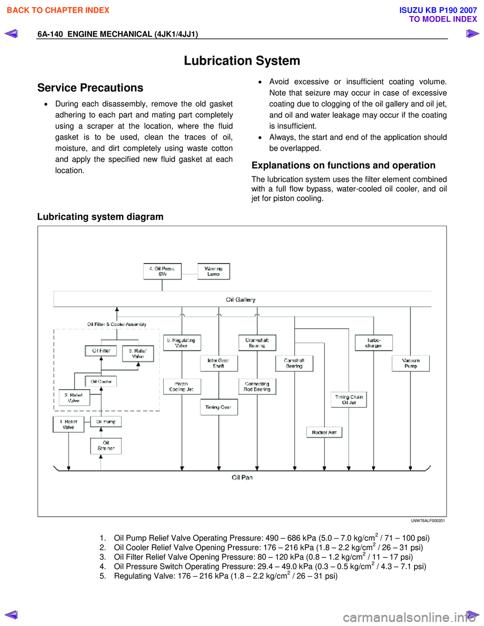
Explanations on functions and operation
The lubrication system uses the filter element combined
with a full flow bypass, water-cooled oil cooler, and oil
jet for piston cooling.
Lubricating system diagram
LNW 76ALF000201
1. Oil Pump Relief Valve Operating Pressure: 490 – 686 kPa (5.0 – 7.0 kg/cm2 / 71 – 100 psi)
2. Oil Cooler Relief Valve Opening Pressure: 176 – 216 kPa (1.8 – 2.2 kg/cm2 / 26 – 31 psi)
3. Oil Filter Relief Valve Opening Pressure: 80 – 120 kPa (0.8 – 1.2 kg/cm2 / 11 – 17 psi)
4. Oil Pressure Switch Operating Pressure: 29.4 – 49.0 kPa (0.3 – 0.5 kg/cm2 / 4.3 – 7.1 psi)
5. Regulating Valve: 176 – 216 kPa (1.8 – 2.2 kg/cm2 / 26 – 31 psi)
BACK TO CHAPTER INDEX
TO MODEL INDEX
ISUZU KB P190 2007
Page 1544 of 6020
FUEL SYSTEM (4JK1/4JJ1) 6C-3
Explanations on functions and operation
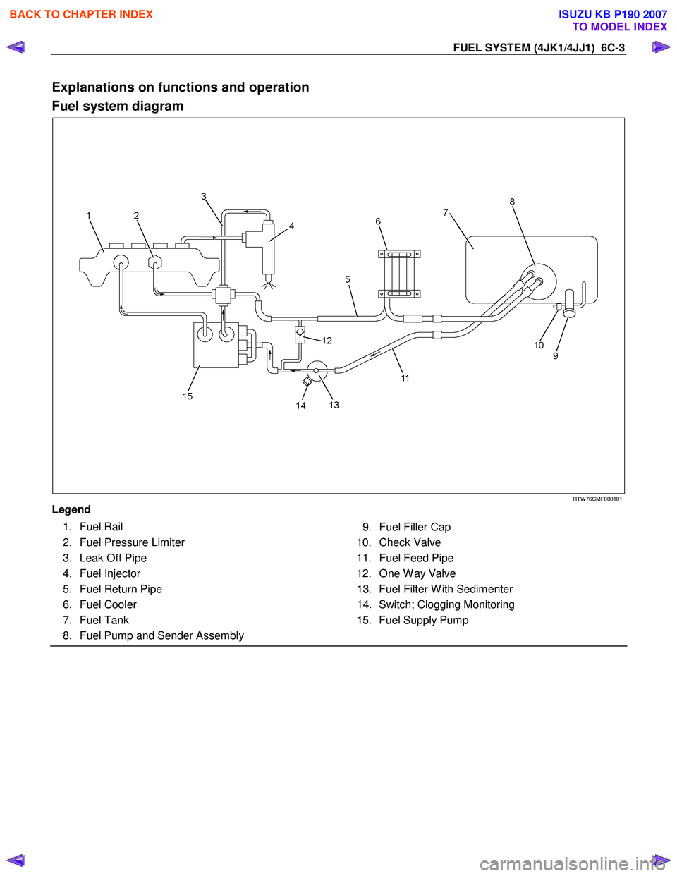
Fuel system diagram
RTW 76CMF000101
Legend
1. Fuel Rail
2. Fuel Pressure Limiter
3. Leak Off Pipe
4. Fuel Injector
5. Fuel Return Pipe
6. Fuel Cooler
7. Fuel Tank
8. Fuel Pump and Sender Assembly
9. Fuel Filler Cap
10. Check Valve
11. Fuel Feed Pipe
12. One W ay Valve 13. Fuel Filter W ith Sedimenter
14. Switch; Clogging Monitoring
15. Fuel Supply Pump
BACK TO CHAPTER INDEX
TO MODEL INDEX
ISUZU KB P190 2007
Page 1589 of 6020
ENGINE ELECTRICAL (4JK1/4JJ1) 6D-1
SECTION 6D
ENGINE ELECTRICAL
TABLE OF CONTENTS
Charging System ................................................ 6D-2
Servicing Cautions .......................................... 6D-2
Important Generator Components and
Function.......................................................... 6D-2
Troubleshooting .............................................. 6D-5
Diagnosis......................................................... 6D-7
Specifications .................................................. 6D-8
Unit Se rv ic ing (4 JJ 1) ....................................... .... ..6D -9
Disassembly .................................................... 6D-10
Inspection and Repair ..................................... 6D-11 Rotor Assembly ........................................... 6D-11
Stator Coil .................................................... 6D-12
Brushes ....................................................... 6D-12
Rectifier ....................................................... 6D-13
Regulator Assembly..................................... 6D-13
Measuring Procedure .................................. 6D-13
Reassembly..................................................... 6D-14
Final Assembly ................................................ 6D-14
Starter Motor ...................................................... 6D-15 Starting Circuit Diagram .................................. 6D-15
Removal and Installation ................................. 6D-15 Important Operations – Removal................. 6D-15
Important Operations – Installation.............. 6D-15
Disassembly .................................................... 6D-16 Disassembly Steps ...................................... 6D-16
Important Operations ................................... 6D-17
Inspection and Repair ..................................... 6D-20 Armature ...................................................... 6D-20
Yoke............................................................. 6D-21
Brush and Brush Holder .............................. 6D-22
Overrunning Clutch...................................... 6D-22
Bearing ........................................................ 6D-23
Reassembly..................................................... 6D-24 Reassembly Steps ....................................... 6D-24
Important Operations ................................... 6D-25
Inspection After Assembly ........................... 6D-26
Magnetic Switch .............................................. 6D-27
Torque Specifications...................................... 6D-28
Pre-Heating System ........................................... 6D-29 Inspection and Repair ..................................... 6D-29 Visual Check................................................ 6D-29
Glow Relay .................................................. 6D-29
Glow Plug .................................................... 6D-29
BACK TO CHAPTER INDEX
TO MODEL INDEX
ISUZU KB P190 2007
Page 1603 of 6020

ENGINE ELECTRICAL (4JK1/4JJ1) 6D-15
Starter Motor
Starting Circuit Diagram
RTW 46DSH005501
Removal and Installation
Read this Section carefully before performing any
removal and installation procedure. This Section gives
you important points as well as the order of operation.
Be sure that you understand everything in this Section
before you begin.
Important Operations - Removal
Starter Motor
1. Disconnect the battery cable and the ground cable at the battery terminals.
2. Remove the A/T oil level gage.
3. Remove the Engine oil level gage.
4. Disconnect the magnetic switch cable at the terminal bolts.
5. Disconnect the battery cable at the starter moto
r
and the ground cable at the cylinder body.
6. Remove the starter motor from the engine.
Important Operations – Installation
Follow the removal procedure in the reverse order to
perform the installation procedure. Pay careful attention
to the important points during the installation procedure.
Starter Motor
1. Install the starter motor to the rear plate.
2. Tighten the starter motor bolts to the specified torque.
Starter Motor Bolt Torque N⋅m (kg ⋅m/lb ft)
85 (8.7 / 63)
3. Install the Engine oil level gage.
4. Install the A/T oil level gage.
5. Reconnect the battery cable at the starter moto
r
and the ground cable at the cylinder body.
6. Reconnect the battery cable and the ground cable at the battery terminals.
BACK TO CHAPTER INDEX
TO MODEL INDEX
ISUZU KB P190 2007
Page 1618 of 6020

ENGINE CONTROL SYSTEM (4JK1/4JJ1) 6E-1
SECTION 6E
ENGINE CONTROL SYSTEM(4JK1/4JJ1)
TABLE OF CONTENTS
Specifications . . . . . . . . . . . . . . . . . . . . . . . . . . . . 6E-3 Temperature vs Resistance . . . . . . . . . . . . . . . . 6E-3
Altitude vs Barometric Pressure . . . . . . . . . . . . . 6E-3
Diagnostic Trouble Code (DTC) Type Definitions . . . . . . . . . . . . . . . . . . . . . . . . . . . . . 6E-4
Diagnostic Trouble Code (DTC) List . . . . . . . . . 6E-4
Schematic and Rounting Diagrams. . . . . . . . . . . . 6E-9 Fuel System Routing Diagram . . . . . . . . . . . . . . 6E-9
Vacuum Hose Routing Diagram . . . . . . . . . . . . . 6E-9
Engine Controls Schematics . . . . . . . . . . . . . . 6E-10
Component Locator. . . . . . . . . . . . . . . . . . . . . . . 6E-27 Engine Controls Component Views . . . . . . . . . 6E-27
Engine Control Module (ECM) Connector End Views . . . . . . . . . . . . . . . . . . . . . . . . . . . . 6E-30
Engine Control Connector End Views . . . . . . . 6E-33
Diagnostic Information and Procedures . . . . . . . 6E-42 Engine Control System Check Sheet . . . . . . . . 6E-42
Diagnostic Starting Point - Engine Controls . . . 6E-43
Diagnostic System Check - Engine Controls . . 6E-44
Scan Tool Data List . . . . . . . . . . . . . . . . . . . . . 6E-46
Scan Tool Data Definitions . . . . . . . . . . . . . . . . 6E-49
Scan Tool Output Controls . . . . . . . . . . . . . . . . 6E-54
Scan Tool Does Not Power Up. . . . . . . . . . . . . 6E-55
Scan Tool Does Not Communicate with CAN Device. . . . . . . . . . . . . . . . . . . . . . . . . . . 6E-56
Lost Communication with The Engine Control Module (ECM) . . . . . . . . . . . . . . . . . . 6E-59
Engine Cranks but Does Not Run . . . . . . . . . . 6E-62
DTC P0016 (Flash Code 16) . . . . . . . . . . . . . . 6E-68
DTC P0045 (Flash Code 33) . . . . . . . . . . . . . . 6E-70
DTC P0087 (Flash Code 225) . . . . . . . . . . . . . 6E-72
DTC P0088 (Flash Code 118) . . . . . . . . . . . . . 6E-77
DTC P0089 (Flash Code 151) . . . . . . . . . . . . . 6E-82
DTC P0091 or P0092 (Flash Code 247) . . . . . 6E-85
DTC P0093 (Flash Code 227) . . . . . . . . . . . . . 6E-88
DTC P0101 (Flash Code 92) . . . . . . . . . . . . . . 6E-93
DTC P0102 or P0103 (Flash Code 91) . . . . . . 6E-96
DTC P0107 or P0108 (Flash Code 32) . . . . . 6E-100
DTC P0112 or P0113 (Flash Code 22) . . . . . 6E-104
DTC P0116 (Flash Code 23) . . . . . . . . . . . . . 6E-108
DTC P0117 or P0118 (Flash Code 23) . . . . . 6E-110
DTC P0122 or P0123 (Flash Code 43) . . . . . 6E-114
DTC P0182 or P0183 (Flash Code 211) . . . . 6E-118
DTC P0192 or P0193 (Flash Code 245) . . . . 6E-122
DTC P0201, P0202, P0203 or P0204 (Flash Code 271, 272, 273 or 274) . . . . . . . . 6E-126
DTC P0217 (Flash Code 542) . . . . . . . . . . . . 6E-133
DTC P0219 (Flash Code 543) . . . . . . . . . . . . 6E-135
DTC P0231 or P0232 (Flash Code 69) . . . . . 6E-137
DTC P0234 (Flash Code 42) . . . . . . . . . . . . . 6E-140 DTC P0299 (Flash Code 65) . . . . . . . . . . . . . 6E-143
DTC P0335 (Flash Code 15) . . . . . . . . . . . . . 6E-146
DTC P0336 (Flash Code 15) . . . . . . . . . . . . . 6E-149
DTC P0340 (Flash Code 14) . . . . . . . . . . . . . 6E-151
DTC P0341 (Flash Code 14) . . . . . . . . . . . . . 6E-154
DTC P0380 (Flash Code 66) . . . . . . . . . . . . . 6E-156
DTC P0401 (Flash Code 93) . . . . . . . . . . . . . 6E-159
DTC P0403 (Flash Code 37) . . . . . . . . . . . . . 6E-161
DTC P0404 (Flash Code 45) . . . . . . . . . . . . . 6E-164
DTC P0405 or P0406 (Flash Code 44) . . . . . 6E-166
DTC P0500 (Flash Code 25) . . . . . . . . . . . . . 6E-170
DTC P0501 (Flash Code 25) . . . . . . . . . . . . . 6E-174
DTC P0512 (Flash Code 417) . . . . . . . . . . . . 6E-176
DTC P0562 or P0563 (Flash Code 35) . . . . . 6E-178
DTC P0565 (Flash Code 515) . . . . . . . . . . . . 6E-181
DTC P0566 (Flash Code 516) . . . . . . . . . . . . 6E-183
DTC P0567 (Flash Code 517) . . . . . . . . . . . . 6E-185
DTC P0568 (Flash Code 518) . . . . . . . . . . . . 6E-187
DTC P0571 (Flash Code 26) . . . . . . . . . . . . . 6E-189
DTC P0601 (Flash Code 53) . . . . . . . . . . . . . 6E-192
DTC P0602 (Flash Code 154) . . . . . . . . . . . . 6E-193
DTC P0604 or P0606 (Flash Code 153 or 51) . . . . . . . . . . . . . . . . . 6E-195
DTC P0615 (Flash Code 19) . . . . . . . . . . . . . 6E-196
DTC P0633 (Flash Code 176) . . . . . . . . . . . . 6E-198
DTC P0638 (Flash Code 61) . . . . . . . . . . . . . 6E-199
DTC P0642 or P0643 (Flash Code 55) . . . . . 6E-201
DTC P0650 (Flash Code 77) . . . . . . . . . . . . . 6E-204
DTC P0652 or P0653 (Flash Code 56) . . . . . 6E-207
DTC P0661 or P0662 (Flash Code 58) . . . . . 6E-211
DTC P0698 or P0699 (Flash Code 57) . . . . . 6E-215
DTC P0700 (Flash Code 185) . . . . . . . . . . . . 6E-219
DTC P1064 or P1065 (Flash Code 247) . . . . 6E-220
DTC P1093 (Flash Code 227) . . . . . . . . . . . . 6E-224
DTC P1094 (Flash Code 226) . . . . . . . . . . . . 6E-229
DTC P1196, P1197 or P1198 (Flash Code 461) . . . . . . . . . . . . . . . . . . . . . 6E-235
DTC P124B (Flash Code 157) . . . . . . . . . . . . 6E-237
DTC P1261 (Flash Code 34) . . . . . . . . . . . . . 6E-240
DTC P1262 (Flash Code 34) . . . . . . . . . . . . . 6E-242
DTC P1404 (Flash Code 45) . . . . . . . . . . . . . 6E-244
DTC P1411, P1412 or P1413 (Flash Code 445) . . . . . . . . . . . . . . . . . . . . . 6E-246
DTC P156A or P156B (Flash Code 135) . . . . 6E-248
DTC P161B (Flash Code 179) . . . . . . . . . . . . 6E-251
DTC P1621 (Flash Code 54, 254) . . . . . . . . . 6E-253
DTC P1664 (Flash Code 76) . . . . . . . . . . . . . 6E-255
DTC P2100, P2101 or P2103 (Flash Code 446) . . . . . . . . . . . . . . . . . . . . . 6E-258
DTC P2122 or P2123 (Flash Code 121) . . . . 6E-261
BACK TO CHAPTER INDEX
TO MODEL INDEX
ISUZU KB P190 2007
Page 1626 of 6020
ENGINE CONTROL SYSTEM (4JK1/4JJ1) 6E-9
Schematic and Rounting Diagrams
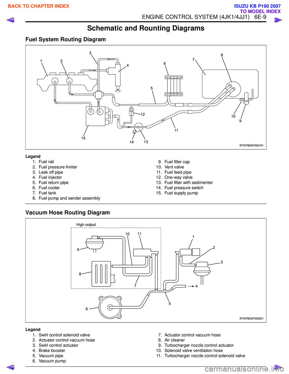
Fuel System Routing Diagram
Legend1. Fuel rail
2. Fuel pressure limiter
3. Leak off pipe
4. Fuel injector
5. Fuel return pipe
6. Fuel cooler
7. Fuel tank
8. Fuel pump and sender assembly 9. Fuel filler cap
10. Vent valve 11. Fuel feed pipe
12. One-way valve
13. Fuel filter with sedimenter
14. Fuel pressure switch
15. Fuel supply pump
Vacuum Hose Routing Diagram
Legend
1. Swirl control solenoid valve
2. Actuator control vacuum hose
3. Swirl control actuator
4. Brake booster
5. Vacuum pipe
6. Vacuum pump 7. Actuator control vacuum hose
8. Air cleaner
9. Turbocharger nozzle control actuator
10. Solenoid valve ventilation hose 11. Turbocharger nozzle control solenoid valve
RTW76ESF000101
12 3
4
5
117
8
9
10
14
13
12
15
6
RTW76ESF000201
1 2
4
5
6
9
8
3
7
11
High output10
BACK TO CHAPTER INDEX
TO MODEL INDEX
ISUZU KB P190 2007