diagram ISUZU KB P190 2007 Workshop Repair Manual
[x] Cancel search | Manufacturer: ISUZU, Model Year: 2007, Model line: KB P190, Model: ISUZU KB P190 2007Pages: 6020, PDF Size: 70.23 MB
Page 5852 of 6020

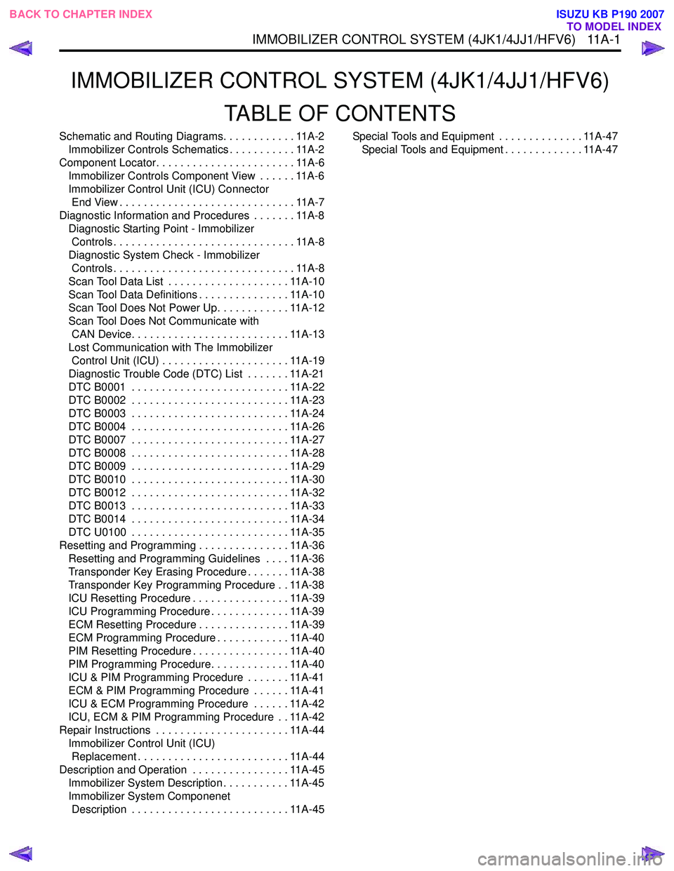
IMMOBILIZER CONTROL SYSTEM (4JK1/4JJ1/HFV6)TABLE OF CONTENTS
Schematic and Routing Diagrams. . . . . . . . . . . . 11A-2Immobilizer Controls Schematics . . . . . . . . . . . 11A-2
Component Locator. . . . . . . . . . . . . . . . . . . . . . . 11A-6 Immobilizer Controls Component View . . . . . . 11A-6
Immobilizer Control Unit (ICU) Connector End View . . . . . . . . . . . . . . . . . . . . . . . . . . . . . 11A-7
Diagnostic Information and Procedures . . . . . . . 11A-8 Diagnostic Starting Point - Immobilizer Controls . . . . . . . . . . . . . . . . . . . . . . . . . . . . . . 11A-8
Diagnostic System Check - Immobilizer Controls . . . . . . . . . . . . . . . . . . . . . . . . . . . . . . 11A-8
Scan Tool Data List . . . . . . . . . . . . . . . . . . . . 11A-10
Scan Tool Data Definitions . . . . . . . . . . . . . . . 11A-10
Scan Tool Does Not Power Up. . . . . . . . . . . . 11A-12
Scan Tool Does Not Communicate with CAN Device. . . . . . . . . . . . . . . . . . . . . . . . . . 11A-13
Lost Communication with The Immobilizer Control Unit (ICU) . . . . . . . . . . . . . . . . . . . . . 11A-19
Diagnostic Trouble Code (DTC) List . . . . . . . 11A-21
DTC B0001 . . . . . . . . . . . . . . . . . . . . . . . . . . 11A-22
DTC B0002 . . . . . . . . . . . . . . . . . . . . . . . . . . 11A-23
DTC B0003 . . . . . . . . . . . . . . . . . . . . . . . . . . 11A-24
DTC B0004 . . . . . . . . . . . . . . . . . . . . . . . . . . 11A-26
DTC B0007 . . . . . . . . . . . . . . . . . . . . . . . . . . 11A-27
DTC B0008 . . . . . . . . . . . . . . . . . . . . . . . . . . 11A-28
DTC B0009 . . . . . . . . . . . . . . . . . . . . . . . . . . 11A-29
DTC B0010 . . . . . . . . . . . . . . . . . . . . . . . . . . 11A-30
DTC B0012 . . . . . . . . . . . . . . . . . . . . . . . . . . 11A-32
DTC B0013 . . . . . . . . . . . . . . . . . . . . . . . . . . 11A-33
DTC B0014 . . . . . . . . . . . . . . . . . . . . . . . . . . 11A-34
DTC U0100 . . . . . . . . . . . . . . . . . . . . . . . . . . 11A-35
Resetting and Programming . . . . . . . . . . . . . . . 11A-36 Resetting and Programming Guidelines . . . . 11A-36
Transponder Key Erasing Procedure . . . . . . . 11A-38
Transponder Key Programming Procedure . . 11A-38
ICU Resetting Procedure . . . . . . . . . . . . . . . . 11A-39
ICU Programming Procedure . . . . . . . . . . . . . 11A-39
ECM Resetting Procedure . . . . . . . . . . . . . . . 11A-39
ECM Programming Procedure . . . . . . . . . . . . 11A-40
PIM Resetting Procedure . . . . . . . . . . . . . . . . 11A-40
PIM Programming Procedure. . . . . . . . . . . . . 11A-40
ICU & PIM Programming Procedure . . . . . . . 11A-41
ECM & PIM Programming Procedure . . . . . . 11A-41
ICU & ECM Programming Procedure . . . . . . 11A-42
ICU, ECM & PIM Programming Procedure . . 11A-42
Repair Instructions . . . . . . . . . . . . . . . . . . . . . . 11A-44 Immobilizer Control Unit (ICU) Replacement . . . . . . . . . . . . . . . . . . . . . . . . . 11A-44
Description and Operation . . . . . . . . . . . . . . . . 11A-45 Immobilizer System Description . . . . . . . . . . . 11A-45
Immobilizer System Componenet Description . . . . . . . . . . . . . . . . . . . . . . . . . . 11A-45 Special Tools and Equipment . . . . . . . . . . . . . . 11A-47
Special Tools and Equipment . . . . . . . . . . . . . 11A-47
IM MOBI LIZER CONTR OL SY STEM (4JK 1/4 JJ1/ HFV 6) 1 1A- 1
BACK TO CHAPTER INDEX
TO MODEL INDEX
ISUZU KB P190 2007
Page 5853 of 6020

11A-2 IMMOBILIZER CONTROL SYSTEM (4JK1/4JJ1/HFV6)
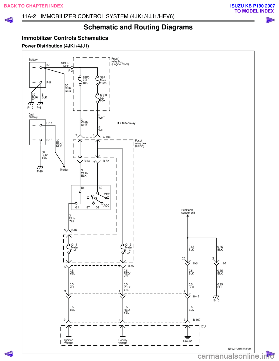
Schematic and Routing Diagrams
Immobilizer Controls Schematics
Power Distribution (4JK1/4JJ1)
BACK TO CHAPTER INDEXTO MODEL INDEX
ISUZU KB P190 2007
Page 5899 of 6020

IMMOBILIZER SYSTEM (C24SE, 4JA1-T) 11A-1
IMMOBILIZER SYSTEM
(C24SE, 4JA1-T)
CONTENTS
Service Precaution .................................................. 11A-2
General Description ................................................ 11A-3
W hat happens without proper transponder
operation? ........................................................... 11A-5
No proper transponder is available, what
should be done for the system? ...................... 11A-5
Caution to the operation ..................................... 11A-5
Summary of operation ......................................... 11A-5
W hat your organization should provide for
your customer .................................................... 11A-5
Car Pass .............................................................. 11A-5
Security code management .............................. 11A-5
Essential tool (Scan tool : Tech-2) .................. 11A-5
Circuit Diagram .................................................. 11A-6
Parts Location .......................................................... 11A-8
Immobilizer control unit (ICU); For Electronic
Control Engine (C24SE) .................................... 11A-9
Pin-outs; For Electronic Control Engine
(C24SE) ............................................................... 11A-10
Immobilizer control unit (ICU); Mechanical
Control Engine (4JA1-T) ...................................11A-11
Immobilizer coil (Antenna) ....................................11A-13
Transponder (Key) ............................................11A-13
Check engine lamp ...........................................11A-13
Engine control module (ECM) ...........................11A-13
Car Pass Card ...................................................11A-14 Loss of car pass card .......................................... 11A-14
Instructions on Filling Out the form "Data
request, car pass" ............................................. 11A-14
Important Instructions ........................................ 11A-15
lmportant information on Programming ..............11A-17
Security code ....................................................... 11A-17
Entering a code ................................................... 11A-17
Transponder (Key) ............................................. 11A-17
Tech-2 Scan Tool .................................................. 11A-18
Operating Procedure .......................................... 11A-18
Menu .................................................................... 11A-19
DTC ...................................................................... 11A-19
Clear DTC Information ......................................11A-19
Tech-2 Data Display .......................................... 11A-19
Check Vehicle Identification Number (VIN) ....11A-19
Reset Immobilizer (Reset Immobilizer
Control Unit) ....................................................... 11A-19
Reset Engine Control Module (Reset ECM) ..11A-20
Erase transponder key ......................................11A-20
Programming Immobilizer Function ................11A-21
Programming ICU .............................................. 11A-22
Programming ECM ............................................ 11A-23
Programming ICU and ECM .............................11A-24
Transponder program ........................................ 11A-24
Data List .............................................................. 11A-26
Diagnostic procedure ............................................ 11A-27
Clearing Diagnostic Trouble Codes ....................11A-27
Verifying Vehicle Repair .......................................11A-27
Diagnostic Aids ...................................................... 11A-27
Check the condition for system parts ..............11A-27
Check the Electro-Magnetic Interference
(EMI) ................................................................... 11A-27
Check the other items .......................................11A-27
Check the operation ........................................... 11A-27
Diagnostic Trouble Code (DTC) list ....................11A-28
IMMOBILIZER SYSTEM CHECK .......................11A-30
NO IMMOBILIZER W ARNING LAMP ................11A-32
CHECK IMMOBILIZER W ARNING LAMP O
STEADY ................................................................ 11A-33
B0001 REPLACE ELECTRONIC CONTROL
UNIT (ECU) (IMMOBILIZER FAULT) ................11A-34
B0002 IMMOBILIZER NOT PROGRAMMED ...11A-35
B0003 TRANSPONDER KEY PROBLEM .........11A-36
B0004 IMMOBILIZER COIL CIRCUIT
(ANTENNA COIL FAULT) ...................................11A-38
B0005 COMMUNICATION LINE W VOLTAGE
LOW ....................................................................... 11A-39
B0006 COMMUNICATION LINE W VOLTAGE
HIGH ...................................................................... 11A-40
BACK TO CHAPTER INDEX
TO MODEL INDEX
ISUZU KB P190 2007
Page 5904 of 6020

11A-6 IMMOBILIZER SYSTEM (C24SE, 4JA1-T)
Circuit Diagram
•
••
•
Gasoline Engine (C24SE)
RTW 7BALF000101
BACK TO CHAPTER INDEX TO MODEL INDEX
ISUZU KB P190 2007
Page 5955 of 6020

ANTITHEFT SYSTEM 11B-1
SECTION 11B
ANTITHEFT SYSTEM
TABLE OF CONTENTS
Service Precaution .................................................. 11B- 2
General Description ................................................ 11B- 2
Diagrams And Schematics ................................. 11B- 5 System W iring Diagrams ................................ 11B- 5
Parts Location ................................................. 11B- 6
Circuit Diagram ..............................................11B-10
Antitheft control unit (A) ...................................11B-24
Pin-outs ...........................................................11B-24
Pin-Assignment ...............................................11B-25
lmportant information on Programming..............11B-26
Tech-2 Scan Tool ...............................................11B-27 Operating Procedure .......................................11B-27
Menu ...............................................................11B-28
DTC .................................................................11B-28
Clear DTC Information ....................................11B-28
Tech-2 Data Display........................................11B-28
Actuator Test ...................................................11B-28
Programming...................................................11B-30
Tech-2 Data List ..............................................11B-35
Diagnosis............................................................11B-36 Diagnostic procedure ......................................11B-36
Clearing Diagnostic Trouble Codes ................11B-36
Verifying Vehicle Repair ..................................11B-36
Diagnostic Aids................................................11B-36
Diagnostic Trouble Code (DTC) list
For Antitheft.....................................................11B-37
Antitheft System Check ...................................11B-38
No Antitheft Lamp ...........................................11B-39
DTC13 Security code not yet programmed .....11B-40
DTC14 No remote key programmed ...............11B-41
DTC16 Door lock actuators short circuit
to ground .........................................................11B-42
DTC20 Broken wire to door lock actuators .....11B-43
DTC21 Remote key 1 with random code
out of capture range ........................................11B-44
DTC22 Remote key 2 with random code
out of capture range ........................................11B-45
DTC23 Remote key 3 with random code
out of capture range ........................................11B-46
DTC24 Remote key 4 with random code
out of capture range ........................................ 11B-47
DTC25 Remote key 5 with random code
out of capture range ........................................ 11B-48
DTC28 Input immobilizer short circuit
to ground ......................................................... 11B-49
DTC29 Broken wire to immobilizer ................. 11B-50
DTC31 Actuator driver door defect ................. 11B-51
DTC32 Actuator passenger door defect ......... 11B-52
DTC36 Broken wire to driver door................... 11B-53
DTC37 Broken wire to passenger door........... 11B-54
DTC41 Driver door Lock switch unlock
defect .............................................................. 11B-55
DTC42 Driver door Lock switch lock defect .... 11B-56
DTC43 Driver door Lock switch Super lock
defect .............................................................. 11B-57
DTC44 Passenger door Lock switch lock
defect .............................................................. 11B-58
DTC45 Passenger door Lock switch unlock
defect .............................................................. 11B-59
DTC47 Battery voltage for door lock actuators
is missing ........................................................ 11B-60
DTC50 A/D converter defect or battery
voltage less than 9 volt.................................... 11B-61
DTC51 EEPROM defect ................................. 11B-62
DTC52 EEPROM not programmed
by ISUZU ......................................................... 11B-63
DTC55 Control unit defect............................... 11B-64
DTC123 Output flasher short circuit to ground
or broken wire ................................................. 11B-65
DTC125 Output alarm horn broken wire ......... 11B-66
BACK TO CHAPTER INDEX TO MODEL INDEX
ISUZU KB P190 2007
Page 5959 of 6020

ANTITHEFT SYSTEM 11B-5
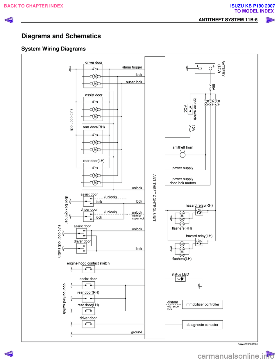
Diagrams and Schematics
System Wiring Diagrams
RAW 4C0XF000101
BACK TO CHAPTER INDEXTO MODEL INDEX
ISUZU KB P190 2007
Page 5964 of 6020

11B-10 ANTITHEFT SYSTEM
Circuit Diagram
4JJ1-TC, 4JK1-TC (except South Africa) (RHD)
RTW 78AXF033901
BACK TO CHAPTER INDEX
TO MODEL INDEX
ISUZU KB P190 2007