dimensions ISUZU KB P190 2007 Workshop User Guide
[x] Cancel search | Manufacturer: ISUZU, Model Year: 2007, Model line: KB P190, Model: ISUZU KB P190 2007Pages: 6020, PDF Size: 70.23 MB
Page 2099 of 6020
ENGINE MECHANICAL (C24SE) 6A-85
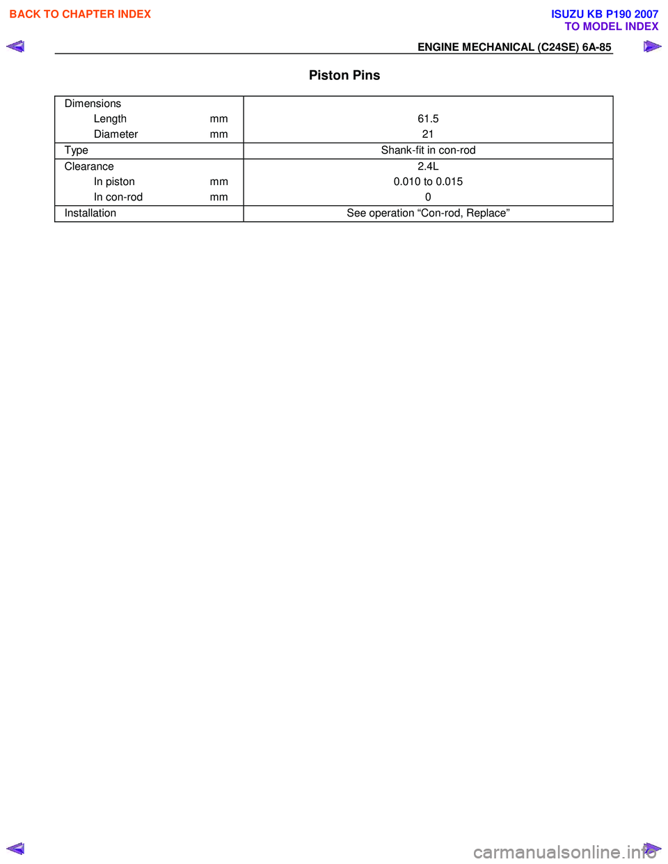
Piston Pins
Dimensions
Length mm
Diameter mm
61.5 21
Type Shank-fit in con-rod
Clearance
In piston mm
In con-rod mm 2.4L
0.010 to 0.015 0
Installation See operation “Con-rod, Replace”
BACK TO CHAPTER INDEX
TO MODEL INDEX
ISUZU KB P190 2007
Page 2100 of 6020
6A-86 ENGINE MECHANICAL (C24SE)
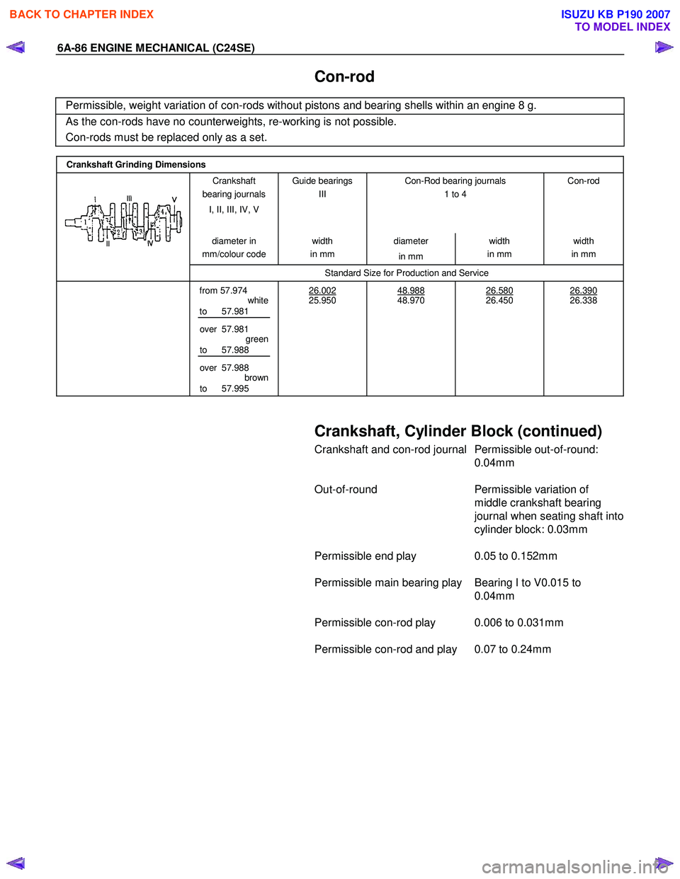
Con-rod
Permissible, weight variation of con-rods without pistons and bearing shells within an engine 8 g.
As the con-rods have no counterweights, re-working is not possible.
Con-rods must be replaced only as a set.
Crankshaft Grinding Dimensions
Crankshaft
bearing journals
I, II, III, IV, V Guide bearings
III
Con-Rod bearing journals
1 to 4
Con-rod
diameter
in
mm/colour code width
in mm diameter
in mm width
in mm width
in mm
Standard Size for Production and Service
from 57.974
white
to 57.981
over 57.981 green
to 57.988
over 57.988 brown
to 57.995 26.002
25.950
48.988
48.970
26.580
26.450
26.390
26.338
Crankshaft, Cylinder Block (continued)
Crankshaft and con-rod journal Permissible out-of-round:
0.04mm
Out-of-round Permissible variation of
middle crankshaft bearing
journal when seating shaft into
cylinder block: 0.03mm
Permissible end play 0.05 to 0.152mm
Permissible main bearing play Bearing I to V0.015 to 0.04mm
Permissible con-rod play 0.006 to 0.031mm
Permissible con-rod and play 0.07 to 0.24mm
BACK TO CHAPTER INDEX
TO MODEL INDEX
ISUZU KB P190 2007
Page 2446 of 6020

6E–276 ENGINE DRIVEABILITY AND EMISSIONS
• Oil in the combustion chamber.
• The spark plug gap is not set correctly.
If spark plug fouling is excessive, check the fuel and al
system for possible causes of trouble. If fuel and al
system are normal, install spark plugs of a higher heat
range which have the same physical dimensions as the
original equipment spark plugs.
The following symptoms are characteristics of spark
plugs that are running too hot:
• Fuel mixture is too lean.
• Heat range is incorrect.
If vehicle usage does not conform to normal driving
conditions, a more suitable spark plug may be
substituted.
If fuel and al system are normal, in most cases of this
sort, the problem can be corrected by using a colder
type spark plug with the same physical dimensions as
the original equipment spark plug.
3. Check the gaskets for damage and replace if necessary.
4. Measure the spark plug gap. The specification is 1.0 to 1.1mm (0.039 to 0.043").
5. Adjust the spark gap by bending the grounded electrode. Installation
1. Tighten the spark plug to the 25N·m (2.5kgf·m).
2. Push the spark plug cable in until it snaps in.
Installation Procedure 1. Install the spark plug to the cylinder head.
2. Tighten the spark plug with specified tightening torque.
Tightening Torque
• Bolt: 25N·m (2.5kgf·m) 3. Connect the spark plug cable to the spark plug.
4. Connect the negative battery cable.
NOTE: Verify any DTCs (diagnosis Trouble Code) are
not stored after replacement.
Verify proper connection of spark plug cables for each
cylinders.
BACK TO CHAPTER INDEX
TO MODEL INDEX
ISUZU KB P190 2007
Page 2693 of 6020

Engine Mechanical – V6 Page 6A1–214
3 Using an inside micrometer, measure the piston pin
bore (1). Compare the result with the piston pin
diameter and piston pin to piston pin bore clearance
listed in the specifications, refer to 5 Specifications.
4 If the clearance is excessive, determine which piece is out of specification and replace as required.
5 Replace the piston if any of its dimensions are out of specification.
6 If the new piston does not meet clearance specifications, the cylinder block may need to be
oversized to 0.25 mm. There is only one size of
oversized pistons and rings available for service.
Figure 6A1 – 387
Piston Ring Measurement
1 Measure the piston ring end gap using the following procedure:
a Place the piston ring (1) in the area of the bore where the piston ring will travel, approximately 25 mm below
the deck surface. Ensure the ring is square with the
cylinder bore by positioning the ring with the piston
head.
b Measure the end gap of the piston ring with feeler gauges (2), refer to 5 Specifications.
c If the clearance exceeds the provided specifications, the piston rings must be replaced.
d Repeat the procedure for all piston rings.
Figure 6A1 – 388
2 Measure the piston ring side clearance using the following procedure:
a Roll the piston ring (1) entirely around the piston ring groove. If any binding is caused by the ring groove,
dress the groove with a fine file. If any binding is
caused by a distorted piston ring, replace the ring.
b W ith the piston ring on the piston, use feeler gauges (2) to check clearance at multiple locations.
c Compare the measurements with piston ring side clearance listed in the specifications, refer to 5
Specifications.
d If the clearance is greater than specifications, replace the piston rings.
Figure 6A1 – 389
BACK TO CHAPTER INDEX
TO MODEL INDEX
ISUZU KB P190 2007
Page 2718 of 6020
Engine Mechanical – V6 Page 6A1–239
Inspect
Visual Inspection
NOTE
The following procedure assumes the engine has
been disassembled and cleaned, as described
above.
1 Inspect the crankshaft bearing journals for damage or spun bearings. The crankshaft bearing journals are not repairable and if damage is found, the cylinder block assembly must be replaced.
2 Inspect the primary camshaft chain tensioner mounting surface on the engine block for burrs or any defects that would affect the sealing of the new primary camshaft chain tensioner gasket.
3 Inspect all sealing and mating surfaces for damage, repair or replace the cylinder block assembly if required.
4 Inspect all threaded and through holes for damage or excessive debris.
5 Inspect all bolts for damage, if damaged replace with new bolts only.
6 Inspect the cylinder walls for cracks or damage. The cylinder sleeves are not serviced separately, if the cylinders are damaged the cylinder block assembly must be replaced.
7 Inspect the engine block for cracks. Do not repair any cracks. If cracks are found, the cylinder block assembly must be replaced. Repair any damaged threaded holes, refer to 4.9 Thread Repair Specifications.
Measuring Cylinder Bore Diameter
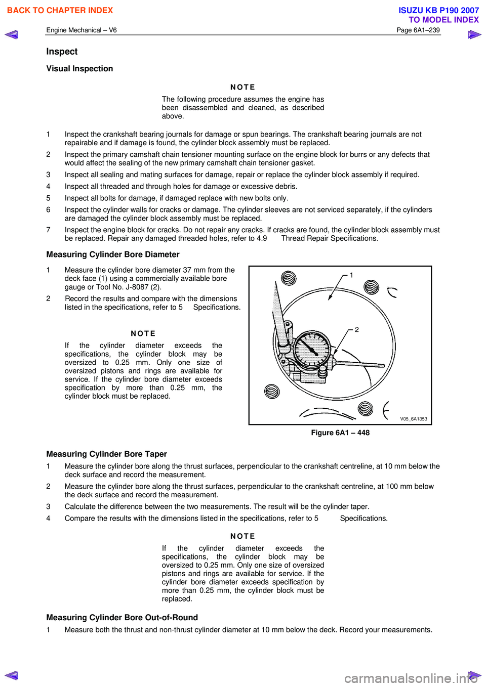
1 Measure the cylinder bore diameter 37 mm from the deck face (1) using a commercially available bore
gauge or Tool No. J-8087 (2).
2 Record the results and compare with the dimensions listed in the specifications, refer to 5 Specifications.
NOTE
If the cylinder diameter exceeds the
specifications, the cylinder block may be
oversized to 0.25 mm. Only one size of
oversized pistons and rings are available for
service. If the cylinder bore diameter exceeds
specification by more than 0.25 mm, the
cylinder block must be replaced.
Figure 6A1 – 448
Measuring Cylinder Bore Taper
1 Measure the cylinder bore along the thrust surfaces, perpendicular to the crankshaft centreline, at 10 mm below the deck surface and record the measurement.
2 Measure the cylinder bore along the thrust surfaces, perpendicular to the crankshaft centreline, at 100 mm below the deck surface and record the measurement.
3 Calculate the difference between the two measurements. The result will be the cylinder taper.
4 Compare the results with the dimensions listed in the specifications, refer to 5 Specifications.
NOTE
If the cylinder diameter exceeds the
specifications, the cylinder block may be
oversized to 0.25 mm. Only one size of oversized
pistons and rings are available for service. If the
cylinder bore diameter exceeds specification by
more than 0.25 mm, the cylinder block must be
replaced.
Measuring Cylinder Bore Out-of-Round
1 Measure both the thrust and non-thrust cylinder diameter at 10 mm below the deck. Record your measurements.
BACK TO CHAPTER INDEX
TO MODEL INDEX
ISUZU KB P190 2007
Page 2719 of 6020
Engine Mechanical – V6 Page 6A1–240
2 Calculate the difference between the two measurements. The result will indicate out-of-round at the upper end of
the cylinder.
3 Measure both the thrust and non-thrust cylinder diameter at 100 mm below the deck surface. Record your measurements.
4 Calculate the difference between the two measurements. The result will indicate out-of-round at the lower end of the cylinder.
5 Compare your results with the dimensions listed in the specifications, refer to 5 Specifications.
NOTE
If the cylinder diameter exceeds the
specifications, the cylinder block may be
oversized to 0.25 mm. Only one size of oversized
pistons and rings are available for service. If the
cylinder bore diameter exceeds specification by
more than 0.25 mm, the cylinder block must be
replaced.
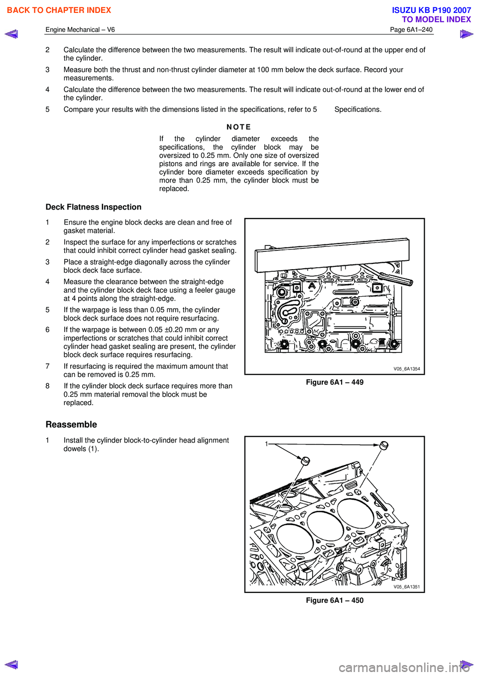
Deck Flatness Inspection
1 Ensure the engine block decks are clean and free of gasket material.
2 Inspect the surface for any imperfections or scratches that could inhibit correct cylinder head gasket sealing.
3 Place a straight-edge diagonally across the cylinder block deck face surface.
4 Measure the clearance between the straight-edge and the cylinder block deck face using a feeler gauge
at 4 points along the straight-edge.
5 If the warpage is less than 0.05 mm, the cylinder block deck surface does not require resurfacing.
6 If the warpage is between 0.05 ±0.20 mm or any imperfections or scratches that could inhibit correct
cylinder head gasket sealing are present, the cylinder
block deck surface requires resurfacing.
7 If resurfacing is required the maximum amount that can be removed is 0.25 mm.
8 If the cylinder block deck surface requires more than 0.25 mm material removal the block must be
replaced.
Figure 6A1 – 449
Reassemble
1 Install the cylinder block-to-cylinder head alignment
dowels (1).
Figure 6A1 – 450
BACK TO CHAPTER INDEX
TO MODEL INDEX
ISUZU KB P190 2007
Page 3047 of 6020
Engine Mechanical – V6 Page 6A1–270
Page 6A1–270
Piston Measurement
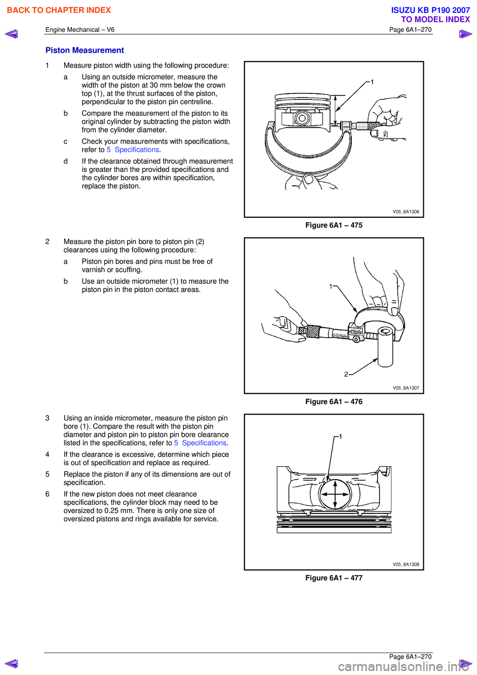
1 Measure piston width using the following procedure:
a Using an outside micr ometer, measure the
width of the piston at 30 mm below the crown
top (1), at the thrust surfaces of the piston,
perpendicular to the piston pin centreline.
b Compare the measurement of the piston to its
original cylinder by subtracting the piston width
from the cylinder diameter.
c Check your measurements with specifications, refer to 5 Specifications .
d If the clearance obtai ned through measurement
is greater than the prov ided specifications and
the cylinder bores are wi thin specification,
replace the piston.
Figure 6A1 – 475
2 Measure the piston pin bore to piston pin (2) clearances using the following procedure:
a Piston pin bores and pins must be free of varnish or scuffing.
b Use an outside micrometer (1) to measure the
piston pin in the piston contact areas.
Figure 6A1 – 476
3 Using an inside micrometer , measure the piston pin
bore (1). Compare the resu lt with the piston pin
diameter and piston pin to piston pin bore clearance
listed in the specifications, refer to 5 Specifications.
4 If the clearance is excessive, determine which piece is out of specification and replace as required.
5 Replace the piston if any of its dimensions are out of
specification.
6 If the new piston does not meet clearance specifications, the cylinder block may need to be
oversized to 0.25 mm. There is only one size of
oversized pistons and rings available for service.
Figure 6A1 – 477
BACK TO CHAPTER INDEX
TO MODEL INDEX
ISUZU KB P190 2007
Page 3074 of 6020
Engine Mechanical – V6 Page 6A1–297
Page 6A1–297
Clean
1 Remove all thread sealant, gasket material or sealant using a commercially available plastic or wood scraper.
2 Clean all the following areas with a suitable solvent:
• sealing surfaces,
• cooling passages,
• oil passages, and
• bearing journals.
3 Clean all threaded and through holes with a suitable solvent.
Safety glasses must be worn when using
compressed air.
4 Dry the engine block with compressed air.
Inspect
Visual Inspection
NOTE
The following procedure assumes the engine has
been disassembled and cleaned, as described
above.
1 Inspect the crankshaft bearing journals for damage or spun bearings. The crankshaft bearing journals are not
repairable and if damage is f ound, the cylinder block assembly must be replaced.
2 Inspect the primary camshaft chain t ensioner mounting surface on the engine block for burrs or any defects that
would affect the sealing of the new primary camshaft chain tensioner gasket.
3 Inspect all sealing and mating surfaces for damage, repair or replace the cylinder block assembly if required.
4 Inspect all threaded and through holes for damage or excessive debris.
5 Inspect all bolts for damage, if damaged replace with new bolts only.
6 Inspect the cylinder walls for cracks or damage. The cyli nder sleeves are not serviced separately, if the cylinders
are damaged the cylinder block assembly must be replaced.
7 Inspect the engine block for cracks. Do not repair any cra cks. If cracks are found, the cylinder block assembly must
be replaced. Repair any damaged threaded holes, refer to 4.9 Thread Repair Specifications.
Measuring Cylinder Bore Diameter
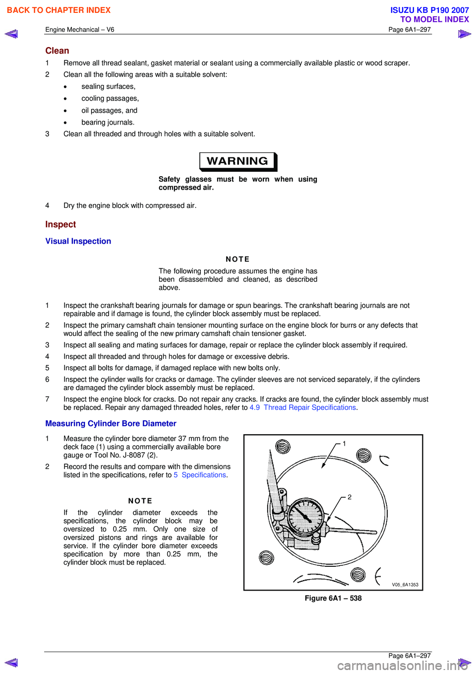
1 Measure the cylinder bore diameter 37 mm from the
deck face (1) using a commercially available bore
gauge or Tool No. J-8087 (2).
2 Record the results and compare with the dimensions listed in the specifications, refer to 5 Specifications.
NOTE
If the cylinder diameter exceeds the
specifications, the cylinder block may be
oversized to 0.25 mm. Only one size of
oversized pistons and rings are available for
service. If the cylinder bore diameter exceeds
specification by mo re than 0.25 mm, the
cylinder block must be replaced.
Figure 6A1 – 538
BACK TO CHAPTER INDEX
TO MODEL INDEX
ISUZU KB P190 2007
Page 3075 of 6020
Engine Mechanical – V6 Page 6A1–298
Page 6A1–298
Measuring Cylinder Bore Taper
1 Measure the cylinder bore along the thrust surfaces, perpendicular to the crankshaft centreline, at 10 mm below the
deck surface and record the measurement.
2 Measure the cylinder bore along the th rust surfaces, perpendicular to the crankshaft centreline, at 100 mm below
the deck surface and record the measurement.
3 Calculate the difference betw een the two measurements. The re sult will be the cylinder taper.
4 Compare the results with the dimensions listed in the specifications, refer to 5 Specifications.
NOTE
If the cylinder diameter exceeds the
specifications, the cylinder block may be
oversized to 0.25 mm. Only one size of oversized
pistons and rings are available for service. If the
cylinder bore diameter ex ceeds specification by
more than 0.25 mm, the cylinder block must be
replaced.
Measuring Cylinder Bore Out-of-Round
1 Measure both the thrust and non-thrust cylinder diameter at 10 mm below the deck. Record your measurements.
2 Calculate the difference bet ween the two measurements. The result will indicate out-of-r ound at the upper end of
the cylinder.
3 Measure both the thrust and non-thru st cylinder diameter at 100 mm below the deck surface. Record your
measurements.
4 Calculate the difference between the tw o measurements. The result will indicate out-of-round at the lower end of
the cylinder.
5 Compare your results with the dimensions listed in the specifications, refer to 5 Specifications.
NOTE
If the cylinder diameter exceeds the
specifications, the cylinder block may be
oversized to 0.25 mm. Only one size of oversized
pistons and rings are available for service. If the
cylinder bore diameter ex ceeds specification by
more than 0.25 mm, the cylinder block must be
replaced.
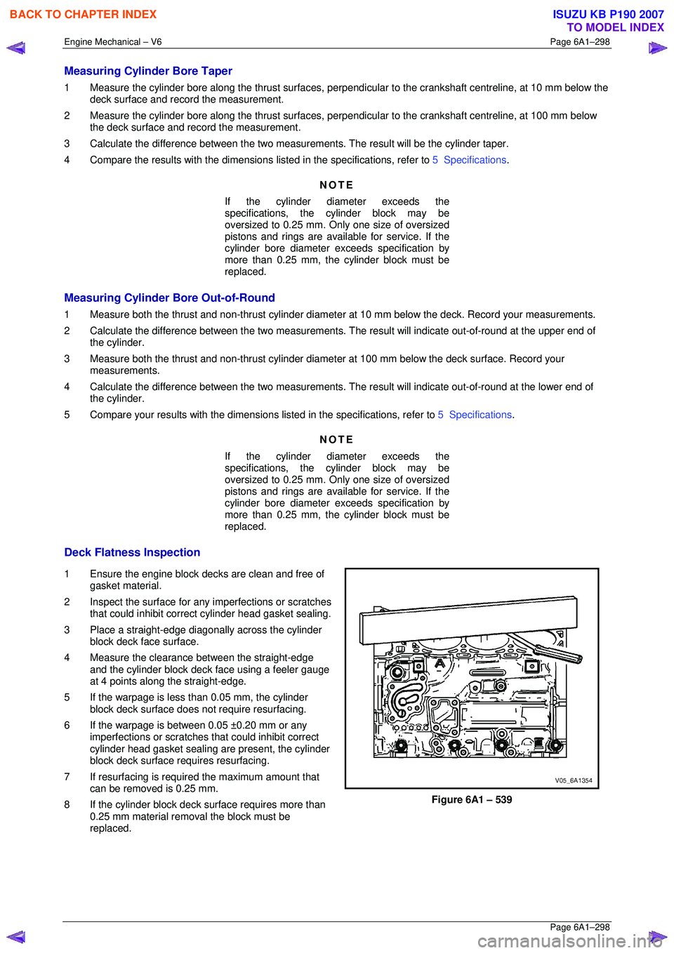
Deck Flatness Inspection
1 Ensure the engine block decks are clean and free of gasket material.
2 Inspect the surface for any imperfections or scratches
that could inhibit correct cylinder head gasket sealing.
3 Place a straight-edge diagonally across the cylinder block deck face surface.
4 Measure the clearance between the straight-edge
and the cylinder block deck face using a feeler gauge
at 4 points along the straight-edge.
5 If the warpage is less t han 0.05 mm, the cylinder
block deck surface does not require resurfacing.
6 If the warpage is between 0.05 ±0.20 mm or any imperfections or scratches that could inhibit correct
cylinder head gasket sealing are present, the cylinder
block deck surface requires resurfacing.
7 If resurfacing is requir ed the maximum amount that
can be removed is 0.25 mm.
8 If the cylinder block deck surface requires more than 0.25 mm material removal the block must be
replaced.
Figure 6A1 – 539
BACK TO CHAPTER INDEX
TO MODEL INDEX
ISUZU KB P190 2007
Page 3944 of 6020
Automatic Transmission – 4L60E – On-vehicle Servicing Page 7C4–31
Keep the control valve body level when
lowering it to prevent the loss of the
checkballs located in the body passages.
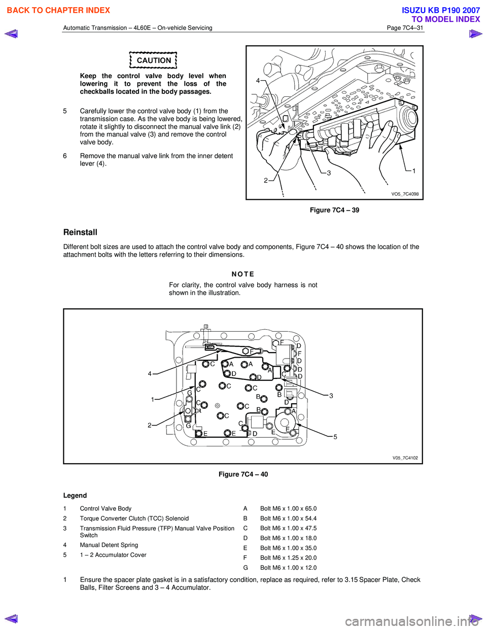
5 Carefully lower the control valve body (1) from the transmission case. As the valve body is being lowered,
rotate it slightly to disconnect the manual valve link (2)
from the manual valve (3) and remove the control
valve body.
6 Remove the manual valve link from the inner detent lever (4).
Figure 7C4 – 39
Reinstall
Different bolt sizes are used to attach the control valve body and components, Figure 7C4 – 40 shows the location of the
attachment bolts with the letters referring to their dimensions.
NOTE
For clarity, the control valve body harness is not
shown in the illustration.
Figure 7C4 – 40
Legend
1 Control Valve Body
2 Torque Converter Clutch (TCC) Solenoid
3 Transmission Fluid Pressure (TFP) Manual Valve Position Switch
4 Manual Detent Spring
5 1 – 2 Accumulator Cover A Bolt M6 x 1.00 x 65.0
B Bolt M6 x 1.00 x 54.4
C Bolt M6 x 1.00 x 47.5
D Bolt M6 x 1.00 x 18.0
E Bolt M6 x 1.00 x 35.0
F Bolt M6 x 1.25 x 20.0
G Bolt M6 x 1.00 x 12.0
1 Ensure the spacer plate gasket is in a satisfactory condition, replace as required, refer to 3.15 Spacer Plate, Check Balls, Filter Screens and 3 – 4 Accumulator.
BACK TO CHAPTER INDEX
TO MODEL INDEX
ISUZU KB P190 2007