ignition ISUZU KB P190 2007 Workshop User Guide
[x] Cancel search | Manufacturer: ISUZU, Model Year: 2007, Model line: KB P190, Model: ISUZU KB P190 2007Pages: 6020, PDF Size: 70.23 MB
Page 298 of 6020
POWER-ASSISTED STEERING SYSTEM 3B-37
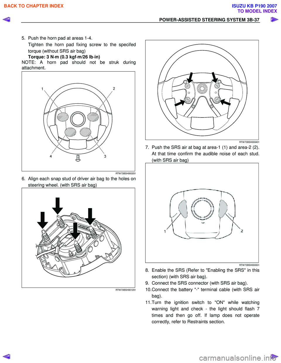
5. Push the horn pad at areas 1-4.
Tighten the horn pad fixing screw to the specifed torque (without SRS air bag)
Torque: 3 N ⋅
⋅⋅
⋅
m (0.3 kgf ⋅
⋅⋅
⋅
m/26 lb ⋅
⋅⋅
⋅
in)
NOTE: A horn pad should not be struk during
attachment.
RTW 73BSH000201
6. Align each snap stud of driver air bag to the holes on
steering wheel. (with SRS air bag)
RTW 73BSH001201
RTW 73BSH000401
7. Push the SRS air at bag at area-1 (1) and area-2 (2).
At that time confirm the audible noise of each stud.
(with SRS air bag)
RTW 73BSH000301
8. Enable the SRS (Refer to "Enabling the SRS" in this section) (with SRS air bag).
9. Connect the SRS connector (with SRS air bag).
10. Connect the battery "-" terminal cable (with SRS ai
r
bag).
11. Turn the ignition switch to "ON" while watching warning light and check - the light should flash 7
times and then go off. If lamp does not operate
correctly, refer to Restraints section.
BACK TO CHAPTER INDEX
TO MODEL INDEX
ISUZU KB P190 2007
Page 300 of 6020
POWER-ASSISTED STEERING SYSTEM 3B-39
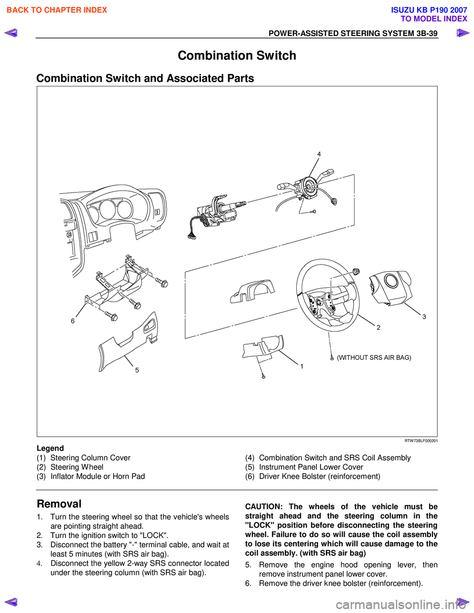
Combination Switch
Combination Switch and Associated Parts
RTW 73BLF000201
Legend
(1) Steering Column Cover
(2) Steering W heel
(3) Inflator Module or Horn Pad
(4) Combination Switch and SRS Coil Assembly
(5) Instrument Panel Lower Cover
(6) Driver Knee Bolster (reinforcement)
Removal
1. Turn the steering wheel so that the vehicle's wheels are pointing straight ahead.
2. Turn the ignition switch to "LOCK".
3. Disconnect the battery "-" terminal cable, and wait at least 5 minutes (with SRS air bag).
4. Disconnect the yellow 2-way SRS connector located
under the steering column (with SRS air bag).
CAUTION: The wheels of the vehicle must be
straight ahead and the steering column in the
"LOCK" position before disconnecting the steering
wheel. Failure to do so will cause the coil assembly
to lose its centering which will cause damage to the
coil assembly. (with SRS air bag)
5. Remove the engine hood opening lever, then remove instrument panel lower cover.
6. Remove the driver knee bolster (reinforcement).
BACK TO CHAPTER INDEX
TO MODEL INDEX
ISUZU KB P190 2007
Page 305 of 6020
3B-44 POWER-ASSISTED STEERING SYSTEM
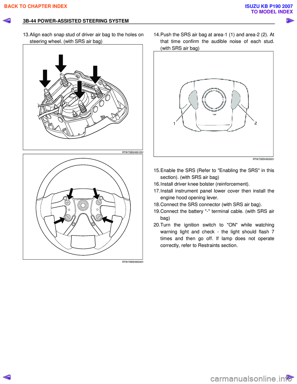
13. Align each snap stud of driver air bag to the holes on
steering wheel. (with SRS air bag)
RTW 73BSH001201
RTW 73BSH000401
14. Push the SRS air bag at area-1 (1) and area-2 (2). At
that time confirm the audible noise of each stud.
(with SRS air bag)
RTW 73BSH000301
15. Enable the SRS (Refer to "Enabling the SRS" in this
section). (with SRS air bag)
16. Install driver knee bolster (reinforcement).
17. Install instrument panel lower cover then install the engine hood opening lever.
18. Connect the SRS connector (with SRS air bag).
19. Connect the battery "-" terminal cable. (with SRS ai
r
bag)
20. Turn the ignition switch to "ON" while watching warning light and check - the light should flash 7
times and then go off. If lamp does not operate
correctly, refer to Restraints section.
BACK TO CHAPTER INDEX
TO MODEL INDEX
ISUZU KB P190 2007
Page 306 of 6020
POWER-ASSISTED STEERING SYSTEM 3B-45
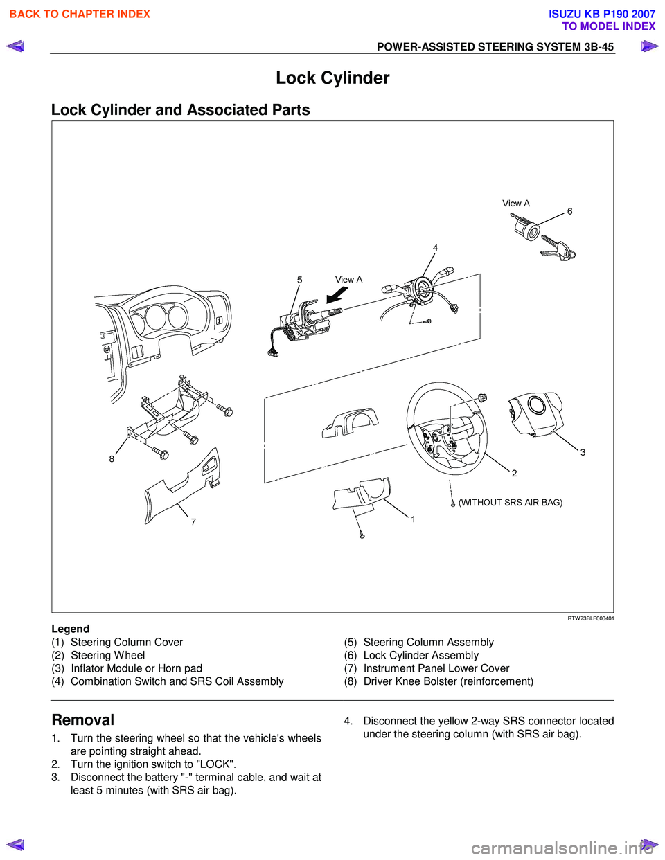
Lock Cylinder
Lock Cylinder and Associated Parts
RTW 73BLF000401
Legend
(1) Steering Column Cover
(2) Steering W heel
(3) Inflator Module or Horn pad
(4) Combination Switch and SRS Coil Assembly
(5) Steering Column Assembly
(6) Lock Cylinder Assembly
(7) Instrument Panel Lower Cover
(8) Driver Knee Bolster (reinforcement)
Removal
1. Turn the steering wheel so that the vehicle's wheels are pointing straight ahead.
2. Turn the ignition switch to "LOCK".
3. Disconnect the battery "-" terminal cable, and wait at least 5 minutes (with SRS air bag).
4. Disconnect the yellow 2-way SRS connector located
under the steering column (with SRS air bag).
BACK TO CHAPTER INDEX
TO MODEL INDEX
ISUZU KB P190 2007
Page 309 of 6020
3B-48 POWER-ASSISTED STEERING SYSTEM
430R300007
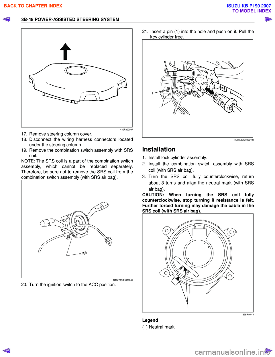
17. Remove steering column cover.
18. Disconnect the wiring harness connectors located under the steering column.
19. Remove the combination switch assembly with SRS coil.
NOTE: The SRS coil is a part of the combination switch
assembly, which cannot be replaced separately.
Therefore, be sure not to remove the SRS coil from the
combination switch assembly (with SRS air bag).
RTW 73BSH001001
20. Turn the ignition switch to the ACC position.
21. Insert a pin (1) into the hole and push on it. Pull the
key cylinder free.
RUW 53BSH000101
Installation
1. Install lock cylinder assembly.
2. Install the combination switch assembly with SRS coil (with SRS air bag).
3. Turn the SRS coil fully counterclockwise, return about 3 turns and align the neutral mark (with SRS
air bag).
CAUTION: When turning the SRS coil fully
counterclockwise, stop turning if resistance is felt.
Further forced turning may damage the cable in the
SRS coil (with SRS air bag).
826RW 014
Legend
(1) Neutral mark
BACK TO CHAPTER INDEX
TO MODEL INDEX
ISUZU KB P190 2007
Page 311 of 6020
3B-50 POWER-ASSISTED STEERING SYSTEM
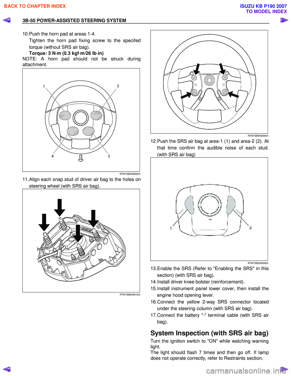
10. Push the horn pad at areas 1-4.
Tighten the horn pad fixing screw to the specifed torque (without SRS air bag).
Torque: 3 N ⋅
⋅⋅
⋅
m (0.3 kgf ⋅
⋅⋅
⋅
m/26 lb ⋅
⋅⋅
⋅
in)
NOTE: A horn pad should not be struck during
attachment.
RTW 73BSH000201
11. Align each snap stud of driver air bag to the holes on
steering wheel (with SRS air bag).
RTW 73BSH001201
RTW 73BSH000401
12. Push the SRS air bag at area-1 (1) and area-2 (2). At that time confirm the audible noise of each stud.
(with SRS air bag)
RTW 73BSH000301
13. Enable the SRS (Refer to "Enabling the SRS" in this section) (with SRS air bag).
14. Install driver knee bolster (reinforcement).
15. Install instrument panel lower cover, then install the engine hood opening lever.
16. Connect the yellow 2-way SRS connector located under the steering column (with SRS air bag).
17. Connect the battery "-" terminal cable (with SRS ai
r
bag).
System Inspection (with SRS air bag)
Turn the ignition switch to "ON" while watching warning
light.
The light should flash 7 times and then go off. If lamp
does not operate correctly, refer to Restraints section.
BACK TO CHAPTER INDEX
TO MODEL INDEX
ISUZU KB P190 2007
Page 312 of 6020
POWER-ASSISTED STEERING SYSTEM 3B-51
Steering Column
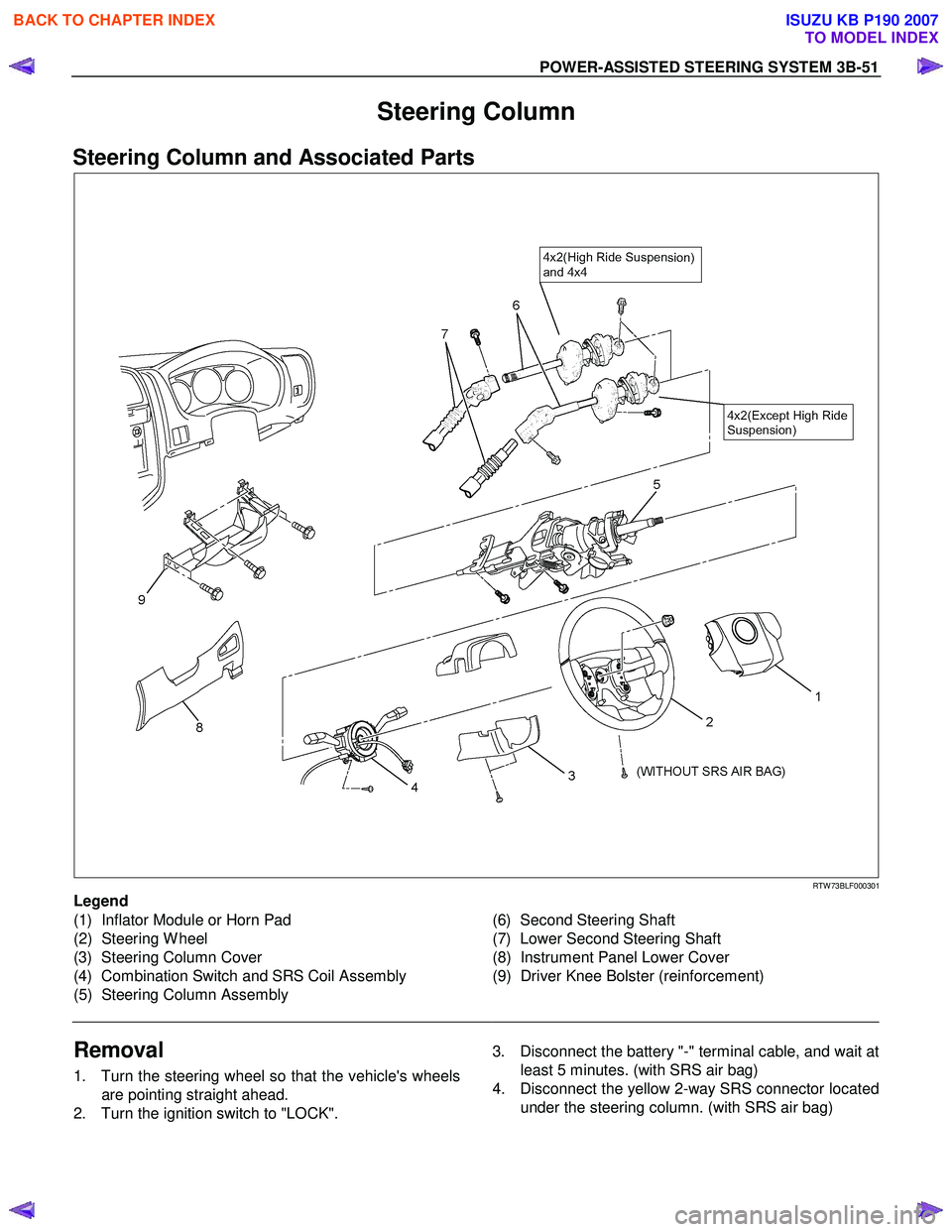
Steering Column and Associated Parts
RTW 73BLF000301
Legend
(1) Inflator Module or Horn Pad
(2) Steering W heel
(3) Steering Column Cover
(4) Combination Switch and SRS Coil Assembly
(5) Steering Column Assembly
(6) Second Steering Shaft
(7) Lower Second Steering Shaft
(8) Instrument Panel Lower Cover
(9) Driver Knee Bolster (reinforcement)
Removal
1. Turn the steering wheel so that the vehicle's wheels are pointing straight ahead.
2. Turn the ignition switch to "LOCK".
3. Disconnect the battery "-" terminal cable, and wait at
least 5 minutes. (with SRS air bag)
4. Disconnect the yellow 2-way SRS connector located under the steering column. (with SRS air bag)
BACK TO CHAPTER INDEX
TO MODEL INDEX
ISUZU KB P190 2007
Page 318 of 6020
POWER-ASSISTED STEERING SYSTEM 3B-57
System Inspection (with SRS air bag)
Turn the ignition switch to "ON" while watching warning
light.
The light should flash 7 times and then go off. If lamp
does not operate correctly, refer to Restraints section.
BACK TO CHAPTER INDEX
TO MODEL INDEX
ISUZU KB P190 2007
Page 607 of 6020

5A-14 BRAKE CONTROL SYSTEM
Connector List
No. Connector face No. Connector face
B-23
White
Meter-A C-36
SilverEngine room - LH ; Ground
B-24
White
Meter-B C-44
WhiteStoplight switch
B-48
Black
G sensor C-53
OrangeABS sensor Front-RH
B-54
White
J/B I2 C-54
OrangeABS sensor Front-LH
B-56
White
J/B I4 C-67
Black
EHCU
B-58
Black
Data link connector C-107
WhiteJ/B E2
B-62
White
Ignition switch (IGSUB : G1) C-108
WhiteJ/B E1
B-63
White
Ignition switch (IGSUB : G2) C-109
SilverBody-LH ; ground
B-82
Silver
W eld splice 6 (Ground) C-111
BlackTransfer case control module
C-2
Silver
Engine room - RH ground F-4
Gray ABS sensor
BACK TO CHAPTER INDEX
TO MODEL INDEX
ISUZU KB P190 2007
Page 615 of 6020
5A-22 BRAKE CONTROL SYSTEM
System Components
Electronic Hydraulic Control Unit (EHCU), four W heel
Speed Sensors, two W arning Lamps, and G sensor.
Electronic Hydraulic Control Unit (EHCU)
The EHCU consists of ABS control circuits, fault
detector, and a fail-safe. It drives the EHCU according
to the signal from each sensor, cancelling ABS to return
to normal braking when a malfunction has occurred in
the ABS.
The EHCU has a self-diagnosing function which can
indicate faulty circuits during diagnosis.
The EHCU is mounted on the engine compartment rear
left side. It consists of a motor, solenoid valves and a
fail safe relay.
Solenoid Valves: Reduces or holds the caliper fluid
pressure for each front brake or both rear brakes
according to the signal sent from the EHCU.
Buffer chamber: Temporarily holds the brake fluid that
returns from the front and rear brake so that pressure of
front brake can be reduced smoothly.
Motor: Drives the pump according to the signal from
EHCU.
Fail safe Relay: W hen failure occurs in ABS.
The power supply to solenoid Valve is cut.
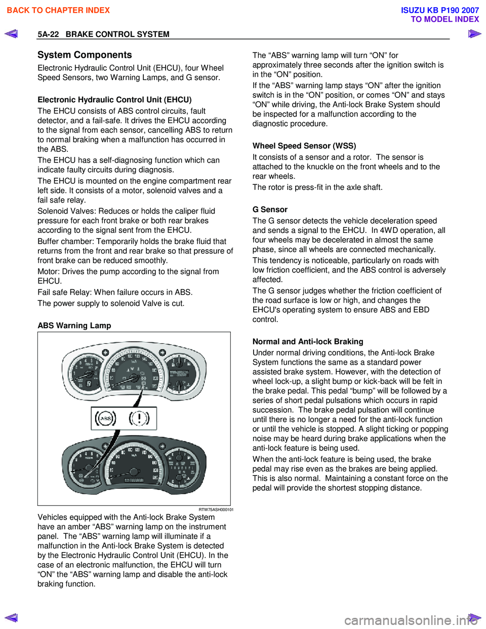
ABS Warning Lamp
RTW 75ASH000101
Vehicles equipped with the Anti-lock Brake System
have an amber “ABS” warning lamp on the instrument
panel. The “ABS” warning lamp will illuminate if a
malfunction in the Anti-lock Brake System is detected
by the Electronic Hydraulic Control Unit (EHCU). In the
case of an electronic malfunction, the EHCU will turn
“ON” the “ABS” warning lamp and disable the anti-lock
braking function.
The “ABS” warning lamp will turn “ON” for
approximately three seconds after the ignition switch is
in the “ON” position.
If the “ABS” warning lamp stays “ON” after the ignition
switch is in the “ON” position, or comes “ON” and stays
“ON” while driving, the Anti-lock Brake System should
be inspected for a malfunction according to the
diagnostic procedure.
Wheel Speed Sensor (WSS)
It consists of a sensor and a rotor. The sensor is
attached to the knuckle on the front wheels and to the
rear wheels.
The rotor is press-fit in the axle shaft.
G Sensor
The G sensor detects the vehicle deceleration speed
and sends a signal to the EHCU. In 4W D operation, all
four wheels may be decelerated in almost the same
phase, since all wheels are connected mechanically.
This tendency is noticeable, particularly on roads with
low friction coefficient, and the ABS control is adversely
affected.
The G sensor judges whether the friction coefficient of
the road surface is low or high, and changes the
EHCU's operating system to ensure ABS and EBD
control.
Normal and Anti-lock Braking
Under normal driving conditions, the Anti-lock Brake
System functions the same as a standard power
assisted brake system. However, with the detection of
wheel lock-up, a slight bump or kick-back will be felt in
the brake pedal. This pedal “bump” will be followed by a
series of short pedal pulsations which occurs in rapid
succession. The brake pedal pulsation will continue
until there is no longer a need for the anti-lock function
or until the vehicle is stopped. A slight ticking or popping
noise may be heard during brake applications when the
anti-lock feature is being used.
W hen the anti-lock feature is being used, the brake
pedal may rise even as the brakes are being applied.
This is also normal. Maintaining a constant force on the
pedal will provide the shortest stopping distance.
BACK TO CHAPTER INDEX
TO MODEL INDEX
ISUZU KB P190 2007