warning ISUZU KB P190 2007 Workshop User Guide
[x] Cancel search | Manufacturer: ISUZU, Model Year: 2007, Model line: KB P190, Model: ISUZU KB P190 2007Pages: 6020, PDF Size: 70.23 MB
Page 308 of 6020
POWER-ASSISTED STEERING SYSTEM 3B-47
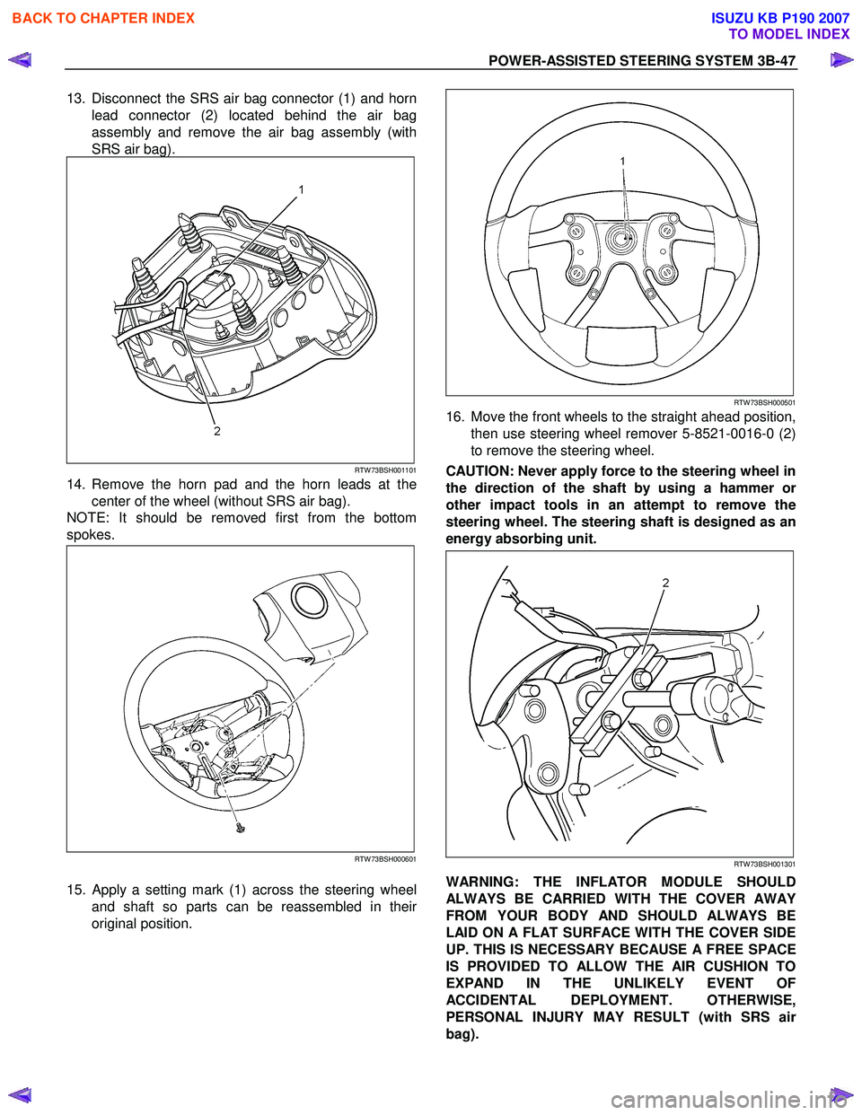
13. Disconnect the SRS air bag connector (1) and horn
lead connector (2) located behind the air bag
assembly and remove the air bag assembly (with
SRS air bag).
RTW 73BSH001101
14. Remove the horn pad and the horn leads at the center of the wheel (without SRS air bag).
NOTE: It should be removed first from the bottom
spokes.
RTW 73BSH000601
15.
Apply a setting mark (1) across the steering wheel
and shaft so parts can be reassembled in thei
r
original position.
RTW 73BSH000501
16. Move the front wheels to the straight ahead position,
then use steering wheel remover 5-8521-0016-0 (2)
to remove the steering wheel.
CAUTION: Never apply force to the steering wheel in
the direction of the shaft by using a hammer o
r
other impact tools in an attempt to remove the
steering wheel. The steering shaft is designed as an
energy absorbing unit.
RTW 73BSH001301
WARNING: THE INFLATOR MODULE SHOULD
ALWAYS BE CARRIED WITH THE COVER AWAY
FROM YOUR BODY AND SHOULD ALWAYS BE
LAID ON A FLAT SURFACE WITH THE COVER SIDE
UP. THIS IS NECESSARY BECAUSE A FREE SPACE
IS PROVIDED TO ALLOW THE AIR CUSHION TO
EXPAND IN THE UNLIKELY EVENT OF
ACCIDENTAL DEPLOYMENT. OTHERWISE,
PERSONAL INJURY MAY RESULT (with SRS ai
r
bag).
BACK TO CHAPTER INDEX
TO MODEL INDEX
ISUZU KB P190 2007
Page 311 of 6020
3B-50 POWER-ASSISTED STEERING SYSTEM
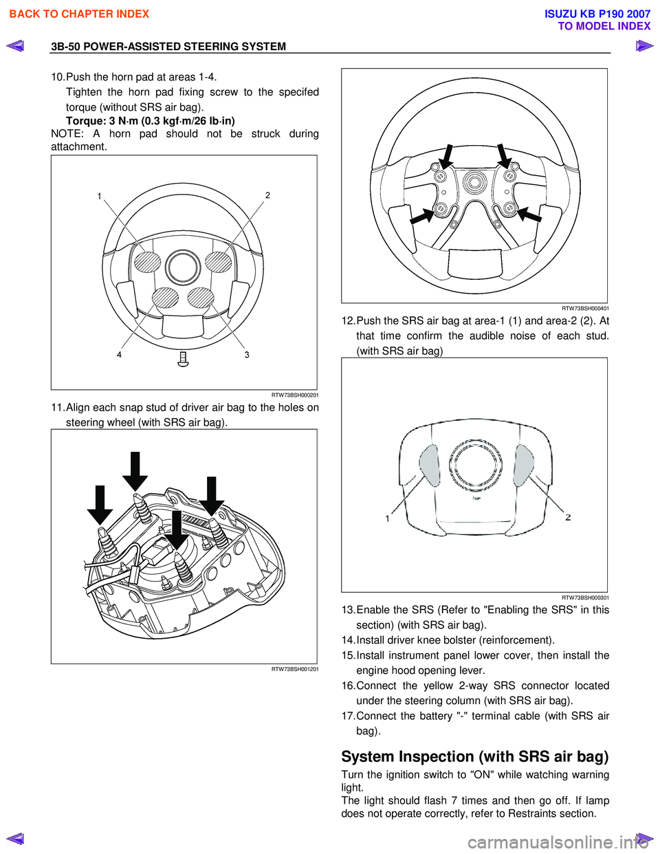
10. Push the horn pad at areas 1-4.
Tighten the horn pad fixing screw to the specifed torque (without SRS air bag).
Torque: 3 N ⋅
⋅⋅
⋅
m (0.3 kgf ⋅
⋅⋅
⋅
m/26 lb ⋅
⋅⋅
⋅
in)
NOTE: A horn pad should not be struck during
attachment.
RTW 73BSH000201
11. Align each snap stud of driver air bag to the holes on
steering wheel (with SRS air bag).
RTW 73BSH001201
RTW 73BSH000401
12. Push the SRS air bag at area-1 (1) and area-2 (2). At that time confirm the audible noise of each stud.
(with SRS air bag)
RTW 73BSH000301
13. Enable the SRS (Refer to "Enabling the SRS" in this section) (with SRS air bag).
14. Install driver knee bolster (reinforcement).
15. Install instrument panel lower cover, then install the engine hood opening lever.
16. Connect the yellow 2-way SRS connector located under the steering column (with SRS air bag).
17. Connect the battery "-" terminal cable (with SRS ai
r
bag).
System Inspection (with SRS air bag)
Turn the ignition switch to "ON" while watching warning
light.
The light should flash 7 times and then go off. If lamp
does not operate correctly, refer to Restraints section.
BACK TO CHAPTER INDEX
TO MODEL INDEX
ISUZU KB P190 2007
Page 318 of 6020
POWER-ASSISTED STEERING SYSTEM 3B-57
System Inspection (with SRS air bag)
Turn the ignition switch to "ON" while watching warning
light.
The light should flash 7 times and then go off. If lamp
does not operate correctly, refer to Restraints section.
BACK TO CHAPTER INDEX
TO MODEL INDEX
ISUZU KB P190 2007
Page 328 of 6020
3C-8 FRONT SUSPENSION
Service Precaution
WARNING: THIS VEHICLE HAS A SUPPLEMENTAL
RESTRAINT SYSTEM (SRS). REFER TO THE SRS
COMPONENT AND WIRING LOCATION VIEW IN
ORDER TO DETERMINE WHETHER YOU ARE
PERFORMING SERVICE ON OR NEAR THE SRS
COMPONENTS OR THE SRS WIRING. WHEN YOU
ARE PERFORMING SERVICE ON OR NEAR THE
SRS COMPONENTS OR THE SRS WIRING, REFER
TO THE SRS SERVICE INFORMATION. FAILURE TO
FOLLOW WARNINGS COULD RESULT IN
POSSIBLE AIR BAG DEPLOYMENT, PERSONAL
INJURY, OR OTHERWISE UNNEEDED SRS SYSTEM
REPAIRS.
CAUTION: Always use the correct fastener in the
proper location. When you replace a fastener, use
ONLY the exact part number for that application.
ISUZU/GM will indicate those fasteners that require
replacement after removal. ISUZU/GM will also
indicate the fasteners that require thread lockers o
r
thread sealant. UNLESS OTHERWISE SPECIFIED,
do not use supplemental coatings (paints, greases,
or other corrosion inhibitors) on threaded fasteners
or fastener joint interfaces. Generally, such
coatings adversely affect the fastener torque and
the joint clamping force, and may damage the
fastener. When you install fasteners, use the
correct tightening sequence and specifications.
Following these instructions can help you avoid
damage to parts and systems.
BACK TO CHAPTER INDEX
TO MODEL INDEX
ISUZU KB P190 2007
Page 351 of 6020
3C-30 FRONT SUSPENSION
Service Precaution
WARNING: THIS VEHICLE HAS A SUPPLEMENTAL
RESTRAINT SYSTEM (SRS). REFER TO THE SRS
COMPONENT AND WIRING LOCATION VIEW IN
ORDER TO DETERMINE WHETHER YOU ARE
PERFORMING SERVICE ON OR NEAR THE SRS
COMPONENTS OR THE SRS WIRING. WHEN YOU
ARE PERFORMING SERVICE ON OR NEAR THE
SRS COMPONENTS OR THE SRS WIRING, REFER
TO THE SRS SERVICE INFORMATION. FAILURE TO
FOLLOW WARNINGS COULD RESULT IN
POSSIBLE AIR BAG DEPLOYMENT, PERSONAL
INJURY, OR OTHERWISE UNNECESSARY SRS
SYSTEM REPAIRS.
CAUTION: Always use the correct fastener in the
proper location. When you replace a fastener, use
ONLY the exact part number for that application.
ISUZU/GM will call out those fasteners that require
a replacement after removal. ISUZU/GM will also
call out the fasteners that require thread lockers o
r
thread sealant. UNLESS OTHERWISE SPECIFIED,
do not use supplemental coatings (paints, greases,
or other corrosion inhibitors) on threaded fasteners
or fastener joint interfaces. Generally, such
coatings adversely affect the fastener torque and
the joint clamping force, and may damage the
fastener. When you install fasteners, use the
correct tightening sequence and specifications.
Following these instructions can help you avoid
damage to parts and systems.
BACK TO CHAPTER INDEX
TO MODEL INDEX
ISUZU KB P190 2007
Page 418 of 6020

4A-2 PROPELLER SHAFT
Service Precaution
WARNING: THIS VEHICLE HAS A
SUPPLEMENTAL RESTRAINT SYSTEM (SRS).
REFER TO THE SRS COMPONENT AND WIRING
LOCATION VIEW IN ORDER TO DETERMINE
WHETHER YOU ARE PERFORMING SERVICE ON
OR NEAR THE SRS COMPONENTS OR THE SRS
WIRING. WHEN YOU ARE PERFORMING
SERVICE ON OR NEAR THE SRS COMPONENTS
OR THE SRS WIRING, REFER TO THE SRS
SERVICE INFORMATION. FAILURE TO FOLLOW
WARNING COULD RESULT IN POSSIBLE AIR
BAG DEPLOYMENT, PERSONAL INJURY, OR
OTHERWISE UNNEEDED SRS SYSTEM
REPAIRS.
CAUTION : Always use the correct fastener in the
proper location. When you replace a fastener,
use ONLY the exact part number for that
application. ISUZU/GM will call out those
fasteners that require a replacement afte
r
removal. ISUZU/GM will also call out the
fasteners that require thread lockers or thread
sealant. UNLESS OTHERWISE SPECIFIED, do
not use supplemental coatings (Paints, greases,
or other corrosion inhibitors) on threaded
fasteners or fastener joint interfaces. Generally,
such coatings adversely affect the fastene
r
torque and the joint clamping force, and may
damage the fastener. When you install fasteners,
use the correct tightening sequence and
specifications. Following these instructions can
help you avoid damage to parts and systems.
BACK TO CHAPTER INDEX
TO MODEL INDEX
ISUZU KB P190 2007
Page 446 of 6020

4B-2 REAR AXLE
Service Precaution
WARNING:
THIS VEHICLE HAS A SUPPLEMENTAL
RESTRAINT SYSTEM (SRS). REFER TO THE SRS
COMPONENT AND WIRING LOCATION VIEW IN
ORDER TO DETERMINE WHETHER YOU ARE
PERFORMING SERVICE ON OR NEAR THE SRS
COMPONENTS OR THE SRS WIRING. WHEN YOU
ARE REFORMING SERVICE ON OR NEAR THE
SRS COMPONENTS OR THE SRS WIRING, REFER
TO THE SRS SERVICE INFORMATION. FAILURE
TO FOLLOW WARNINGS COULD RESULT IN
POSSIBLE AIR BAG DEPLOYMENT, PERSONAL
INJURY, OR OTHERWISE UNNEEDED SRS
SYSTEM REPAIRS.
CAUTION:
Always use the correct fastener in the prope
r
location. When you replace a fastener, use ONLY
the exact part number for that application.
ISUZU/GM will call out those fasteners that require
a replacement after removal. ISUZU/GM will also
call out the fasteners that require thread lockers o
r
thread sealant. UNLESS OTHERWISE SPECIFIED,
do not use supplemental coatings (Paints,
greases, or other corrosion inhibitors) on threaded
fasteners or fastener joint interfaces. Generally,
such coatings adversely affect the fastener torque
and the joint clamping force, and may damage the
fastener. When you install fasteners, use the
correct tightening sequence and specification.
Following these instructions can help you avoid
damage to parts and systems.
BACK TO CHAPTER INDEX
TO MODEL INDEX
ISUZU KB P190 2007
Page 579 of 6020

SHIFT ON THE FLY SYSTEM 4C2-1
SERVICE PRECAUTION
WARNING: THIS VEHICLE HAS A SUPPLEMENTAL
RESTRAINT SYSTEM (SRS). REFER TO THE SRS
COMPONENT AND WIRING LOCATION VIEW IN
ORDER TO DETERMINE WHETHER YOU ARE
PERFORMING SERVICE ON OR NEAR THE SRS
COMPONENTS OR THE SRS WIRING. WHEN YOU
ARE PERFORMING SERVICE ON OR NEAR THE
SRS COMPONENTS OR THE SRS WIRING, REFER
TO THE SRS SERVICE INFORMATION. FAILURE TO
FOLLOW WARNINGS COULD RESULT IN
POSSIBLE AIR BAG DEPLOYMENT, PERSONAL
INJURY, OR OTHERWISE UNNEEDED SRS SYSTEM
REPAIRS.
CAUTION: Always use the correct fastener in the
proper location. When you replace a fastener, use
ONLY the exact part number for that application.
ISUZU/GM will call out those fasteners that require
a replacement after removal. ISUZU/GM will also
call out the fasteners that require thread lockers o
r
thread sealant. UNLESS OTHERWISE SPECIFIED,
do not use supplemental coatings (Paints, greases,
or other corrosion inhibitors) on threaded fasteners
or fastener joint interfaces. Generally, such
coatings adversely affect the fastener torque and
the joint clamping force, and may damage the
fastener. When you install fasteners, use the
correct tightening sequence and specifications.
Following these instructions can help you avoid
damage to parts and systems.
BACK TO CHAPTER INDEX
TO MODEL INDEX
ISUZU KB P190 2007
Page 593 of 6020
BRAKE CON TROL SY STE M 5 A
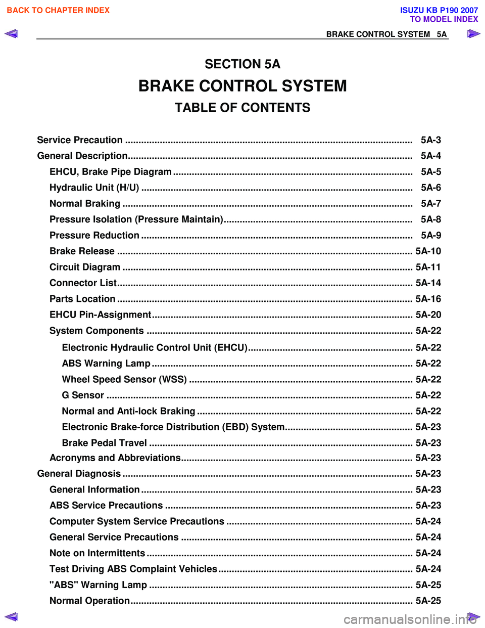
EHCU, Brake Pipe Diagram .......................................................................................... 5A-5
Hydraulic Unit (H/U) ...................................................................................................... 5A-6
Normal Braking ............................................................................................................. 5A- 7
Pressure Isolation (Pressure Maintain)....................................................................... 5A-8
Pressure Reduction ...................................................................................................... 5A-9
Brake Release ............................................................................................................... 5A -10
Circuit Diagram ............................................................................................................. 5A -11
Connector List ............................................................................................................... 5 A-14
Parts Location ............................................................................................................... 5 A-16
EHCU Pin-Assignment .................................................................................................. 5A-20
System Components .................................................................................................... 5A-22
Electronic Hydraulic Control Unit (EHCU).............................................................. 5A-22
ABS Warning Lamp .................................................................................................. 5A-22
Wheel Speed Sensor (WSS) .................................................................................... 5A-22
G Sensor ................................................................................................................... 5A- 22
Normal and Anti-lock Braking ................................................................................. 5A-22
Electronic Brake-force Distribution (EBD) System................................................ 5A-23
Brake Pedal Travel ................................................................................................... 5A-23
Acronyms and Abbreviations....................................................................................... 5A-23
General Diagnosis ............................................................................................................. 5A-23
General Information ...................................................................................................... 5A-23
ABS Service Precautions ............................................................................................. 5A-23
Computer System Service Precautions ...................................................................... 5A-24
General Service Precautions ....................................................................................... 5A-24
Note on Intermittents .................................................................................................... 5A-24
Test Driving ABS Complaint Vehicles ......................................................................... 5A-24
"ABS" Warning Lamp ................................................................................................... 5A-25
Normal Operation .......................................................................................................... 5A-2 5
SECTION 5A
BRAKE CONTROL SYSTEM
TABLE OF CONTENTS
Ser vice Precau tion ............................................................................................................ 5A -3
General Descrip tio n........................................................................................................... 5A -4
BACK TO CHAPTER INDEX
TO MODEL INDEX
ISUZU KB P190 2007
Page 594 of 6020

5A -1 BR AKE CON TROL SY STE M
Brake (E BD) Warning Lamp ......................................................................................... 5 A -25
Tech 2 Scan Tool .......................................................................................................... 5 A -2 6
Da ta List ( T ech 2 ).......................................................................................................... 5 A -32
Diagnostic Trouble Codes ................................................................................................ 5 A -33
Diagnosis By " A BS" Warning Lamp Illumination Patter n.............................................. 5 A -35
Basic Diagnostic Flow Chart ............................................................................................ 5 A -38
Basic Inspec tion Procedure ............................................................................................. 5 A -40
1. Basic Inspec tion of Ser vice Brake .......................................................................... 5 A -40
2. Ground Inspection .................................................................................................... 5 A -40
W heel Speed Sensor Inspec tion Procedure.................................................................... 5 A -41
Symptom Diagnosis .......................................................................................................... 5A- 42
ABS Works Frequently But Vehicle Does Not Decelerate ......................................... 5A-42
Uneven Braking Occurs While ABS Works ................................................................ 5A-43
The Wheels Are Locked................................................................................................ 5A-43
Brake Pedal Feed Is Abnormal .................................................................................... 5A-44
Braking Sound (From EHCU) Is Heard While Not Braking ........................................ 5A-45
No ABS Warning Lamp ................................................................................................. 5A-46
ABS Warning Lamp ON Steady.................................................................................... 5A-47
DTC C0221 (Flash Code 21) Front Right Wheel Speed Sensor
Short Circuit or Circuit Open ......................................................................................... 5A-48
DTC C0222 (Flash Code 22) Front Right Wheel Speed Sensor Signal Malfunction..... 5A-50
DTC C0225 (Flash Code 25) Front Left Wheel Speed Sensor Short Circuit or
Circuit Open ................................................................................................................ .... 5A-52
DTC C0226 (Flash Code 26) Front Left Wheel Speed Sensor Signal Malfunction ....... 5A-54
DTC C0231 (Flash Code 31) Rear Right Wheel Speed Sensor Short Circuit or
Circuit Open ................................................................................................................ .... 5A-56
DTC C0232 (Flash Code 32) Rear Right Wheel Speed Sensor Signal Malfunction ...... 5A-58
DTC C0235 (Flash Code 35) Rear Left Wheel Speed Sensor Short Circuit or
Circuit Open ................................................................................................................ .... 5A-60
DTC C0236 (Flash Code 36) Rear Left Wheel Speed Sensor Signal Malfunction ........ 5A-62
DTC C0238 (Flash Code 38) Front Speed Sensor Correlation ....................................... 5A-64
DTC C0241 (Flash Code 41) Front Right Hold Solenoid Valve Circuit .......................... 5A-66
DTC C0242 (Flash Code 42) Front Right Release Solenoid Valve Circuit..................... 5A-66
DTC C0245 (Flash Code 45) Front Left Hold Solenoid Valve Circuit ............................. 5A-68
DTC C0246 (Flash Code 46) Front Left Release Solenoid Valve Circuit ....................... 5A-68
BACK TO CHAPTER INDEX
TO MODEL INDEX
ISUZU KB P190 2007