Diagram ISUZU KB P190 2007 Workshop Repair Manual
[x] Cancel search | Manufacturer: ISUZU, Model Year: 2007, Model line: KB P190, Model: ISUZU KB P190 2007Pages: 6020, PDF Size: 70.23 MB
Page 4266 of 6020
CONSTRUCTION AND FUNCTION 7A1-27
Item Description
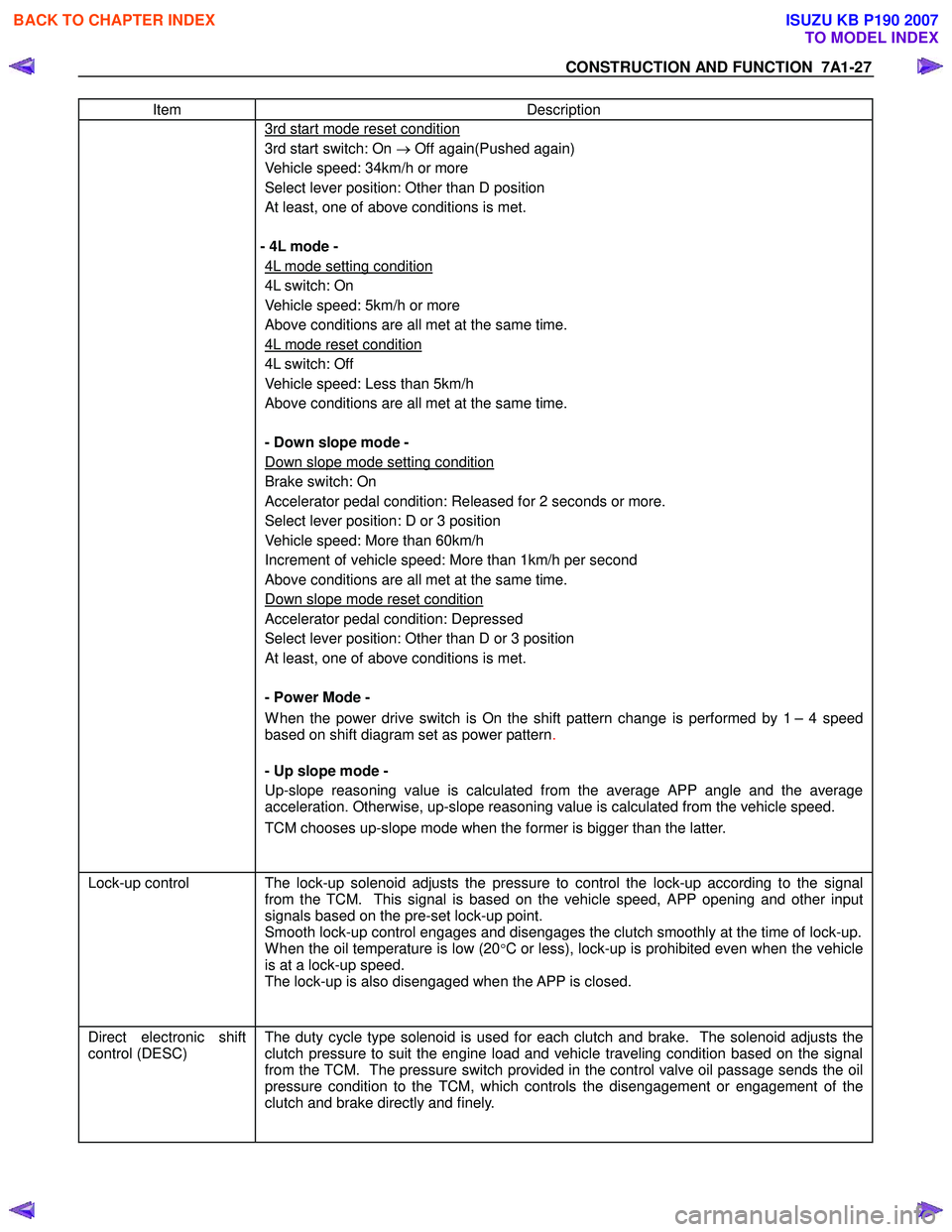
3rd start mode reset condition
3rd start switch: On → Off again(Pushed again)
Vehicle speed: 34km/h or more
Select lever position: Other than D position
At least, one of above conditions is met.
- 4L mode -
4L mode setting condition
4L switch: On
Vehicle speed: 5km/h or more
Above conditions are all met at the same time.
4L mode reset condition
4L switch: Off
Vehicle speed: Less than 5km/h
Above conditions are all met at the same time.
- Down slope mode -
Down slope mode setting condition
Brake switch: On
Accelerator pedal condition: Released for 2 seconds or more.
Select lever position: D or 3 position
Vehicle speed: More than 60km/h
Increment of vehicle speed: More than 1km/h per second
Above conditions are all met at the same time.
Down slope mode reset condition
Accelerator pedal condition: Depressed
Select lever position: Other than D or 3 position
At least, one of above conditions is met.
- Power Mode -
W hen the power drive switch is On the shift pattern change is performed by 1 – 4 speed
based on shift diagram set as power pattern .
- Up slope mode -
Up-slope reasoning value is calculated from the average APP angle and the average
acceleration. Otherwise, up-slope reasoning value is calculated from the vehicle speed.
TCM chooses up-slope mode when the former is bigger than the latter.
Lock-up control The lock-up solenoid adjusts the pressure to control the lock-up according to the signal
from the TCM. This signal is based on the vehicle speed, APP opening and other input
signals based on the pre-set lock-up point.
Smooth lock-up control engages and disengages the clutch smoothly at the time of lock-up.
W hen the oil temperature is low (20°C or less), lock-up is prohibited even when the vehicle
is at a lock-up speed.
The lock-up is also disengaged when the APP is closed.
Direct electronic shift
control (DESC)
The duty cycle type solenoid is used for each clutch and brake. The solenoid adjusts the
clutch pressure to suit the engine load and vehicle traveling condition based on the signal
from the TCM. The pressure switch provided in the control valve oil passage sends the oil
pressure condition to the TCM, which controls the disengagement or engagement of the
clutch and brake directly and finely.
BACK TO CHAPTER INDEX
TO MODEL INDEX
ISUZU KB P190 2007
Page 4274 of 6020

CONSTRUCTION AND FUNCTION 7A1-35
CONTROL CIRCUIT BLOCK DIAGRAM
Speed sensor
Turbine sensor
Brake switch
Inhibitor switch
Power drive, 3rd start
switch
ATF oil thermo sensor
High clutch oil pressure
switch
2-4 brake oil pressure
switch
Low & reverse brake oil
pressure switch
Transfer control module
(4W D Only)
Engine Control Module
(ECM)
Line pressure solenoid
Low clutch solenoid
High clutch solenoid
2-4 brake solenoid
Low & reverse brake
solenoid
Lock-up solenoid
ATF temperature
indicator lamp
Speed meter (2W D
Only)
Power, 3rd start indicator
lamp
Check trans indicator
lamp
Data link connector Self-diagnosis
function
Transmission
Control
Module (TCM)
4L mode
Tachometer
signal output
APP PW M
position signal
output
Figure 54. Control Circuit Block Diagram
BACK TO CHAPTER INDEX
TO MODEL INDEX
ISUZU KB P190 2007
Page 4285 of 6020
TRANSMISSION CONTROL SYSTEM (JR405E) 7A2-1
TRANSMISSION
TRANSMISSION CONTROL SYSTEM (JR405E)
This manual conforms when Scan Tool of ISO CAN Base Software is used.
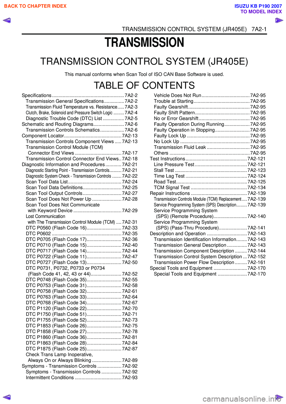
TABLE OF CONTENTS
Specifications ...................................................... 7A2-2Transmission General Specifications ............... 7A2-2
Transmission Fluid Temperature vs. Resistance..... 7A2-3
Clutch, Brake, Solenoid and Pressure Switch Logic........ 7A2-4
Diagnostic Trouble Code (DTC) List ................ 7A2-5
Schematic and Routing Diagrams....................... 7A2-6 Transmission Controls Schematics .................. 7A2-6
Component Locator........................................... 7A2-13 Transmission Controls Component Views ..... 7A2-13
Transmission Control Module (TCM) Connector End Views ................................... 7A2-17
Transmission Control Connector End Views.. 7A2-18
Diagnostic Information and Procedures ............ 7A2-21
Diagnostic Starting Point - Transmission Controls......... 7A2-21
Diagnostic System Check - Transmission Controls....... 7A2-22
Scan Tool Data List ........................................ 7A2-24
Scan Tool Data Definitions............................. 7A2-25
Scan Tool Output Controls ............................. 7A2-27
Scan Tool Does Not Power Up ...................... 7A2-28
Scan Tool Does Not Communicate with Keyword Device .................................... 7A2-29
Lost Communication with The Transmission Control Module (TCM)
.... 7A2-31
DTC P0560 (Flash Code 16).......................... 7A2-33
DTC P0602 .................................................... 7A2-35
DTC P0705 (Flash Code 17).......................... 7A2-36
DTC P0710 (Flash Code 15).......................... 7A2-40
DTC P0717 (Flash Code 14).......................... 7A2-44
DTC P0722 (Flash Code 11).......................... 7A2-47
DTC P0727 (Flash Code 13).......................... 7A2-50
DTC P0731, P0732, P0733 or P0734 (Flash Code 41, 42, 43 or 44)....................... 7A2-52
DTC P0748 (Flash Code 35).......................... 7A2-55
DTC P0753 (Flash Code 31).......................... 7A2-58
DTC P0758 (Flash Code 32).......................... 7A2-61
DTC P0763 (Flash Code 33).......................... 7A2-64
DTC P0768 (Flash Code 34).......................... 7A2-67
DTC P1120 (Flash Code 22).......................... 7A2-70
DTC P1750 (Flash Code 51).......................... 7A2-71
DTC P1755 (Flash Code 52).......................... 7A2-73
DTC P1853 (Flash Code 26).......................... 7A2-75
DTC P1858 (Flash Code 27).......................... 7A2-78
DTC P1860 (Flash Code 36).......................... 7A2-81
DTC P1863 (Flash Code 28).......................... 7A2-84
DTC P1875 (Flash Code 25).......................... 7A2-87
Check Trans Lamp Inoperative, Always On or Always Blinking ...................... 7A2-89
Symptoms - Transmission Controls .................. 7A2-92 Symptoms - Transmission Controls ............... 7A2-92
Intermittent Conditions ................................... 7A2-93 Vehicle Does Not Run .................................... 7A2-95
Trouble at Starting.......................................... 7A2-95
Faulty Gearshift .............................................. 7A2-95
Faulty Shift Pattern......................................... 7A2-95
No or Error Gearshift ...................................... 7A2-95
Faulty Operation During Running................... 7A2-95
Faulty Operation in Stopping.......................... 7A2-95
Faulty Lock Up ............................................... 7A2-95
No Lock Up .................................................... 7A2-95
Transmission Fluid Leak ................................ 7A2-95
Others ............................................................ 7A2-95
Test Instructions .............................................. 7A2-121 Line Pressure Test ....................................... 7A2-121
Stall Test ...................................................... 7A2-123
Time Lag Test .............................................. 7A2-124
Road Test..................................................... 7A2-125
TCM Signal Test .......................................... 7A2-134
Repair Instructions .......................................... 7A2-139
Transmission Controls Module (TCM) Replacement.... 7A2-139
Service Programming System (SPS) Description........ 7A2-139
Service Programming System (SPS) (Remote Procedure)......................... 7A2-140
Service Programming System (SPS) (Pass-Thru Procedure)..................... 7A2-141
Description and Operation .............................. 7A2-143 Transmission Identification Information........ 7A2-143
Transmission General Description ............... 7A2-143
Transmission Component Description ......... 7A2-144
Transmission Control System Description ... 7A2-152
Transmission Power Flow Description ......... 7A2-161
Special Tools and Equipment ......................... 7A2-170 Special Tools and Equipment ...................... 7A2-170
BACK TO CHAPTER INDEX
TO MODEL INDEX
ISUZU KB P190 2007
Page 4290 of 6020
7A2-6 TRANSMISSION CONTROL SYSTEM (JR405E)
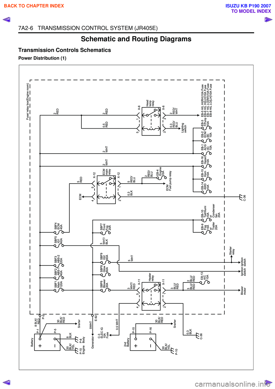
Schematic and Routing Diagrams
Transmission Controls Schematics
Power Distribution (1)
BACK TO CHAPTER INDEX
TO MODEL INDEX
ISUZU KB P190 2007
Page 4875 of 6020

TRANSFER CONTROL SYSTEM 7D1-1
SECTION 7D1
TRANSFER CONTROL SYSTEM
TABLE OF CONTENTS
PAGE
Service Precaution ..................................................................................................... 7D1 - 2
General Description ................................................................................................... 7D1 - 3
System Components .................................................................................................. 7D1 - 5 Parts Location ....................................................................................................... 7D1 - 5
Functions of Switch and Indicator Lamp ................................................................. 7D1 - 12
Parts Location ............................................................................................................ 7D1 - 24
Circuit Diagram ........................................................................................................... 7D1 - 33
Connector List ............................................................................................................ 7D1 - 41
Diagnosis .................................................................................................................... 7D1 - 46
Before determining a trouble (Non-trouble mode) ............................................ 7D1 - 46
Memory erasing procedure ....................................................................................... 7D1 - 52
Diagnosis from symptom ........................................................................................... 7D1 - 54
BACK TO CHAPTER INDEX
TO MODEL INDEX
ISUZU KB P190 2007
Page 4885 of 6020
TRANSFER CONTROL SYSTEM 7D1-11
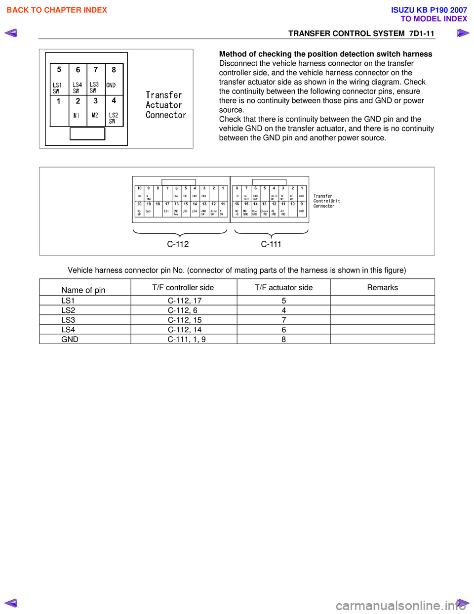
Method of checking the position detection switch harness
Disconnect the vehicle harness connector on the transfer
controller side, and the vehicle harness connector on the
transfer actuator side as shown in the wiring diagram. Check
the continuity between the following connector pins, ensure
there is no continuity between those pins and GND or power
source.
Check that there is continuity between the GND pin and the
vehicle GND on the transfer actuator, and there is no continuity
between the GND pin and another power source.
C-112 C-111
Vehicle harness connector pin No. (connector of mating parts of the harness is shown in this figure)
Name of pin T/F controller side T/F actuator side Remarks
LS1 C-112, 17 5
LS2 C-112, 6 4
LS3 C-112, 15 7
LS4 C-112, 14 6
GND C-111, 1, 9 8
BACK TO CHAPTER INDEX
TO MODEL INDEX
ISUZU KB P190 2007
Page 4907 of 6020

TRANSFER CONTROL SYSTEM 7D1-33
CIRCUIT DIAGRAM
C24SE
RTW 680XF014201
BACK TO CHAPTER INDEX
TO MODEL INDEX
ISUZU KB P190 2007
Page 4939 of 6020
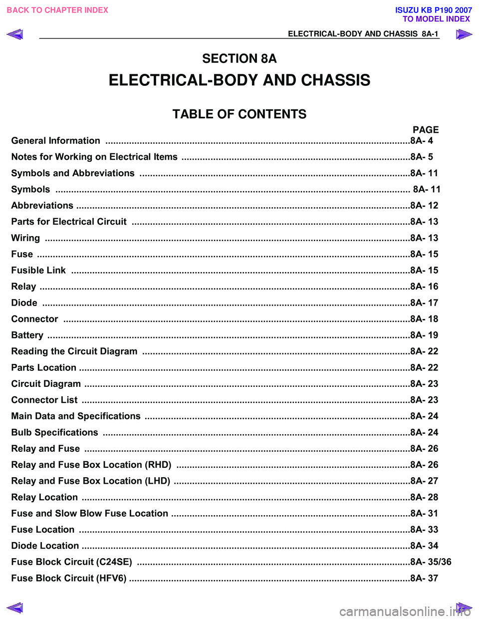
ELECTRICAL-BODY AND CHASSIS 8A-1
SECTION 8A
ELECTRICAL-BODY AND CHASSIS
TABLE OF CONTENTS
PAGE
General Information ........................................................................................................... .........8A- 4
Notes for Working on Electrical Items .......................................................................................8A - 5
Symbols and A bbreviations ..................................................................................................... ..8A- 11
Symbols ....................................................................................................................... ................ 8A- 11
Abbreviations ................................................................................................................. ..............8A- 12
Parts for Electri cal Circuit .................................................................................................. ........8A- 13
Wiring ........................................................................................................................ ...................8A- 13
Fuse .......................................................................................................................... ....................8A- 15
Fusible Link .................................................................................................................. ...............8A- 15
Relay ......................................................................................................................... ....................8A- 16
Diode ......................................................................................................................... ...................8A- 17
Connector ..................................................................................................................... ...............8A- 18
Battery ....................................................................................................................... ...................8A- 19
Reading the Circuit Diagram ................................................................................................... ...8A- 22
Parts Location ................................................................................................................ ..............8A- 22
Circuit Diagram ............................................................................................................... .............8A- 23
Connector List ................................................................................................................ .............8A- 23
Main Data and Specifications .................................................................................................. ...8A- 24
Bulb Specifications ........................................................................................................... ..........8A- 24
Relay and Fuse ................................................................................................................ ............8A- 26
Relay and Fuse Box Location (RHD) .........................................................................................8A- 26
Relay and Fuse Box Location (LHD) ..........................................................................................8A- 27
Relay Location ................................................................................................................ .............8A- 28
Fuse and Slow Blow Fuse Location ...........................................................................................8A- 31
Fuse Location ................................................................................................................. .............8A- 33
Diode Location ................................................................................................................ .............8A- 34
Fuse Block Circuit (C24SE) .................................................................................................... ....8A- 35/36
Fuse Block Circuit (HFV6) ...................................................................................................... .....8A- 37
BACK TO CHAPTER INDEX
TO MODEL INDEX
ISUZU KB P190 2007
Page 4942 of 6020

8A-4 ELECTRICAL-BODY AND CHASSIS
GENERAL INFORMATION
The body and chassis electrical system operates on a twelve volt power supply with negative ground polarity.
The main harness consists of the engine harness, the instrument harness, the body harness, and the chassis
harness.
The harnesses use a split corrugated tube to protect the wires from the elements.
W ire size is determined by current flow, circuit length, and voltage drop.
All wires have color-coded insulation.
W ire color-codes are shown in the circuit diagrams.
This makes it easier to trace circuits and to make the proper connections.
Each circuit consists of the following:
5. Power source – The battery and the alternator
5. W ires – To carry electrical current through the circuit
5. Fuses – To protect the circuit against current overload
5. Relays – To protect voltage drop between the battery and the circuit parts and to protect the switch points against burning
5. Switches – To open and close the circuit
5. Load – Any device, such as a light or motor, which converts the electrical current into useful work
5. Ground – To allow the current to flow back to the power source
BACK TO CHAPTER INDEX TO MODEL INDEXISUZU KB P190 2007
Page 4951 of 6020

ELECTRICAL-BODY AND CHASSIS 8A-13
PARTS FOR ELECTRICAL CIRCUIT
WIRING
Wire Color
All wires have color-coded insulation.
W ires belonging to system's main harness will have a single
color.
W ires belonging to a system's sub-circuits will have a colored
stripe.
Striped wires use the following code to show wire size and
colors.
Example: 0.5 G
/ R
Red (Stripe color)
Green (Base color)
W ire size (0.5mm
2)
Abbreviations are used to indicate wire color within a circuit
diagram.
Refer to the following table.
Wire Color-Coding
Color-Coding Meaning Color-Coding Meaning
B Black BR Brown
W W hite LG Light green
R Red GR Gray
G Green P Pink
Y Yellow SB Sky blue
L Blue V Violet
O Orange
BACK TO CHAPTER INDEX
TO MODEL INDEXISUZU KB P190 2007