sensor ISUZU KB P190 2007 Workshop Repair Manual
[x] Cancel search | Manufacturer: ISUZU, Model Year: 2007, Model line: KB P190, Model: ISUZU KB P190 2007Pages: 6020, PDF Size: 70.23 MB
Page 1365 of 6020

ENGINE MECHANICAL (4JK1/4JJ1) 6A-5
EGR system
Based upon data, including water temperature, engine
speeds or engine loads, it is controlled via Engine
Control Module (ECM) to purify exhaust by recycling
part of it.
Its main components include an EGR valve, an EGR
cooler and various sensors.
Connecting rod cap bolt
The angular tightening method of the connecting rod
cap bolt further increases reliability and durability.
Fuel rail-type electronic control injection system
The fuel rail-type electronic control injection system is
composed of a fuel supply pump that sets the target
pressure of high-pressure fuel and supply it, a fuel rail
that measures such high-pressure fuel and a fuel
injector that turns it into a fine spray and injects it. Each
is controlled via ECM based upon various signals, while
injection timing or fuel injection quantity is controlled
under every possible driving condition.
Fuel injector
The fuel injector is a 6-hole nozzle that adjusts fuel
injection quantity or injection timing by opening o
r
closing an electromagnetic valve on the head of the fuel
injector.
ECM corrects the dispersion of fuel injection quantit
y
between fuel injector according to ID code data in
memory. At the replacement of fuel injector, ID code
data should be stored in ECM.
Fuel filter with sedimenter
It is a fuel filter with sedimenter that gets rid of water by
making use of the difference in specific gravity between
light oil and water, which comes with an indicator that
notifies you that it is filled with water.
Preheating system
The preheating system consists of the ECM, the glow
relay, glow plugs and the glow indicator lamp. The
preheating system is operated when the engine coolant
temperature is low, and makes the engine easy to start.
Lubrication system
It is an oil filter with full-flow bypass, which uses a
water-cool oil cooler and oil jet to cool the piston.
Functional inspection
Inspection/adjustment of valve clearance 1. Inspection of valve clearance
• Remove the fuel injector harness assembly.
• Remove the leak off hose.
• Remove the cylinder head cover.
• Rotate the crankshaft to make the No.1
cylinder meet the compression top dead cente
r
(TDC).
RTW 76ASH001301
Legend
1. TDC
BACK TO CHAPTER INDEX
TO MODEL INDEX
ISUZU KB P190 2007
Page 1368 of 6020

6A-8 ENGINE MECHANICAL (4JK1/4JJ1)
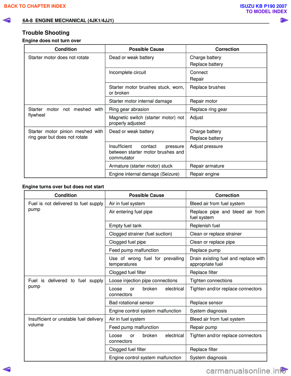
Trouble Shooting
Engine does not turn over
Condition Possible Cause Correction
Dead or weak battery Charge battery
Replace battery
Incomplete circuit Connect
Repair
Starter motor brushes stuck, worn,
or broken Replace brushes
Starter motor does not rotate
Starter motor internal damage Repair motor
Ring gear abrasion Replace ring gear Starter motor not meshed with
flywheel Magnetic switch (starter motor) not
properly adjusted Adjust
Dead or weak battery
Charge battery
Replace battery
Insufficient contact pressure
between starter motor brushes and
commutator Adjust pressure
Armature (starter motor) stuck Repair armature
Starter motor pinion meshed with
ring gear but does not rotate
Engine internal damage (Seizure) Repair engine
Engine turns over but does not start
Condition Possible Cause Correction
Air in fuel system Bleed air from fuel system
Air entering fuel pipe Replace pipe and bleed air from
fuel system
Empty fuel tank Replenish fuel
Clogged strainer (fuel suction) Clean or replace strainer
Clogged fuel pipe Clean or replace pipe
Feed pump malfunction Replace pump
Use of wrong fuel for prevailing
temperatures Drain existing fuel and replace with
appropriate fuel
Fuel is not delivered to fuel supply
pump
Clogged fuel filter Replace filter
Loose injection pipe connections Tighten connections
Loose or broken electrical
connectors Tighten and/or replace connectors
Bad rotational sensor
Replace sensor
Fuel is delivered to fuel supply
pump
Engine control system malfunction System diagnosis
Air in fuel system Bleed air from fuel system
Feed pump malfunction Repair pump
Loose or broken electrical
connectors Tighten and/or replace connectors
Clogged fuel filter
Replace filter
Insufficient or unstable fuel delivery
volume
Engine control system malfunction System diagnosis
BACK TO CHAPTER INDEX
TO MODEL INDEX
ISUZU KB P190 2007
Page 1369 of 6020

ENGINE MECHANICAL (4JK1/4JJ1) 6A-9
Excessive black exhaust smoke
Condition Possible Cause Correction
Bad injection timing Engine control system malfunction System diagnosis
Carbon deposit at nozzle tip Clean fuel injector assembly
Sticking nozzle Replace fuel injector assembly
Bad fuel injector condition
Engine control system malfunction System diagnosis
Excessive valve clearance Adjust clearance
Sticking valve stem (valve open) Repair or replace valve
Damaged valve spring Replace spring
Valve seat abrasion Repair valve seat
Compression leakage due to
damaged piston ring Replace piston ring
Damaged gasket
Replace gasket
Insufficient compression pressure
Piston scoring Replace piston
W ater in fuel Drain existing fuel and replace with
new fuel Fuel condition
Poor fuel quality Drain existing fuel and replace with
new fuel
Clogged intake pipes Clean or replace pipes Poor engine aspiration
Clogged air cleaner element Clean or replace element
Defective sensor Replace sensor Malfunction detected by engine
control system Engine control system malfunction System diagnosis
Intake throttle valve sticking Repair or replace valve
EGR valve sticking Repair or replace valve
EGR valve and/or intake throttle
valve malfunction
Engine control system malfunction System diagnosis
Damaged turbocharger blade Replace turbocharger
Rough turbocharger shaft rotation Replace turbocharger
Oil leakage from oil seal Replace turbocharger
Turbocharger malfunction
Broken actuator Replace turbocharger
BACK TO CHAPTER INDEX
TO MODEL INDEX
ISUZU KB P190 2007
Page 1370 of 6020

6A-10 ENGINE MECHANICAL (4JK1/4JJ1)
Excessive white exhaust smoke
Condition Possible Cause Correction
Bad injection timing Engine control system malfunction System diagnosis
Defective sensor Replace sensor
Control unit malfunction Replace unit
Malfunction detected by engine
control system
Engine control system malfunction System diagnosis
Excessive valve clearance Adjust clearance
Sticking valve stem (valve open) Repair or replace valve
Damaged valve spring Replace spring
Valve seat abrasion Repair valve seat
Compression leakage due to
damaged piston ring Replace piston ring
Damaged gasket
Replace gasket
Insufficient compression pressure
Piston scoring Replace piston
Fuel condition W ater in fuel Drain existing fuel and replace with
new fuel
W orn or damaged piston ring(s) Replace ring(s)
Defective valve stem oil seal Replace oil seal
Defective turbocharger oil seal Replace turbocharger
Excessive oil consumption
Clogged turbocharger oil return
pipe Repair pipe
Engine knocking
Condition Possible Cause Correction
Bad timing Engine control system malfunction System diagnosis
Defective sensor Replace sensor
Control unit malfunction Replace unit
Malfunction detected by engine
control system
Engine control system malfunction System diagnosis
Fuel condition Poor quality fuel Drain existing fuel and replace with
new fuel
Clogged air cleaner element Clean or replace element
Clogged intake pipes Clean or replace pipes
Poor engine aspiration
Engine control system malfunction System diagnosis
Foreign material in cylinders Engine overhaul Engine break-down Scored pistons and/or bearings Replace pistons and/or bearings
BACK TO CHAPTER INDEX
TO MODEL INDEX
ISUZU KB P190 2007
Page 1375 of 6020

ENGINE MECHANICAL (4JK1/4JJ1) 6A-15
Engine Assembly
Removal
1. Disconnect the negative battery cable.
2. Remove the engine hood.
3. Drain the coolant.
4. Remove the starter motor.
5. Remove the transmission assembly.
Refer to removal procedure for “TRANSMISSION” in this manual.
6. Disconnect the ECM harness connector.
7. Remove the ECM.
8. Remove the air cleaner. • Disconnect the MAF sensor harness connector.
• Remove the intake pipe with the lid of ai
r
cleaner box.
• Remove the air cleaner box.
RTW 76ASH000401
Legend
1. ECM Harness Connector
2. ECM
3. Air Cleaner Box
4. MAF Sensor Harness Connector
9. Remove the intake hose (intercooler - intake
throttle) (Standard output).
10. Remove the intake hose (turbocharger - intercooler) (Standard output).
Remove the harness connector.
RTW 56ASH004001
Legend
1. Intake Hose (intercooler - intake throttle)
2. Intake Hose (turbocharger - intercooler)
11. Remove the intercooler (High output).
• Disconnect the BARO sensor harness
connector (2).
• Remove the two intake hoses.
• Remove the intercooler (1).
RTW 76ASH000501
12. Remove the radiator upper hose.
13. Remove the engine harness clip (1).
BACK TO CHAPTER INDEX
TO MODEL INDEX
ISUZU KB P190 2007
Page 1378 of 6020

6A-18 ENGINE MECHANICAL (4JK1/4JJ1)
21.Install the intake hose (intercooler - intake throttle)
(Standard output).
RTW 56ASH004001
22.Install the intercooler (High output).
• Install the intercooler.
• Install the two intake hoses.
• Connect the BARO sensor harness connector.
23.Install the air cleaner.
• Install the intake pipe with the lid of air cleane
r
box.
• Install the air cleaner box.
• Connect the MAF sensor harness connector.
24.Install the ECM.
25.Connect the ECM harness connector.
26.Install the transmission assembly.
Refer to installation procedure fo
r
“TRANSMISSION”.
27.Install the starter motor.
Tightening torque: 94 N ⋅
⋅⋅
⋅
m (9.6kg ⋅
⋅⋅
⋅
m / 69 lb ft)
28.Replenish the coolant.
29.Install the engine hood.
Tightening torque: 10 N ⋅
⋅⋅
⋅
m (1.0kg ⋅
⋅⋅
⋅
m / 87 lb in)
30.Connect the negative battery cable.
BACK TO CHAPTER INDEX
TO MODEL INDEX
ISUZU KB P190 2007
Page 1384 of 6020

6A-24 ENGINE MECHANICAL (4JK1/4JJ1)
Removal
1. Remove the engine cover.
2. Remove the intake air duct (3) (Standard output).
3. Remove the harness bracket (6).
RTW 56ASH025001
Legend
1. Blow-by Hose
2. Leak-off Hose
3. Intake Air Duct
4. Fuel Injector Connector
5. Leak-off Hose
6. Harness Bracket
4. Remove the intercooler (High output).
• Disconnect the BARO sensor harness
connector (2).
• Remove the two intake hoses.
• Remove the intercooler (1).
RTW 76ASH000501
5. Disconnect the fuel injector connector (2).
6. Remove the fuel leak off hose (1).
RTW 76ASH000101
Note: Do not reuse the clips (1).
LNW 76ASH002101
7. Disconnect the blow-by hose.
BACK TO CHAPTER INDEX
TO MODEL INDEX
ISUZU KB P190 2007
Page 1386 of 6020

6A-26 ENGINE MECHANICAL (4JK1/4JJ1)
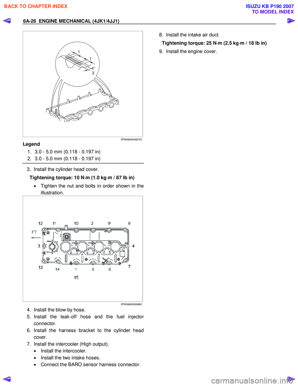
RTW 56ASH022701
Legend
1. 3.0 - 5.0 mm (0.118 - 0.197 in)
2. 3.0 - 5.0 mm (0.118 - 0.197 in)
3. Install the cylinder head cover.
Tightening torque: 10 N ⋅
⋅⋅
⋅
m (1.0 kg ⋅
⋅⋅
⋅
m / 87 lb in)
• Tighten the nut and bolts in order shown in the
illustration.
RTW 56ASH004801
4. Install the blow-by hose.
5. Install the leak-off hose and the fuel injecto
r
connector.
6. Install the harness bracket to the cylinder head cover.
7. Install the intercooler (High output). • Install the intercooler.
• Install the two intake hoses.
• Connect the BARO sensor harness connector.
8. Install the intake air duct.
Tightening torque: 25 N ⋅
⋅⋅
⋅
m (2.5 kg ⋅
⋅⋅
⋅
m / 18 lb in)
9. Install the engine cover.
BACK TO CHAPTER INDEX
TO MODEL INDEX
ISUZU KB P190 2007
Page 1389 of 6020

ENGINE MECHANICAL (4JK1/4JJ1) 6A-29
Removal
1. Remove the engine cover.
2. Disconnect the connectors. • Fuel Injector
• Throttle Assembly
• EGR Valve
• Glow Plug
• Barometric Sensor
• A/C Compressor Connector
3. Remove the A/C belt
4. Remove the A/C compressor.
5. Remove the A/C compressor bracket.
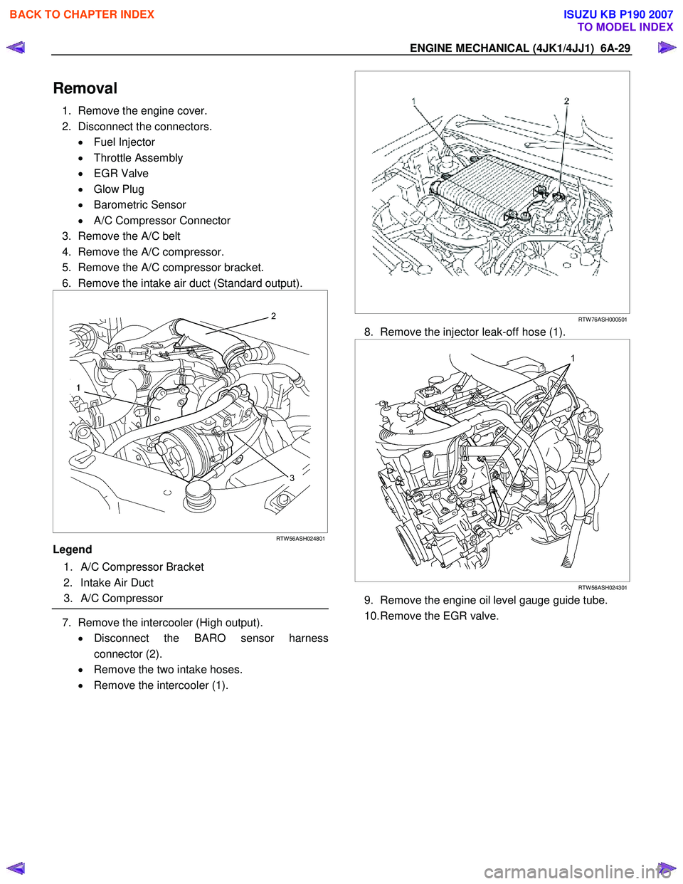
6. Remove the intake air duct (Standard output).
RTW 56ASH024801
Legend
1. A/C Compressor Bracket
2. Intake Air Duct
3. A/C Compressor
7. Remove the intercooler (High output).
• Disconnect the BARO sensor harness
connector (2).
• Remove the two intake hoses.
• Remove the intercooler (1).
RTW 76ASH000501
8. Remove the injector leak-off hose (1).
RTW 56ASH024301
9. Remove the engine oil level gauge guide tube.
10. Remove the EGR valve.
BACK TO CHAPTER INDEX
TO MODEL INDEX
ISUZU KB P190 2007
Page 1391 of 6020

ENGINE MECHANICAL (4JK1/4JJ1) 6A-31
Installation
1. Install the intake manifold gasket.
2. Install the intake manifold. • Tighten the nuts and bolts in the orde
r
described in the drawing.
Tightening torque: 25 N ⋅
⋅⋅
⋅
m (2.5 kg ⋅
⋅⋅
⋅
m / 18 lb ft)
RTW 56ASH018001
3. Install the throttle assembly and gasket.
• Tighten the bolts to the specified torque.
Tightening torque: 10 N ⋅
⋅⋅
⋅
m (1.0 kg ⋅
⋅⋅
⋅
m / 87 lb in)
4. Install the vacuum hose of swirl control valve.
5. Install the injection pipe (fuel rail - fuel injector). • It installs sequentially from No. 4 cylinder.
Tightening torque: 29 N ⋅
⋅⋅
⋅
m (3.0 kg ⋅
⋅⋅
⋅
m / 22 lb ft)
6. Install the EGR valve. • Tighten the nuts to the specified torque.
Tightening torque: 27 N ⋅
⋅⋅
⋅
m (2.8 kg ⋅
⋅⋅
⋅
m / 20 lb ft)
7. Install the engine oil level guide tube.
Tighten the nuts to the specified torque.
Tightening torque: 25 N ⋅
⋅⋅
⋅
m (2.5 kg ⋅
⋅⋅
⋅
m / 18 lb ft)
8. Install the intercooler (High output).
9. Connect the connector of other parts. • Fuel Injector
• Throttle Assembly
• EGR Valve
• Glow Plug
• Barometric Sensor
• A/C Compressor Connector
10. Install the leak-off hose.
RTW 56ASH024301
Legend
1. Injector Leek-off Hose
11. Install the intake air duct.
Tightening torque: 25 N ⋅
⋅⋅
⋅
m (2.5 kg ⋅
⋅⋅
⋅
m / 18 lb ft)
12.Install the A/C compressor bracket. Tightening torque: 25 N ⋅
⋅⋅
⋅
m (2.5 kg ⋅
⋅⋅
⋅
m / 18 lb ft)
13.Install the A/C compressor and A/C compresso
r
connector.
Tightening torque: 44 N ⋅
⋅⋅
⋅
m (4.5 kg ⋅
⋅⋅
⋅
m / 33 lb ft)
14.Install the A/C belt.
Check the A/C belt tension.
Depress the A/C belt mid-portion with 98 N (10 kg
/
22 lb) force.
Standard deflection: 7.6 - 9.2 mm (0.29 - 0.36 in)
RTW 510SH000201
15. Install the engine cover.
BACK TO CHAPTER INDEX
TO MODEL INDEX
ISUZU KB P190 2007