check engine ISUZU KB P190 2007 Workshop Repair Manual
[x] Cancel search | Manufacturer: ISUZU, Model Year: 2007, Model line: KB P190, Model: ISUZU KB P190 2007Pages: 6020, PDF Size: 70.23 MB
Page 1558 of 6020

FUEL SYSTEM (4JK1/4JJ1) 6C-17
Record the Fuel Injector ID Code Data from
each injector housing
1. Remove each fuel injector harness connector.
2. Record all numbers of each cylinder on the harness connector housing. The correct order fo
r
the fuel injector ID codes of the following
illustration is as follows:
5F 05 00 FB 00 F7 08 F5 19 FF 04 49
RTW 76ESH002601
Legend
1. Fuel Injector ID Code
2. Fuel Injector
Programming Fuel Injector ID Codes
1. Install a scan tool.
2. Turn ON the ignition, with the engine OFF.
3. Select Diagnostics > appropriate vehicle identification > 4JK1 or 4JJ1 > Programming >
Replace Injector.
4. In order to get programming approval, the on- screen displays a message to user. Get
programming approval from the TIS 2000 using
the following procedure:
a. Connect a scan tool to the terminal that installed TIS 2000 with the latest software and
the hardware key is plugged into port.
b. Turn ON the scan tool and keep at title screen.
c. Launch the TIS application.
d. Select the Security Access at the main screen.
e. Highlight the "Tech" 2 on the Diagnostic Tool Selection screen and click "Next".
f. Click "Close" on the Security Access Enabled screen.
g. Turn OFF the scan tool.
h. Disconnect the scan tool from the terminal.
5. Reinstall a scan tool to the vehicle.
6. Turn ON the ignition, with the engine OFF.
7. Select Diagnostics > appropriate vehicle identification > 4JK1 or 4JJ1 > Programming >
Replace Injector.
8. Enter 24 figures of replaced fuel injector ID code.
9.
After complete the programming, turn OFF the
ignition for 30 seconds.
10.Start the engine and let idle.
11.Inspect for a proper engine running condition and for no DTC's. Refer to the Diagnostic System
Check - Engine Controls if needed.
BACK TO CHAPTER INDEX
TO MODEL INDEX
ISUZU KB P190 2007
Page 1578 of 6020
FUEL SYSTEM (4JK1/4JJ1) 6C-37
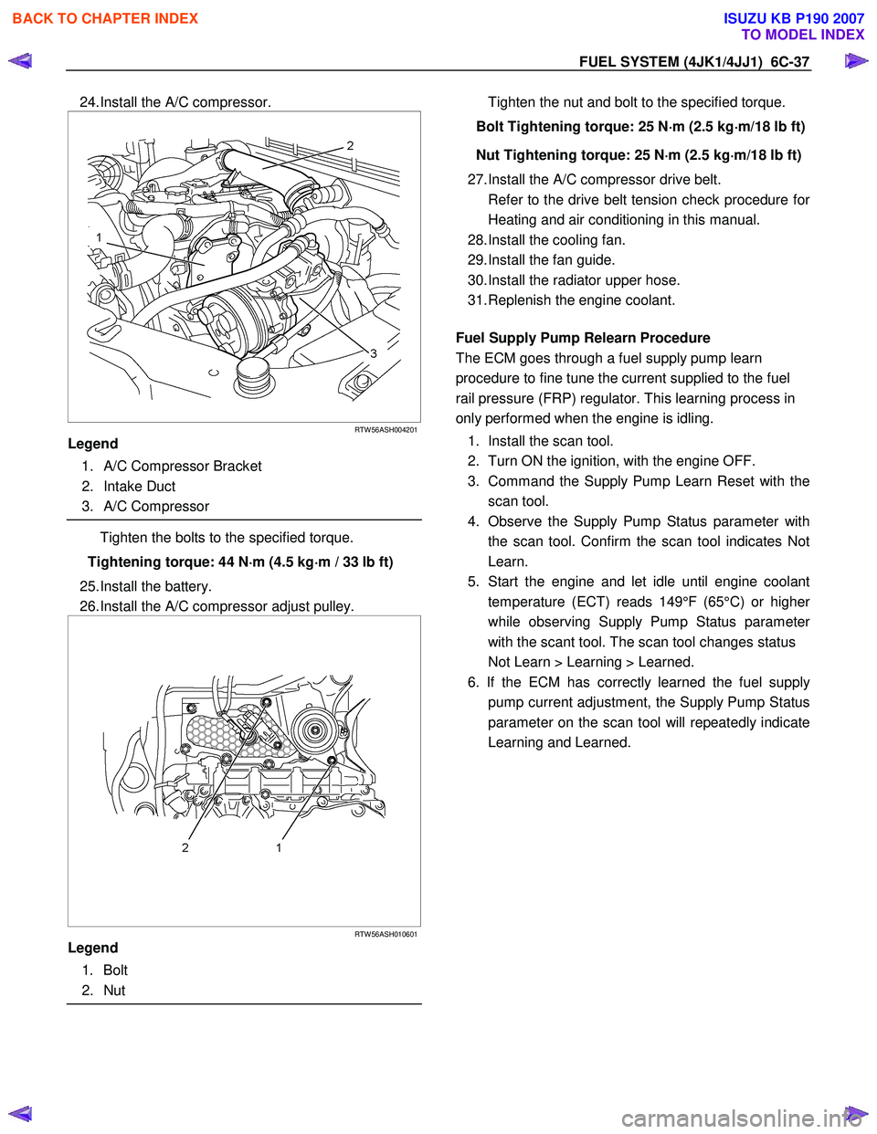
24. Install the A/C compressor.
RTW 56ASH004201
Legend
1. A/C Compressor Bracket
2. Intake Duct
3. A/C Compressor
Tighten the bolts to the specified torque.
Tightening torque: 44 N ⋅
⋅⋅
⋅
m (4.5 kg ⋅
⋅⋅
⋅
m / 33 lb ft)
25. Install the battery.
26. Install the A/C compressor adjust pulley.
RTW 56ASH010601
Legend
1. Bolt
2. Nut
Tighten the nut and bolt to the specified torque.
Bolt Tightening torque: 25 N ⋅
⋅⋅
⋅
m (2.5 kg ⋅
⋅⋅
⋅
m/18 lb ft)
Nut Tightening torque: 25 N ⋅
⋅⋅
⋅
m (2.5 kg ⋅
⋅⋅
⋅
m/18 lb ft)
27. Install the A/C compressor drive belt.
Refer to the drive belt tension check procedure fo
r
Heating and air conditioning in this manual.
28. Install the cooling fan.
29. Install the fan guide.
30. Install the radiator upper hose.
31. Replenish the engine coolant.
Fuel Supply Pump Relearn Procedure
The ECM goes through a fuel supply pump learn
procedure to fine tune the current supplied to the fuel
rail pressure (FRP) regulator. This learning process in
only performed when the engine is idling.
1. Install the scan tool.
2. Turn ON the ignition, with the engine OFF.
3. Command the Supply Pump Learn Reset with the scan tool.
4. Observe the Supply Pump Status parameter with the scan tool. Confirm the scan tool indicates Not
Learn.
5. Start the engine and let idle until engine coolant temperature (ECT) reads 149°F (65°C) or highe
r
while observing Supply Pump Status parameter
with the scant tool. The scan tool changes status
Not Learn > Learning > Learned.
6. If the ECM has correctly learned the fuel supply pump current adjustment, the Supply Pump Status
parameter on the scan tool will repeatedly indicate
Learning and Learned.
BACK TO CHAPTER INDEX
TO MODEL INDEX
ISUZU KB P190 2007
Page 1582 of 6020
FUEL SYSTEM (4JK1/4JJ1) 6C-41
Removal
Note: W hen repairs to the fuel system have been
completed, start the engine and check the fuel system
for loose connections or leakage. For the fuel system
diagnosis, see Section "Drivability and Emission".
1. Disconnect the battery ground cable.
2. Slowly loosen the fuel filler cap.
Note: Be careful that fuel does not spout out because o
f
change of pressure in the fuel tank.
Note: Cover opening of the filler neck to prevent an
y
dust entering. 3. Jack up the vehicle.
4. Disconnect the quick connector (5) of the fuel tube at the fuel cooler way.
5. Remove fuel return hose (8) from the pipe.
6. Remove fixing bolt (7) of the bracket fuel coole
r
and remove bracket fuel cooler (6).
Note: Cover the opening of the pipe to prevent any dust
and fuel leakage.
Note: For remove fuel cooler, Remove bolts (10) of the
fuel cooler and remove fuel cooler.
7. Support underneath of the fuel tank with a lifter.
8. Remove the inner liner of the wheel house at rea
r
left side.
9. Remove fixing bolt of the filler neck from the body.
10. Disconnect the quick connector (5) of the fuel tube from the fuel pipe and the evapo tube from evapo
joint connector.
Note: Cover the quick connector to prevent any dust
entering and prevent fuel leakage.
Note: Refer to "Fuel Tube/Quick Connector Fittings" in
this section when performing any repairs.
11. Remove fixing bolt (1) of the tank band and remove the tank band (2).
12. Disconnect the pump and sender connector on the fuel pump and remove the harness from the weld
clip on the fuel tank.
13. Lower the fuel tank (3).
Note: W hen lowering the fuel tank from the vehicle, do
not scratch the hoses and tubes by contact with othe
r
parts.
Installation
1. Raise the fuel tank.
Note: W hen raising the fuel tank to the vehicle, do not
scratch the hoses and tubes by contact with other parts.
2. Connect the pump and sender connector to the fuel pump and install the harness to the weld clip
on the tank.
Note: The connector must be securely connected
against the stopper.
3. Install the tank band and fasten bolt.
Torque: 68 N ⋅
⋅⋅
⋅
m (6.9 kg ⋅
⋅⋅
⋅
m /50 lb ft)
Note: The anchor of the tank band must be securely
installed to the guide hole on the frame.
4. Connect the quick connector of the fuel tube to the fuel pipe and the evapo tube from evapo joint
connector.
Note: Pull off the left checker on the fuel pipe.
Note: Refer to "Fuel Tube/Quick Connector Fittings" in
this section when performing any repairs.
5. Install the filler neck to the body with bolt.
Note: For install the fuel cooler to the bracket with bolt.
Torque: 6.5 N ⋅
⋅⋅
⋅
m (0.7 kg ⋅
⋅⋅
⋅
m /61 lb in)
6. Install the bracket to Frame with bolt. Torque: 48 N ⋅
⋅⋅
⋅
m (4.9 kg ⋅
⋅⋅
⋅
m /35 lb ft)
7. Install the fuel return hose at the fuel cooler way.
8. Install the quick connector at the fuel cooler way.
9. Install the inner liner of the wheel house at rear left side.
10. Remove lifter from the fuel tank.
11. Lower the vehicle.
12. Tighten the filler cap until at least three clicks.
13. Connect the battery ground cable.
BACK TO CHAPTER INDEX
TO MODEL INDEX
ISUZU KB P190 2007
Page 1584 of 6020
FUEL SYSTEM (4JK1/4JJ1) 6C-43
Removal
Note: W hen repairs to the fuel system have been
completed, start the engine and check the fuel system
for loose connections or leakage. For the fuel system
diagnosis, see Section "Drivability and Emission".
1. Remove the fuel tank assembly (8). Refer to "Fuel Tank Removal" in this section.
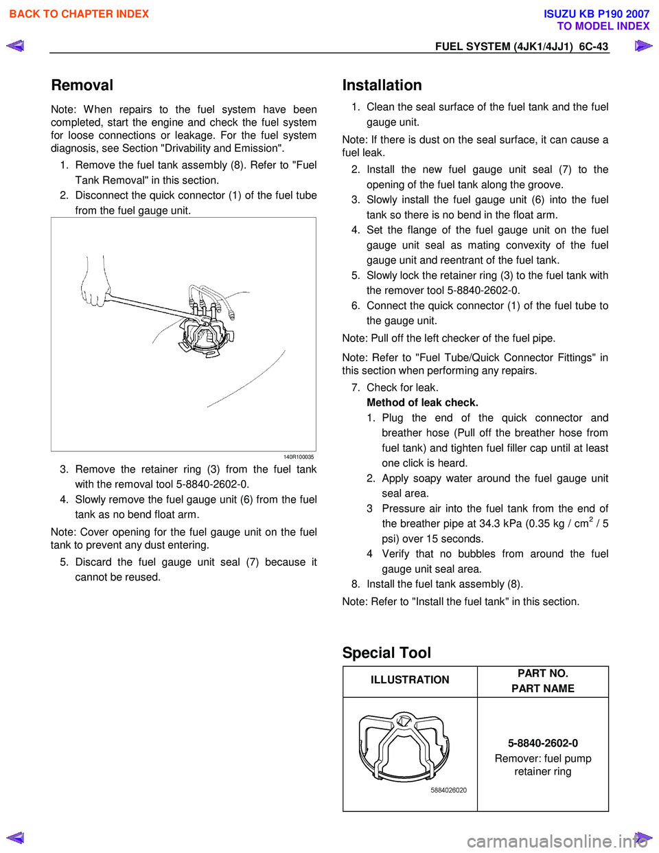
2. Disconnect the quick connector (1) of the fuel tube from the fuel gauge unit.
140R100035
3. Remove the retainer ring (3) from the fuel tank
with the removal tool 5-8840-2602-0.
4. Slowly remove the fuel gauge unit (6) from the fuel tank as no bend float arm.
Note: Cover opening for the fuel gauge unit on the fuel
tank to prevent any dust entering.
5. Discard the fuel gauge unit seal (7) because it cannot be reused.
Installation
1. Clean the seal surface of the fuel tank and the fuel
gauge unit.
Note: If there is dust on the seal surface, it can cause a
fuel leak.
2. Install the new fuel gauge unit seal (7) to the opening of the fuel tank along the groove.
3. Slowly install the fuel gauge unit (6) into the fuel tank so there is no bend in the float arm.
4. Set the flange of the fuel gauge unit on the fuel gauge unit seal as mating convexity of the fuel
gauge unit and reentrant of the fuel tank.
5. Slowly lock the retainer ring (3) to the fuel tank with the remover tool 5-8840-2602-0.
6. Connect the quick connector (1) of the fuel tube to the gauge unit.
Note: Pull off the left checker of the fuel pipe.
Note: Refer to "Fuel Tube/Quick Connector Fittings" in
this section when performing any repairs.
7. Check for leak. Method of leak check.
1. Plug the end of the quick connector and breather hose (Pull off the breather hose from
fuel tank) and tighten fuel filler cap until at least
one click is heard.
2. Apply soapy water around the fuel gauge unit seal area.
3 Pressure air into the fuel tank from the end o
f
the breather pipe at 34.3 kPa (0.35 kg / cm2 / 5
psi) over 15 seconds.
4 Verify that no bubbles from around the fuel gauge unit seal area.
8. Install the fuel tank assembly (8).
Note: Refer to "Install the fuel tank" in this section.
Special Tool
ILLUSTRATION PART NO.
PART NAME
5-8840-2602-0
Remover: fuel pump retainer ring
BACK TO CHAPTER INDEX
TO MODEL INDEX
ISUZU KB P190 2007
Page 1586 of 6020

FUEL SYSTEM (4JK1/4JJ1) 6C-45
Note: Do not use tools of any kind. Only use bare hands
when disconnecting the connector. Use a lubricant (light
oil) and/or push and pull the connector until the pipe is
disconnected.
140R100037
Cover the connectors that were removed with a plastic
bag, to prevent dust or rain water from entering.
140R100028
Reuse of Quick-Connector
•
Replace the port and connector if a scratch, dent
or crack is found.
• Remove any dirt build up on the port when
installing the connector. Replace the connector, i
f
there is any rust, dents or scratches.
• After cleaning the port, insert it straight into the
connector until it clicks. After it clicks, try pulling it
out at 49 N (5 kg / 11 lb) to make sure that it is not
drawn and is securely locked.
140R100036
Assembling Advice
By applying engine oil or light oil to the pipe, port makes
pipe assembly easier. The pipe assembly should take
place immediately after applying oil (to prevent dust
from sticking to the pipe surface - which may decrease
sealing ability).
Test/Inspection After Assembling
1. Reconnect the battery negative cable.
2. Start the engine and observe the engine idle speed. The presence of dirt in the fuel system ma
y
affect the fuel injection system.
3. Check for fuel leakage from the connector.
BACK TO CHAPTER INDEX
TO MODEL INDEX
ISUZU KB P190 2007
Page 1589 of 6020
ENGINE ELECTRICAL (4JK1/4JJ1) 6D-1
SECTION 6D
ENGINE ELECTRICAL
TABLE OF CONTENTS
Charging System ................................................ 6D-2
Servicing Cautions .......................................... 6D-2
Important Generator Components and
Function.......................................................... 6D-2
Troubleshooting .............................................. 6D-5
Diagnosis......................................................... 6D-7
Specifications .................................................. 6D-8
Unit Se rv ic ing (4 JJ 1) ....................................... .... ..6D -9
Disassembly .................................................... 6D-10
Inspection and Repair ..................................... 6D-11 Rotor Assembly ........................................... 6D-11
Stator Coil .................................................... 6D-12
Brushes ....................................................... 6D-12
Rectifier ....................................................... 6D-13
Regulator Assembly..................................... 6D-13
Measuring Procedure .................................. 6D-13
Reassembly..................................................... 6D-14
Final Assembly ................................................ 6D-14
Starter Motor ...................................................... 6D-15 Starting Circuit Diagram .................................. 6D-15
Removal and Installation ................................. 6D-15 Important Operations – Removal................. 6D-15
Important Operations – Installation.............. 6D-15
Disassembly .................................................... 6D-16 Disassembly Steps ...................................... 6D-16
Important Operations ................................... 6D-17
Inspection and Repair ..................................... 6D-20 Armature ...................................................... 6D-20
Yoke............................................................. 6D-21
Brush and Brush Holder .............................. 6D-22
Overrunning Clutch...................................... 6D-22
Bearing ........................................................ 6D-23
Reassembly..................................................... 6D-24 Reassembly Steps ....................................... 6D-24
Important Operations ................................... 6D-25
Inspection After Assembly ........................... 6D-26
Magnetic Switch .............................................. 6D-27
Torque Specifications...................................... 6D-28
Pre-Heating System ........................................... 6D-29 Inspection and Repair ..................................... 6D-29 Visual Check................................................ 6D-29
Glow Relay .................................................. 6D-29
Glow Plug .................................................... 6D-29
BACK TO CHAPTER INDEX
TO MODEL INDEX
ISUZU KB P190 2007
Page 1590 of 6020
6D-2 ENGINE ELECTRICAL (4JK1/4JJ1)
Charging System
Servicing Cautions
• Battery polarity is important. If the battery cables
are reversed, the generator diodes will be
destroyed.
• Do not remove the battery cables or the charging
circuit wiring when the engine is running.
• Confirm that the terminal wires are connected to
the proper terminals by checking the terminal
numbers (the number on the terminal wire and the
terminal must be the same).
• Disconnect the battery negative cable (-) before
inspecting the generator.
• Do not open or close the battery relay switch when
the engine is running.
• Disconnect the battery negative cable (-) when
using external equipment (Quick-Charge) to
charge the battery.
• W hen steam cleaning or washing the engine, do
not allow steam or water to come in direct contact
with the battery and other electrical system
components.
• Be sure to read the item on belt tension
adjustment before beginning the procedure.
Important Generator Components
and Function
• The generator used on 4JK1 engine cannot be
disassembled.
• The generator uses a built-in solid-state IC voltage
regulator. The regulator and other important
components together with their connections are
shown in the illustration.
• The voltage regulator is installed to the rear cove
r
assembly of the generator together with the brush
holder and the rectifier. The generator requires no
additional voltage regulation.
• 9 diodes are connected to the stator coil to convert
AC to DC. The DC voltage is delivered to the
generator output terminal.
BACK TO CHAPTER INDEX
TO MODEL INDEX
ISUZU KB P190 2007
Page 1595 of 6020

ENGINE ELECTRICAL (4JK1/4JJ1) 6D-7
Diagnosis
On-vehicle Inspection
The charging system warning light tells the vehicle
operator of possible problems with the system.
W hen the ignition switch is moved to the ON position,
the light turns on. The light turns off immediately afte
r
the engine is started. If the light turns on during engine
operation, there is a problem with the charging system.
Perform the checks described below.
1. Check the belt (broken or loose).
2. Check the harness connectors (loose o
r
disconnected).
3. W ith the engine off, turn the ignition switch to the ON position. If the warning lamp does not light,
remove the harness connector from the generator.
Ground the connector IG terminal. The lamp
should light. If it does not, the bulb is burned out.
Replace the bulb.
4. Start the engine. If the warning lamp remains on, the generator must be repaired or replaced.
BACK TO CHAPTER INDEX
TO MODEL INDEX
ISUZU KB P190 2007
Page 1599 of 6020

ENGINE ELECTRICAL (4JK1/4JJ1) 6D-11
13.Remove the stator.
066RS030
14.Remove the bolts securing the regulator, the
rectifier, and the brush holder. Separate the parts.
066RW 025
Inspection and Repair
Repair or replace any parts found to be excessively
worn or damaged during the inspection procedure.
Rotor Assembly
1. Check for dirty or rough slip ring surfaces. Remove
dirt from the surfaces with a clean rag. Use No.
500 or No. 600 sandpaper to smooth the surfaces.
2. Measure the slip ring diameters. Replace the slip ring if the diameter is less than the specified limit.
Slip ring diameter mm (in)
Standard 27 (1.063)
Limit 26 (1.024)
066RS032
3. Measure the electrical resistance between the slip
rings. If the resistance is greater than the specified
limit (open circuit), repair is required.
Slip ring resistance Ω
Less than 3.75
066RS033
BACK TO CHAPTER INDEX
TO MODEL INDEX
ISUZU KB P190 2007
Page 1600 of 6020

6D-12 ENGINE ELECTRICAL (4JK1/4JJ1)
4. Check for conductivity between the slip rings and
the rotor core. If there is continuity, the roto
r
assembly must be replaced.
066RS017
Stator Coil
1. Measure the stator coil resistance. If the
resistance is less than the specified value, the
stator coil must be replaced.
Stator coil resistance
0.07Ω at 20 °C (68 °F)
066RS034
2. Measure the resistance between the stator coil
and the stator core. If the resistance is less than
the specified value, the stator coil must be
replaced.
Stator coil/core resistance MΩ
1
066RS035
Brushes
Measure the brush height. If the height is less than the
specified limit, the brushes must be replaced.
Brush height mm (in)
Standard 18 (0.709)
Limit 5.5 (0.217)
066RW 024
BACK TO CHAPTER INDEX
TO MODEL INDEX
ISUZU KB P190 2007