engine coolant ISUZU KB P190 2007 Workshop Repair Manual
[x] Cancel search | Manufacturer: ISUZU, Model Year: 2007, Model line: KB P190, Model: ISUZU KB P190 2007Pages: 6020, PDF Size: 70.23 MB
Page 2646 of 6020

Engine Mechanical – V6 Page 6A1–167
Inspect
Visual Inspection
1 Inspect the cylinder head (1) camshaft bearing
surfaces for the following conditions:
• excessive scoring or pitting,
• discoloration from overheating, and
• deformation from excessive wear.
2 If any of the above conditions exist on the camshaft bearing surfaces, replace the cylinder head. Do not
machine the camshaft bearing journals.
Figure 6A1 – 287
3 Inspect the cylinder head for the following: • Cracks, damage or pitting in the combustion chambers.
• Debris in the oil galleries. continue to clean the galleries until all debris is removed.
• Coolant leaks or damage to the deck face sealing surface. if coolant leaks are present, measure the surface
warpage as described under Cylinder Head Measurement within this Section.
• Burrs or any defects that would degrade the sealing of a new secondary camshaft chain tensioner gasket.
• Damage to any gasket surfaces.
• Damage to any threaded bolt holes.
• Burnt or eroded areas in the combustion chamber.
• Cracks in the exhaust ports and combustion chambers.
• External cracks in the water passages.
• Restrictions in the intake or exhaust passages.
• Restrictions in the cooling system passages.
• Rusted, damaged or leaking core plugs.
4 If the cylinder head is cracked or damaged, it must be replaced. No welding or patching of the cylinder head is recommended.
Cylinder Head Measurement
NOTE
For all cylinder head and associated component
specifications, refer to 5 Specifications.
Camshaft Journal Clearance
1 Install the camshaft bearing cap in the cylinder head without the camshaft.
2 Install the camshaft cap bolts and tighten to the correct torque specification
Camshaft bearing cap attaching bolt........8.0 – 12.0 Nm.
3 Measure the camshaft bearings using an inside micrometer.
4 Subtract the camshaft journal diameter from the camshaft bearing diameter. This will provide the running clearance. If the running clearance exceeds specifications and the camshaft journals are within specification, replace the
cylinder head.
Camshaft Journal Alignment
1 Ensure the camshafts are serviceable, refer to 3.19 Camshaft for measuring procedures.
BACK TO CHAPTER INDEX
TO MODEL INDEX
ISUZU KB P190 2007
Page 2653 of 6020

Engine Mechanical – V6 Page 6A1–174
Valve Stem Height Measurement Procedure
CAUTION
To determine the valve stem height
measurement, measure from the valve
spring seat to the valve spring retainer.
1 Install the valve into the valve guide.
2 Ensure the valve is seated to the valve seat.
3 Install the valve stem oil seal.
4 Install the valve spring retainer and valve stem keys.
5 Measure the distance (1) between the cylinder head to the bottom of the valve spring retainer, refer to 5
Specifications.
6 If the maximum height specification is exceeded, a new valve should be installed and the valve stem
height re-measured.
Figure 6A1 – 297
CAUTION
Do not grind the valve stem tip. The tip of the
valve is hardened and grinding the tip will
eliminate the hardened surface causing
premature wear and possible engine damage.
CAUTION
Do not use shims to adjust valve stem height.
The use of shims will cause the valve spring
to bottom out before the camshaft lobe is at
peak lift and engine damage could result.
7 If the valve stem height still exceeds the maximum height specification, the cylinder head must be replaced.
Assemble
1 Install the cylinder head coolant threaded plugs (1) and tighten to the correct torque specification.
Cylinder head threaded plug ..............................31.0 Nm
Figure 6A1 – 298
BACK TO CHAPTER INDEX
TO MODEL INDEX
ISUZU KB P190 2007
Page 2664 of 6020

Engine Mechanical – V6 Page 6A1–185
Remove
1 Remove the skid plate.
2 Drain the radiator coolant, refer to 6B1 Engine Cooling – V6.
3 Disconnect the battery negative and positive terminal, refer to 8A Electrical Body & Chassis.
4 Remove the battery from the vehicle.
5 Depressurise the fuel system pressure, refer to 6C Fuel System – V6.
6 Make alignment marks on the bonnet and hinges in order to return the bonnet to the exact original position.
7 Remove the bonnet, refer to 2B Sheet Metal.
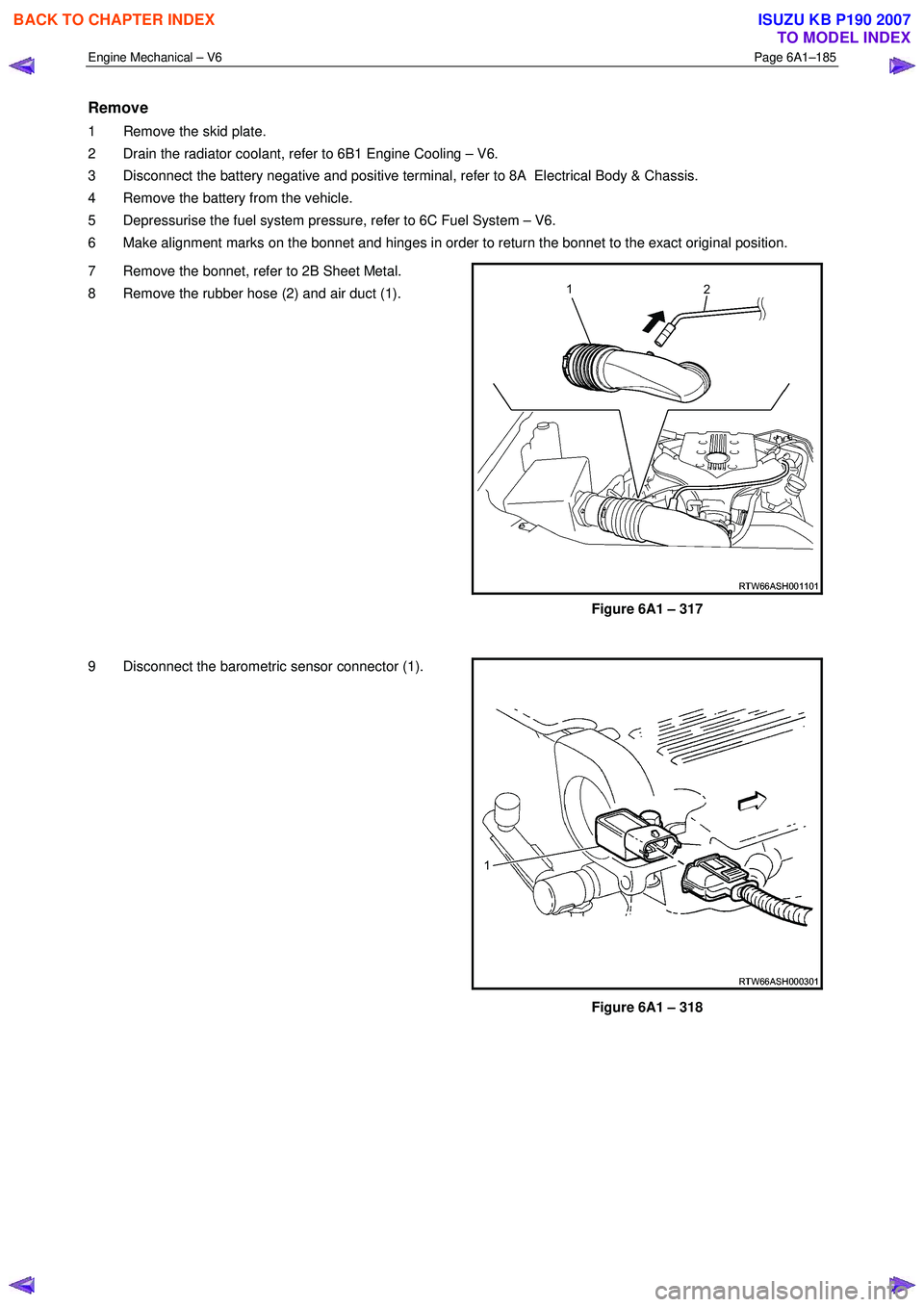
8 Remove the rubber hose (2) and air duct (1).
Figure 6A1 – 317
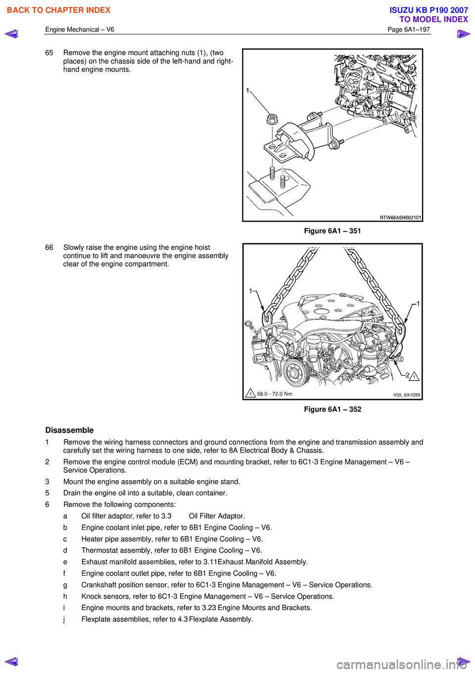
9 Disconnect the barometric sensor connector (1).
Figure 6A1 – 318
BACK TO CHAPTER INDEX
TO MODEL INDEX
ISUZU KB P190 2007
Page 2673 of 6020

Engine Mechanical – V6 Page 6A1–194
54 Remove the power steering pump bracket mounting
bolts (three places) then remove the pump bracket
(1).
Figure 6A1 – 342
55 Release the lower radiator hose clamp (1) and remove the lower hose from the coolant pipe (2).
Figure 6A1 – 343
56 Release the upper radiator hose clamp (1) and remove the upper hose from the coolant pipe (2).
Figure 6A1 – 344
BACK TO CHAPTER INDEX
TO MODEL INDEX
ISUZU KB P190 2007
Page 2676 of 6020

Engine Mechanical – V6 Page 6A1–197
65 Remove the engine mount attaching nuts (1), (two
places) on the chassis side of the left-hand and right-
hand engine mounts.
Figure 6A1 – 351
66 Slowly raise the engine using the engine hoist continue to lift and manoeuvre the engine assembly
clear of the engine compartment.
Figure 6A1 – 352
Disassemble
1 Remove the wiring harness connectors and ground connections from the engine and transmission assembly and carefully set the wiring harness to one side, refer to 8A Electrical Body & Chassis.
2 Remove the engine control module (ECM) and mounting bracket, refer to 6C1-3 Engine Management – V6 – Service Operations.
3 Mount the engine assembly on a suitable engine stand.
5 Drain the engine oil into a suitable, clean container.
6 Remove the following components: a Oil filter adaptor, refer to 3.3 Oil Filter Adaptor.
b Engine coolant inlet pipe, refer to 6B1 Engine Cooling – V6.
c Heater pipe assembly, refer to 6B1 Engine Cooling – V6.
d Thermostat assembly, refer to 6B1 Engine Cooling – V6.
e Exhaust manifold assemblies, refer to 3.11Exhaust Manifold Assembly.
f Engine coolant outlet pipe, refer to 6B1 Engine Cooling – V6.
g Crankshaft position sensor, refer to 6C1-3 Engine Management – V6 – Service Operations.
h Knock sensors, refer to 6C1-3 Engine Management – V6 – Service Operations.
i Engine mounts and brackets, refer to 3.23 Engine Mounts and Brackets.
j Flexplate assemblies, refer to 4.3 Flexplate Assembly.
BACK TO CHAPTER INDEX
TO MODEL INDEX
ISUZU KB P190 2007
Page 2677 of 6020

Engine Mechanical – V6 Page 6A1–198
k Timing chains, tensioners, shoes, guides & sprockets, refer to 3.16 Timing Chains, Tensioners, Shoes and
Guides.
l Cylinder head assemblies, refer to 3.22 Cylinder Head Assembly.
m Oil pan assembly, refer to 4.2 Oil Pan and Oil Pump Suction Pipe Assembly.
n Piston and connecting rod assemblies, refer to 4.5 Pistons, Pins, Rings, Connecting Rods and Big-end Bearings.
o Crankshaft assembly, refer to 4.6 Crankshaft and Main Bearings.
p Piston oil nozzles, refer 4.5 Pistons, Pins, Rings, Connecting Rods and Big-end Bearings.
Reassemble
Reassembly of the engine assembly is the reverse of the disassembly procedure.
Reinstall
Reinstallation of the engine assembly is the reverse to the removal procedure, noting the following:
NOTE
Refer to 6 Torque Wrench Specifications
for the correct torque specifications.
1 Tighten the fasteners to the correct torque specification.
Engine ground connector bolt
torque specification ............................................10.0 Nm
Power steering high pressure line
attaching bolt torque specification .............8.0 – 12.0 Nm
Power steering high pressure line
flare nut torque specification ...................25.0 – 35.0 Nm
Engine mount to frame attaching bolt
torque specification .................................44.0 – 60.0 Nm
Knock Sensor Attaching Nut
torque specification ............................................23.0 Nm
2 Use only the specified engine lubricant type and quantity. It is recommended that a fluorescent oil dye, such as that contained in J 28481-B, be added to assist in any future oil leak diagnosis.
3 Fill the cooling system with the correct quantity and grade of coolant, refer to 6B1 Engine Cooling – V6.
4 Check transmission fluid level, replenishing as required, using the specified lubricant for the transmission fitted, refer to 7C1 Automatic – 4L60E – General Information.
5 Disable the ignition system, refer to 6C1-3 Engine Management – V6 – Service Operations.
6 Crank the engine several times. Listen for any unusual noises or evidence that parts are binding.
7 Enable the ignition system. Start the engine and listen for any unusual noises.
8 Check the vehicle oil pressure gauge or warning indicator and confirm the engine has acceptable oil pressure. If required, install an oil pressure gauge and measure the engine oil pressure, refer to 2.19 Engine Oil Pressure
Diagnosis.
9 Run the engine at about 1,000 r.p.m. until the engine has reached normal operating temperature.
10 Listen for any unusual noises.
11 Check for oil, fuel, coolant and exhaust leaks while the engine is running, correcting as required.
12 Perform a final inspection for correct engine oil and coolant levels.
4.2 Oil Pan and Oil Pump Suction Pipe Assembly
Remove
1 Remove the engine assembly from the vehicle, refer to 4.1 Engine .
2 Separate the engine and transmission assemblies, refer to 7C1 Automatic – 4L60E – General Information.
3 Mount the engine assembly on a suitable engine stand.
4 Remove the engine front cover, refer to 3.15 Front Cover Assembly.
BACK TO CHAPTER INDEX
TO MODEL INDEX
ISUZU KB P190 2007
Page 2715 of 6020

Engine Mechanical – V6 Page 6A1–236
5 Remove the right-hand side M14 coolant drain
threaded plug (1).
Figure 6A1 – 440
6 Remove the rear M14 oil gallery threaded plug (1).
Figure 6A1 – 441
7 Remove the left-hand side M14 coolant drain threaded plug (1).
Figure 6A1 – 442
BACK TO CHAPTER INDEX
TO MODEL INDEX
ISUZU KB P190 2007
Page 2716 of 6020

Engine Mechanical – V6 Page 6A1–237
8 Remove the left-hand side M20 oil gallery threaded
plug (1).
Figure 6A1 – 443
CAUTION
Do not force coolant expansion plugs
downwards during removal procedure as the
cylinder block will be damaged.
9 Remove the coolant expansion plugs (1).
Figure 6A1 – 444
10 Remove the cylinder block-to-transmission alignment dowels (1).
Figure 6A1 – 445
BACK TO CHAPTER INDEX
TO MODEL INDEX
ISUZU KB P190 2007
Page 2720 of 6020

Engine Mechanical – V6 Page 6A1–241
2 Install a new front oil gallery expansion plug (1).
Figure 6A1 – 451
3 Install the cylinder block-to-transmission alignment dowels (1).
Figure 6A1 – 452
4 Place RTV sealant on new coolant expansion plugs (1) and install the new coolant expansion plugs.
Figure 6A1 – 453
BACK TO CHAPTER INDEX
TO MODEL INDEX
ISUZU KB P190 2007
Page 2721 of 6020

Engine Mechanical – V6 Page 6A1–242
5 Install the left-hand side M20 oil gallery threaded plug
(1) and tighten to the correct torque specification.
Left-hand side M20 cylinder block
oil gallery threaded plug
torque specification .................................27.0 – 35.0 Nm
Figure 6A1 – 454
6 Install the left-hand side M14 coolant drain threaded plug (1) and tighten to the correct torque specification.
Left-hand side M14 cylinder block
coolant drain threaded plug
torque specification .................................27.0 – 35.0 Nm
Figure 6A1 – 455
7 Install the M14 rear oil gallery threaded plug (1) and tighten to the correct torque specification.
M14 cylinder block rear oil gallery
threaded plug torque specification ..........27.0 – 35.0 Nm
Figure 6A1 – 456
BACK TO CHAPTER INDEX
TO MODEL INDEX
ISUZU KB P190 2007