engine coolant ISUZU KB P190 2007 Workshop Repair Manual
[x] Cancel search | Manufacturer: ISUZU, Model Year: 2007, Model line: KB P190, Model: ISUZU KB P190 2007Pages: 6020, PDF Size: 70.23 MB
Page 2410 of 6020

6E–240 ENGINE DRIVEABILITY AND EMISSIONS
7 1. Using a Tech 2, display the engine coolanttemperature and note the value.
2. Check the resistance of the engine coolant temperature sensor.
Is the actual resistance near the resistance value in
the chart for the temperature that was noted?
—Go to Step 8Replace the
ECT sensor. Verify repair
8 1. Using a Tech 2, display the MAP sensor value in comparison with atmosphere temperature.
2. Check for a faulty, plugged, or incorrectly installed MAP sensor.
Was the problem found? — Verify repair Go to Step 9
9 Using Tech 2, monitor throttle position with the engine idling.
Is the throttle position at the specified value and
steady?
0% Go to Step 10Refer to
Diagnostic
Trouble Code P0123 for further
diagnosis
10 Check for proper ignition voltage output with the spark tester.
Was a problem found? — Verify repair Go to Step 11
11 1. Remove the spark plugs and check for gas or oil fouling cracks, wear, improper gap, burned
electrodes, heavy deposits, or improper heat
range.
2. If spark plugs are fouled, the cause of fouling must be determined before replacing the spark plugs.
Was a problem found? — Verify repair Go to Step 12
12 Check for a loose ignition control module ground. Was a problem found? — Verify repair Go to Step 13
13 Check items that can cause the engine to run rich. Refer to DTC P1167 “Fuel Supply System Rich During
Deceleration Fuel Cut Off”.
Was a problem found? — Verify repair Go to Step 14
14 Check items that can cause the engine to run lean. Refer to DTC P1171 “Fuel Supply System Lean
During Power Enrichment”.
Was a problem found? — Verify repair Go to Step 15
15 Check the injector connectors, if any of the injectors are connected any incorrect cylinder, correct as
necessary.
Was a problem found? — Verify repair Go to Step 16
16 1. Check for faulty engine mounts. 2. If a problem is found, repair as necessary.
Was a problem found? — Verify repair Go to Step 17
Step
Action Value(s) Yes No
Temperature (°C) Resistance (Ω) (Approximately)
-20 26740
0 9120
20 3500
40 1464
60 664
80 333
100 175
120 102
BACK TO CHAPTER INDEX
TO MODEL INDEX
ISUZU KB P190 2007
Page 2424 of 6020

6E–254 ENGINE DRIVEABILITY AND EMISSIONS
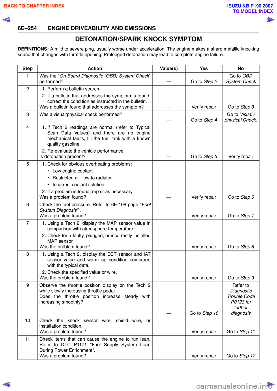
DETONATION/SPARK KNOCK SYMPTOM
DEFINITIONS: A mild to severe ping, usually worse under acceleration. The engine makes a sharp metallic knocking
sound that changes with throttle opening. Prolonged detonation may lead to complete engine tailure.
Step Action Value(s) Yes No
1 Was the “ On-Board Diagnostic (OBD) System Check ”
performed? — Go to Step 2Go to
OBD
System Check
2 1. Perform a bulletin search. 2. If a bulletin that addresses the symptom is found,correct the condition as instructed in the bulletin.
Was a bulletin found that addresses the symptom? — Verify repair Go to Step 3
3 Was a visual/physical check performed? —Go to Step 4Go to
Visual /
physical Check .
4 1. If Tech 2 readings are normal (refer to Typical Scan Data Values) and there are no engine
mechanical faults, fill the fuel tank with a known
quality gasoline.
2. Re-evaluate the vehicle performance.
Is detonation present? — Go to Step 5Verify repair
5 1. Check for obvious overheating problems: • Low engine coolant
• Restricted air flow to radiator
• Incorrect coolant solution
2. If a problem is found, repair as necessary.
Was a problem found? — Verify repair Go to Step 6
6 Check the fuel pressure. Refer to 6E-108 page “ Fuel
System Diagnosis” .
Was a problem found? — Verify repair Go to Step 7
7 1. Using a Tech 2, display the MAP sensor value in comparison with atmosphere temperature.
2. Check for a faulty, plugged, or incorrectly installed MAP sensor.
Was the problem found? — Verify repair Go to Step 8
8 1. Using a Tech 2, display the ECT sensor and IAT sensor value and warm up condition compared
with the typical data.
2. Check the specified value or wire.
Was the problem found? — Verify repair Go to Step 9
9 Observe the throttle position display on the Tech 2 while slowly increasing throttle pedal.
Does the throttle position increase steady with
increasing smoothly?
—Go to Step 10Refer to
Diagnostic
Trouble Code P0123 for further
diagnosis
10 Check the knock sensor wire, shield wire, or installation condition.
Was a problem found? — Verify repair Go to Step 11
11 Check items that can cause the engine to run lean. Refer to DTC P1171 “Fuel Supply System Lean
During Power Enrichment”.
Was a problem found? — Verify repair Go to Step 12
BACK TO CHAPTER INDEX
TO MODEL INDEX
ISUZU KB P190 2007
Page 2426 of 6020

6E–256 ENGINE DRIVEABILITY AND EMISSIONS
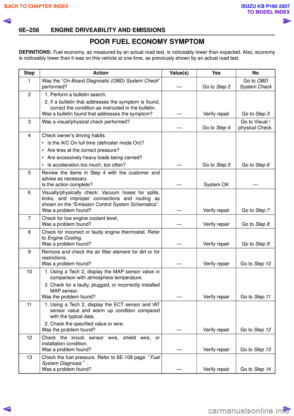
POOR FUEL ECONOMY SYMPTOM
DEFINITIONS: Fuel economy, as measured by an actual road test, is noticeably lower than expected. Also, economy
is noticeably lower than it was on this vehicle at one time, as previously shown by an actual road test.
Step Action Value(s) Yes No
1 Was the “ On-Board Diagnostic (OBD) System Check ”
performed? — Go to Step 2Go to
OBD
System Check
2 1. Perform a bulletin search. 2. If a bulletin that addresses the symptom is found,correct the condition as instructed in the bulletin.
Was a bulletin found that addresses the symptom? — Verify repair Go to Step 3
3 Was a visual/physical check performed? —Go to Step 4Go to Visual /
physical Check.
4 Check owner’s driving habits. • Is the A/C On full time (defroster mode On)?
• Are tires at the correct pressure?
• Are excessively heavy loads being carried?
• Is acceleration too much, too often? — Go to Step 5Go to Step 6
5 Review the items in Step 4 with the customer and advise as necessary.
Is the action complete? — System OK —
6 Visually/physically check: Vacuum hoses for splits, kinks, and improper connections and routing as
shown on the “Emission Control System Schematics”.
Was a problem found? — Verify repair Go to Step 7
7 Check for low engine coolant level. Was a problem found? — Verify repair Go to Step 8
8 Check for incorrect or faulty engine thermostat. Refer to Engine Cooling .
Was a problem found? — Verify repair Go to Step 9
9 Remove and check the air filter element for dirt or for restrictions.
Was a problem found? — Verify repair Go to Step 10
10 1. Using a Tech 2, display the MAP sensor value in comparison with atmosphere temperature.
2. Check for a faulty, plugged, or incorrectly installed MAP sensor.
Was the problem found? — Verify repair Go to Step 11
11 1. Using a Tech 2, display the ECT sensor and IAT sensor value and warm up condition compared
with the typical data.
2. Check the specified value or wire.
Was the problem found? — Verify repair Go to Step 12
12 Check the knock sensor wire, shield wire, or installation condition.
Was a problem found? — Verify repair Go to Step 13
13 Check the fuel pressure. Refer to 6E-108 page “Fuel
System Diagnosis
” .
Was a problem found? — Verify repair Go to Step 14
BACK TO CHAPTER INDEX
TO MODEL INDEX
ISUZU KB P190 2007
Page 2435 of 6020

ENGINE DRIVEABILITY AND EMISSIONS 6E–265
ENGINE COOLANT TEMPERATURE (ECT)
SENSOR
Location
Installed to the thermostat housing.
Removal Procedure 1. Disconnect the negative battery cable.
2. Drain enough engine coolant so that the coolant level will be below the ECT sensor.
3. Disconnect connector from the ECT sensor.
4. Loosen and remove the ECT sensor from the thermostat housing.
NOTE: Cool down the engine before above procedures
are carried out.
Installation Procedure
1. Apply sealer to threads of screw at the ECT sensor.
2. Tighten the ECT sensor with specified tightening torque.
Tightening Torque
• Bolt: 13N·m (1.3kgf·m)
3. Connect a ECT sensor connector to the ECT sensor.
4. Fill the engine coolant.
5. Connect the negative battery cable.
NOTE: Verify any DTCs (diagnosis Trouble Code) are
not stored after replacement.
Verify no engine coolant leaking from the sensor
threads after replacement.
INTAKE AIR TEMPERATURE (IAT) SENSOR
Location
Installed to the intake duct housing.
Removal Procedure 1. Disconnect the negative battery cable.
2. Disconnect a IAT sensor connector from the IAT sensor.
3. Remove the IAT sensor from the intake duct.
Installation Procedure 1. Install the IAT sensor into intake air duct.
2. Connect a IAT sensor connector to the IAT sensor.
3. Connect the negative battery cable.
NOTE: Verify any DTCs (diagnosis Trouble Code) are
not stored after replacement.
BACK TO CHAPTER INDEX
TO MODEL INDEX
ISUZU KB P190 2007
Page 2481 of 6020

Engine Mechanical – V6 Page 6A1–2
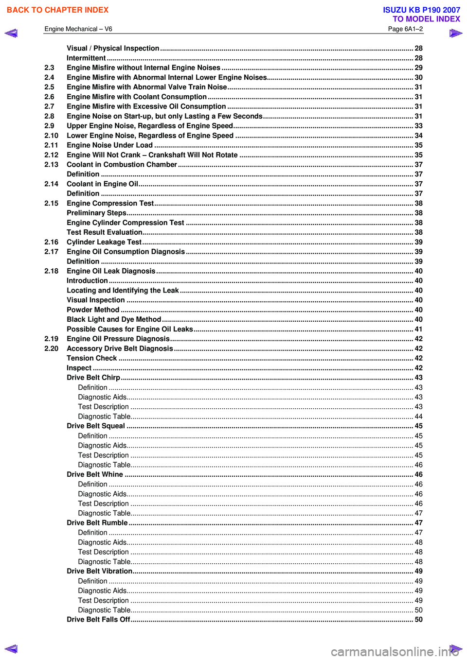
Visual / Physical Inspection ................................................................................................................................ 28
Intermittent ........................................................................................................................................................... 28
2.3 Engine Misfire without Internal Engine Noises .................................................................................. ............... 29
2.4 Engine Misfire with Abnormal Internal Lower Engine Noises...................................................................... .... 30
2.5 Engine Misfire with Abnormal Valve Train Noise .............................................................................................. 31
2.6 Engine Misfire with Coolant Consumption ........................................................................................................ 31
2.7 Engine Misfire with Excessive Oil Consumption .................................................................................. ............ 31
2.8 Engine Noise on Start-up, but only Lasting a Few Seconds ....................................................................... ..... 31
2.9 Upper Engine Noise, Regardless of Engine Speed........................................................................................... 33
2.10 Lower Engine Noise, Regardless of Engine Speed ................................................................................. ......... 34
2.11 Engine Noise Under Load ................................................................................................................................... 35
2.12 Engine Will Not Crank – Crankshaft Will Not Rotate ............................................................................. ........... 35
2.13 Coolant in Combustion Chamber ....................................................................................................................... 37
Definition .............................................................................................................................................................. 37
2.14 Coolant in Engine Oil.......................................................................................................... ................................. 37
Definition .............................................................................................................................................................. 37
2.15 Engine Compression Test ........................................................................................................ ........................... 38
Preliminary Steps................................................................................................................................................. 38
Engine Cylinder Compression Test ............................................................................................... .................... 38
Test Result Evaluation......................................................................................................................................... 38
2.16 Cylinder Leakage Test .......................................................................................................... ............................... 39
2.17 Engine Oil Consumption Diagnosis ............................................................................................... .................... 39
Definition .............................................................................................................................................................. 39
2.18 Engine Oil Leak Diagnosis ...................................................................................................... ............................ 40
Introduction .......................................................................................................................................................... 40
Locating and Identifying the Leak .............................................................................................. ........................ 40
Visual Inspection ................................................................................................................................................. 40
Powder Method .................................................................................................................. .................................. 40
Black Light and Dye Method ..................................................................................................... .......................... 40
Possible Causes for Engine Oil Leaks ........................................................................................... .................... 41
2.19 Engine Oil Pressure Diagnosis ........................................................................................................................... 42
2.20 Accessory Drive Belt Diagnosis ................................................................................................. ........................ 42
Tension Check ..................................................................................................................................................... 42
Inspect .................................................................................................................................................................. 42
Drive Belt Chirp .................................................................................................................................................... 43
Definition .......................................................................................................................................................... 43
Diagnostic Aids................................................................................................................................................. 43
Test Description ............................................................................................................... ................................ 43
Diagnostic Table............................................................................................................................................... 44
Drive Belt Squeal .............................................................................................................. ................................... 45
Definition .......................................................................................................................................................... 45
Diagnostic Aids................................................................................................................................................. 45
Test Description ............................................................................................................... ................................ 45
Diagnostic Table............................................................................................................................................... 46
Drive Belt Whine ............................................................................................................... ................................... 46
Definition .......................................................................................................................................................... 46
Diagnostic Aids................................................................................................................................................. 46
Test Description ............................................................................................................... ................................ 46
Diagnostic Table............................................................................................................................................... 47
Drive Belt Rumble .............................................................................................................. .................................. 47
Definition .......................................................................................................................................................... 47
Diagnostic Aids................................................................................................................................................. 48
Test Description ............................................................................................................... ................................ 48
Diagnostic Table............................................................................................................................................... 48
Drive Belt Vibration........................................................................................................... ................................... 49
Definition .......................................................................................................................................................... 49
Diagnostic Aids................................................................................................................................................. 49
Test Description ............................................................................................................... ................................ 49
Diagnostic Table............................................................................................................................................... 50
Drive Belt Falls Off ........................................................................................................... .................................... 50
BACK TO CHAPTER INDEX
TO MODEL INDEX
ISUZU KB P190 2007
Page 2488 of 6020

Engine Mechanical – V6 Page 6A1–9
• Faulty operation or performance of any systems or components which depend on the proper operation or
performance of the system or component under repair,
• Damage to fasteners, basic tools or special tools and / or
• Leakage of coolant, lubricant or other vital fluids.
NOTE defined
A NOTE statement immediately precedes or follows an operating procedure, maintenance practice or condition that
requires highlighting. A NOTE statement also emphasises necessary characteristics of a diagnostic or repair procedure.
A NOTE statement is designed to:
• Clarify a procedure,
• Present additional information for accomplishing a procedure,
• Give insight into the reasons for performing a procedure in the recommended manner, and / or
Present information that gives the technician the benefit of past experience in accomplishing a procedure with greater
ease.
1.2 Engine Components
Major Component Assemblies
BACK TO CHAPTER INDEX
TO MODEL INDEX
ISUZU KB P190 2007
Page 2491 of 6020

Engine Mechanical – V6 Page 6A1–12
Engine Front Cover
Figure 6A1 – 4
Legend
1 Engine Front Cover Locating Pin
2 Engine Front Cover Bolt, M10
3 Engine Front Cover
4 Engine Front Cover Gasket
5 Engine Front Cover Bolt, M8
6 Engine Front Cover Seal
7 Coolant Pump Assembly
8 Coolant Pump Bolt
9 Coolant Pump Gasket 10 Coolant Pump Pulley
11 Coolant Pump Pulley Bolt
12 Crankshaft Balancer
13 Crankshaft Balancer Bolt
14 Camshaft Position Sensor
15 Camshaft Position Sensor O-ring
16 Camshaft Position Sensor Bolt
17 Camshaft Position Actuator Solenoid Valve Seal
BACK TO CHAPTER INDEX
TO MODEL INDEX
ISUZU KB P190 2007
Page 2494 of 6020

Engine Mechanical – V6 Page 6A1–15
Cylinder Head Assembly
Figure 6A1 – 7
Legend
1 Cylinder Head, Left-hand
2 Cylinder Head, Right-hand
3 Cylinder Head Gasket, Left-hand
4 Cylinder Head Gasket, Right-hand
5 Cylinder Head Bolt
6 Cylinder Head Front Bolt
7 Cylinder Head Coolant Hole Threaded Plug
8 Spark Plug Sleeve
9 Cylinder Head Oil Gallery Expansion Plug
10 Exhaust Valve
11 Intake Valve
12 Valve Rocker Arm Assembly
13 Hydraulic Valve Lash Adjuster Assembly
14 Valve Stem Oil Seal 15 Valve Spring
16 Valve Spring Cap
17 Valve Stem Key
18 Cylinder Head Camshaft Front Thrust Bearing Cap
19 Camshaft Oil Seal Ring
20 Exhaust Camshaft
21 Intake Camshaft, Left-hand (bank 2)
22 Intake Camshaft, Right-hand (bank 1)
23 Exhaust Camshaft, Right-hand (bank 1)
24 Cylinder Head Camshaft Cap – Intermediate
25 Cylinder Head Camshaft Cap Bolt
26 Cylinder Head Oil Galley Check Valve
27 Engine Coolant Temperature Sensor
BACK TO CHAPTER INDEX
TO MODEL INDEX
ISUZU KB P190 2007
Page 2496 of 6020

Engine Mechanical – V6 Page 6A1–17
Engine Block Assembly
Figure 6A1 – 9
Legend
1 Piston and Connecting Rod Assembly
2 Crankshaft Bearing Cap
3 Crankshaft Bearing Thrust Cap
4 Crankshaft Bearing Cap Inboard Bolt
5 Crankshaft Bearing Cap Outboard Bolt
6 Crankshaft Bearing Cap Side Bolt, Short
7 Crankshaft Bearing Cap Side Bolt, Long
8 Engine Block Oil Gallery Expansion Plug, 10 mm
9 Crankshaft
10 Crankshaft Sprocket Locating Pin
11 Crankshaft Upper Bearing
12 Crankshaft Lower Bearing
13 Crankshaft Upper Thrust Bearing #3 14 Engine Block Oil Gallery Expansion Plug, 14 mm
15 Engine Block Oil Gallery Threaded Plug, 14 mm
16 Engine Block Coolant Drain Threaded Plug, 14 mm
17 Engine Block Oil Gallery Threaded Plug, 20 mm
18 Engine Block Core Coolant Expansion Plug, 34.3 mm
19 Transaxle Locating Pin
20 Crankshaft Rear Oil Seal Housing Assembly
21 Crankshaft Rear Oil Seal Housing Assembly Bolt
22 Oil Pan Locating Pin
23 Cylinder Head Locating Pin
24 Piston Oil Nozzle
25 Piston Oil Nozzle Bolt
BACK TO CHAPTER INDEX
TO MODEL INDEX
ISUZU KB P190 2007
Page 2509 of 6020

Engine Mechanical – V6 Page 6A1–30
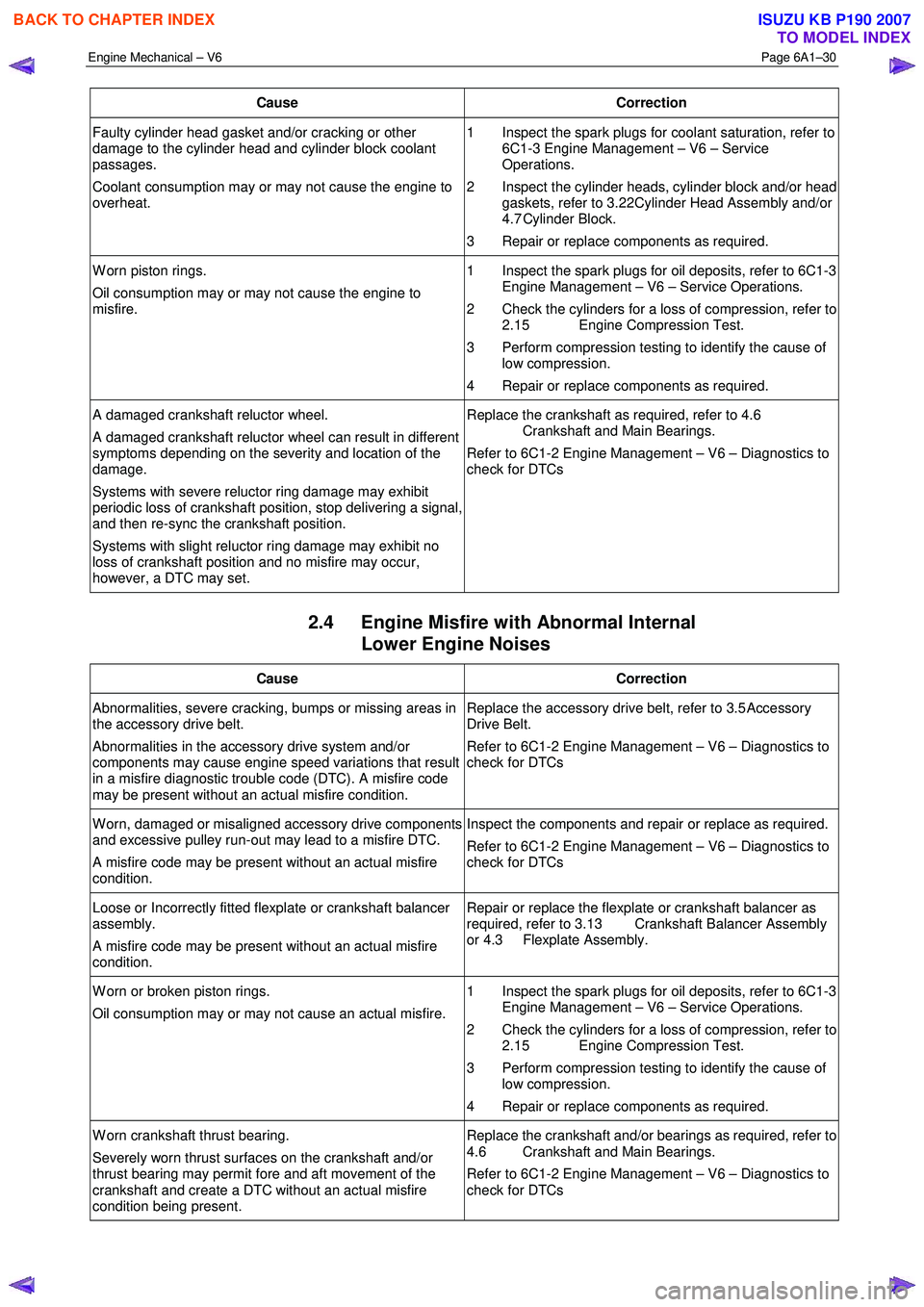
Cause Correction
Faulty cylinder head gasket and/or cracking or other
damage to the cylinder head and cylinder block coolant
passages.
Coolant consumption may or may not cause the engine to
overheat. 1 Inspect the spark plugs for coolant saturation, refer to
6C1-3 Engine Management – V6 – Service
Operations.
2 Inspect the cylinder heads, cylinder block and/or head gaskets, refer to 3.22 Cylinder Head Assembly and/or
4.7 Cylinder Block.
3 Repair or replace components as required.
W orn piston rings.
Oil consumption may or may not cause the engine to
misfire. 1 Inspect the spark plugs for oil deposits, refer to 6C1-3
Engine Management – V6 – Service Operations.
2 Check the cylinders for a loss of compression, refer to 2.15 Engine Compression Test.
3 Perform compression testing to identify the cause of low compression.
4 Repair or replace components as required.
A damaged crankshaft reluctor wheel.
A damaged crankshaft reluctor wheel can result in different
symptoms depending on the severity and location of the
damage.
Systems with severe reluctor ring damage may exhibit
periodic loss of crankshaft position, stop delivering a signal,
and then re-sync the crankshaft position.
Systems with slight reluctor ring damage may exhibit no
loss of crankshaft position and no misfire may occur,
however, a DTC may set. Replace the crankshaft as required, refer to 4.6
Crankshaft and Main Bearings.
Refer to 6C1-2 Engine Management – V6 – Diagnostics to
check for DTCs
2.4 Engine Misfire with Abnormal Internal Lower Engine Noises
Cause Correction
Abnormalities, severe cracking, bumps or missing areas in
the accessory drive belt.
Abnormalities in the accessory drive system and/or
components may cause engine speed variations that result
in a misfire diagnostic trouble code (DTC). A misfire code
may be present without an actual misfire condition. Replace the accessory drive belt, refer to 3.5
Accessory
Drive Belt.
Refer to 6C1-2 Engine Management – V6 – Diagnostics to
check for DTCs
W orn, damaged or misaligned accessory drive components
and excessive pulley run-out may lead to a misfire DTC.
A misfire code may be present without an actual misfire
condition. Inspect the components and repair or replace as required.
Refer to 6C1-2 Engine Management – V6 – Diagnostics to
check for DTCs
Loose or Incorrectly fitted flexplate or crankshaft balancer
assembly.
A misfire code may be present without an actual misfire
condition. Repair or replace the flexplate or crankshaft balancer as
required, refer to 3.13 Crankshaft Balancer Assembly
or 4.3 Flexplate Assembly.
W orn or broken piston rings.
Oil consumption may or may not cause an actual misfire. 1 Inspect the spark plugs for oil deposits, refer to 6C1-3
Engine Management – V6 – Service Operations.
2 Check the cylinders for a loss of compression, refer to 2.15 Engine Compression Test.
3 Perform compression testing to identify the cause of low compression.
4 Repair or replace components as required.
W orn crankshaft thrust bearing.
Severely worn thrust surfaces on the crankshaft and/or
thrust bearing may permit fore and aft movement of the
crankshaft and create a DTC without an actual misfire
condition being present. Replace the crankshaft and/or bearings as required, refer to
4.6 Crankshaft and Main Bearings.
Refer to 6C1-2 Engine Management – V6 – Diagnostics to
check for DTCs
BACK TO CHAPTER INDEX
TO MODEL INDEX
ISUZU KB P190 2007