engine mount ISUZU KB P190 2007 Workshop Repair Manual
[x] Cancel search | Manufacturer: ISUZU, Model Year: 2007, Model line: KB P190, Model: ISUZU KB P190 2007Pages: 6020, PDF Size: 70.23 MB
Page 3068 of 6020

Engine Mechanical – V6 Page 6A1–291
Page 6A1–291
Crankshaft Final Installation Procedure
1 If removed, install the crankshaft sprocket drive
pin (1). Lightly tap the pin in place with a small soft
face, bronze/plastic, hammer until it bottoms in the
hole.
Figure 6A1 – 522
CAUTION
Ensure the crankshaft position sensor has
been removed from the cylinder block prior
to loading the crankshaft, as damage to the
sensor may occur.
2 Apply a liberal amount of clean engine oil to the upper and lower bearing surfaces.
3 Gently lower the crankshaft (1) into position in the cylinder block (2).
Figure 6A1 – 523
4 Install the crankshaft main bearing caps.
5 Loosely install the original inner main cap bolts (1).
CAUTION
The outer crankshaft bearing cap bolts (2)
are yield tightened during assembly and
must be replaced prior to reassembly. Outer
crankshaft bearing cap bolts that are not
replaced will not torque to the correct clamp
load and can lead to serious engine damage.
6 Loosely install the new outer main bearing cap bolts (2).
7 Gently tap the crankshaft main bearing caps with a soft-faced hammer to help seat the caps.
Figure 6A1 – 524
BACK TO CHAPTER INDEX
TO MODEL INDEX
ISUZU KB P190 2007
Page 3074 of 6020

Engine Mechanical – V6 Page 6A1–297
Page 6A1–297
Clean
1 Remove all thread sealant, gasket material or sealant using a commercially available plastic or wood scraper.
2 Clean all the following areas with a suitable solvent:
• sealing surfaces,
• cooling passages,
• oil passages, and
• bearing journals.
3 Clean all threaded and through holes with a suitable solvent.
Safety glasses must be worn when using
compressed air.
4 Dry the engine block with compressed air.
Inspect
Visual Inspection
NOTE
The following procedure assumes the engine has
been disassembled and cleaned, as described
above.
1 Inspect the crankshaft bearing journals for damage or spun bearings. The crankshaft bearing journals are not
repairable and if damage is f ound, the cylinder block assembly must be replaced.
2 Inspect the primary camshaft chain t ensioner mounting surface on the engine block for burrs or any defects that
would affect the sealing of the new primary camshaft chain tensioner gasket.
3 Inspect all sealing and mating surfaces for damage, repair or replace the cylinder block assembly if required.
4 Inspect all threaded and through holes for damage or excessive debris.
5 Inspect all bolts for damage, if damaged replace with new bolts only.
6 Inspect the cylinder walls for cracks or damage. The cyli nder sleeves are not serviced separately, if the cylinders
are damaged the cylinder block assembly must be replaced.
7 Inspect the engine block for cracks. Do not repair any cra cks. If cracks are found, the cylinder block assembly must
be replaced. Repair any damaged threaded holes, refer to 4.9 Thread Repair Specifications.
Measuring Cylinder Bore Diameter
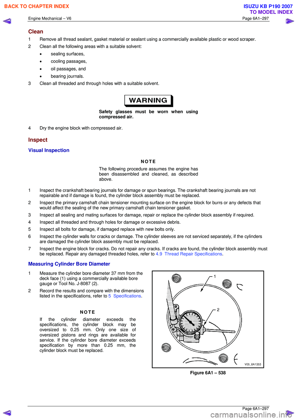
1 Measure the cylinder bore diameter 37 mm from the
deck face (1) using a commercially available bore
gauge or Tool No. J-8087 (2).
2 Record the results and compare with the dimensions listed in the specifications, refer to 5 Specifications.
NOTE
If the cylinder diameter exceeds the
specifications, the cylinder block may be
oversized to 0.25 mm. Only one size of
oversized pistons and rings are available for
service. If the cylinder bore diameter exceeds
specification by mo re than 0.25 mm, the
cylinder block must be replaced.
Figure 6A1 – 538
BACK TO CHAPTER INDEX
TO MODEL INDEX
ISUZU KB P190 2007
Page 3075 of 6020

Engine Mechanical – V6 Page 6A1–298
Page 6A1–298
Measuring Cylinder Bore Taper
1 Measure the cylinder bore along the thrust surfaces, perpendicular to the crankshaft centreline, at 10 mm below the
deck surface and record the measurement.
2 Measure the cylinder bore along the th rust surfaces, perpendicular to the crankshaft centreline, at 100 mm below
the deck surface and record the measurement.
3 Calculate the difference betw een the two measurements. The re sult will be the cylinder taper.
4 Compare the results with the dimensions listed in the specifications, refer to 5 Specifications.
NOTE
If the cylinder diameter exceeds the
specifications, the cylinder block may be
oversized to 0.25 mm. Only one size of oversized
pistons and rings are available for service. If the
cylinder bore diameter ex ceeds specification by
more than 0.25 mm, the cylinder block must be
replaced.
Measuring Cylinder Bore Out-of-Round
1 Measure both the thrust and non-thrust cylinder diameter at 10 mm below the deck. Record your measurements.
2 Calculate the difference bet ween the two measurements. The result will indicate out-of-r ound at the upper end of
the cylinder.
3 Measure both the thrust and non-thru st cylinder diameter at 100 mm below the deck surface. Record your
measurements.
4 Calculate the difference between the tw o measurements. The result will indicate out-of-round at the lower end of
the cylinder.
5 Compare your results with the dimensions listed in the specifications, refer to 5 Specifications.
NOTE
If the cylinder diameter exceeds the
specifications, the cylinder block may be
oversized to 0.25 mm. Only one size of oversized
pistons and rings are available for service. If the
cylinder bore diameter ex ceeds specification by
more than 0.25 mm, the cylinder block must be
replaced.
Deck Flatness Inspection
1 Ensure the engine block decks are clean and free of gasket material.
2 Inspect the surface for any imperfections or scratches
that could inhibit correct cylinder head gasket sealing.
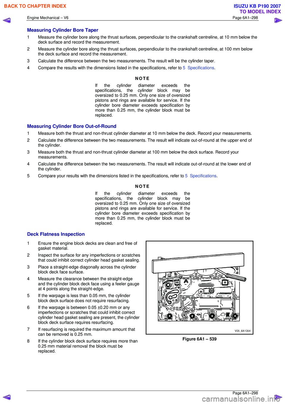
3 Place a straight-edge diagonally across the cylinder block deck face surface.
4 Measure the clearance between the straight-edge
and the cylinder block deck face using a feeler gauge
at 4 points along the straight-edge.
5 If the warpage is less t han 0.05 mm, the cylinder
block deck surface does not require resurfacing.
6 If the warpage is between 0.05 ±0.20 mm or any imperfections or scratches that could inhibit correct
cylinder head gasket sealing are present, the cylinder
block deck surface requires resurfacing.
7 If resurfacing is requir ed the maximum amount that
can be removed is 0.25 mm.
8 If the cylinder block deck surface requires more than 0.25 mm material removal the block must be
replaced.
Figure 6A1 – 539
BACK TO CHAPTER INDEX
TO MODEL INDEX
ISUZU KB P190 2007
Page 3128 of 6020

Engine Mechanical – V6 Page 6A1–351
Page 6A1–351
6 Torque Wrench Specifications
ATTENTION
�„ Fasteners must be replaced after loosening.
Fasteners either have micro encapsulated sealant a pplied or incorporate a mechanical thread lock and
should only be re-used once. If in doubt, replacement is recommended.
Oil Pan Drain Plug ................................................................................ 25.0 Nm
Oil Filter Adaptor Attach ing Bolt................................................ 20.0 – 26.0 Nm
Oil Level Indicator Tube Atta ching Bolt........................................ 8.0 – 12.0 Nm
Accessory Drive Belt Idler Pu lley Attaching Bolt................................... 50.0 Nm
Accessory Drive Belt Tensio ner Attaching Bolt .................................... 50.0 Nm
Power Steering Reserv oir Bracket Attaching Screw.............................. 9.0 Nm
Power Steering Pump Bracket A ttaching Bolt ........................... 49. 0 – 67.0 Nm
Upper Intake Manifold to Lower Intake Manifold Attaching Bolt ........... 23.0 Nm
Upper Intake Manifold to Cylinder Head Attaching Bolt........................ 23.0 Nm
Lower Intake Manifold to Cylind er Head Attaching Bolt........................ 23.0 Nm
Fuel Injector Wiring Harness Br acket Attaching bolt .............................. 9. 0 Nm
Exhaust Manifold to Cylinder He ad Attaching Bolt..................... 17.0 - 23.0 Nm
Exhaust Manifold Heat Shield Attaching Bolt ............................... 8.0 - 12.0 Nm
Battery Harness Ground Terminal Attaching Nut ................................. 13. 0 Nm
Camshaft Cover Attachi ng Bolt................................................... 8.0 – 12.0 Nm
Engine Ground Connec tor Bolt............................................................. 10.0 Nm
Engine Wiring Harness Former A ttaching Bolt .......................... 12.0 – 16.0 Nm
�„ Crankshaft Balancer A ssembly Attaching Bolt:
Stage 1 ..................................................................................... 90.0 –110.0 Nm
Stage 2 ....................................................................................................... 150 °
Engine Front Cover Assembly A ttaching Bolt ............................ 20. 0 – 26.0 Nm
Camshaft Intermediate Sprocket Attaching Bolt ........................ 58. 0 – 72.0 Nm
Secondary Timing Chai n Guide Attaching Bolt.......................... 20.0 – 26.0 Nm
Secondary Timing Chai n Shoe Attaching Bolt ........................... 20.0 – 26.0 Nm
Secondary Timing Chain Tensioner Attachi ng Bolt ................... 20.0 – 26.0 Nm
Primary Timing Chain Upper Gui de Attaching Bolt.................... 20.0 – 26.0 Nm
Primary Timing Chain Tensioner Attaching Bolt........................ 20. 0 – 26.0 Nm
Oil Pump Assembly Attach ing Bolt............................................ 20.0 – 26.0 Nm
Camshaft Sprocket Attachi ng Bolt............................................. 49.0 – 67.0 Nm
Exhaust Camshaft Sprocket Atta ching Bolt............................... 49.0 – 67.0 Nm
Camshaft Bearing Cap Attach ing Bolt......................................... 8.0 – 12.0 Nm
Cylinder Head Thr eaded Plug.............................................................. 31.0 Nm
�„ Cylinder Head M11 Attaching Bolt:
Stage 1 ...................................................................................... 40.0 – 50.0 Nm
Stage 2 ....................................................................................................... 120 °
�„ Cylinder Head M8 Attaching Bolt:
Stage 1 ...................................................................................... 12.0 – 18.0 Nm
Stage 2 ......................................................................................................... 60 °
Engine Mount Bracket to Cylinder Bl ock Attaching Bolt............ 43.0 – 57.0 Nm
Engine Mount to Bracket Atta ching Nut..................................... 70.0 – 90.0 Nm
Engine Mount to Frame Atta ching Nut...................................... 44.0 – 60.0 Nm
Engine Lift Bracket Attachi ng Bolt.......................................... 58.0 – 72.0.0 Nm
Knock Sensor Attach ing Nut................................................................. 23.0 Nm
BACK TO CHAPTER INDEX
TO MODEL INDEX
ISUZU KB P190 2007
Page 3129 of 6020

Engine Mechanical – V6 Page 6A1–352
Page 6A1–352
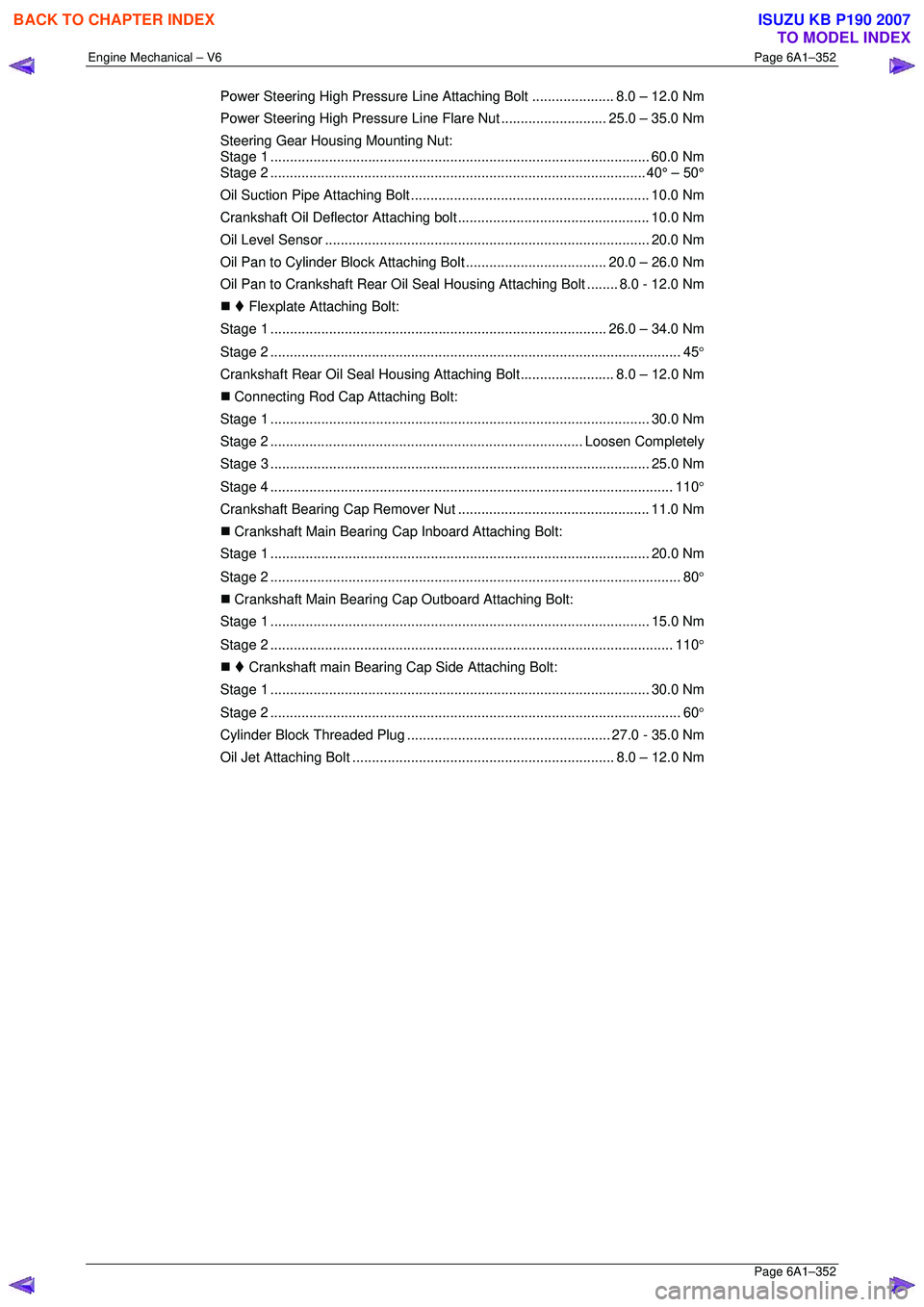
Power Steering High Pressure Line Attaching Bolt..................... 8.0 – 12.0 Nm
Power Steering High Pressure Li ne Flare Nut ...........................25.0 – 35.0 Nm
Steering Gear Housing Mounting Nut:
Stage 1 ................................................................................................. 60.0 Nm
Stage 2 ................................................................................................ 40° – 50°
Oil Suction Pipe Attaching Bolt ............................................................. 10.0 Nm
Crankshaft Oil Deflector Attaching bolt ................................................. 10. 0 Nm
Oil Level Sens or ................................................................................... 20.0 Nm
Oil Pan to Cylinder Block A ttaching Bolt .................................... 20.0 – 26.0 Nm
Oil Pan to Crankshaft Rear Oil Seal Housing Attaching Bolt ........ 8.0 - 12.0 Nm
�„ Flexplate Attaching Bolt:
Stage 1 ...................................................................................... 26.0 – 34.0 Nm
Stage 2 ......................................................................................................... 45 °
Crankshaft Rear Oil Seal Housi ng Attaching Bolt........................ 8.0 – 12.0 Nm
�„ Connecting Rod Cap Attaching Bolt:
Stage 1 ................................................................................................. 30.0 Nm
Stage 2 ................................................................................ Loos en Completely
Stage 3 ................................................................................................. 25.0 Nm
Stage 4 ....................................................................................................... 110 °
Crankshaft Bearing Cap Remover Nut................................................. 11.0 Nm
�„ Crankshaft Main Bearing Cap Inboard Attaching Bolt:
Stage 1 ................................................................................................. 20.0 Nm
Stage 2 ......................................................................................................... 80 °
�„ Crankshaft Main Bearing Cap Outboard Attaching Bolt:
Stage 1 ................................................................................................. 15.0 Nm
Stage 2 ....................................................................................................... 110 °
�„ Crankshaft main Bearing Cap Side Attaching Bolt:
Stage 1 ................................................................................................. 30.0 Nm
Stage 2 ......................................................................................................... 60 °
Cylinder Block Threaded Plug .................................................... 27.0 - 35.0 Nm
Oil Jet Attaching Bo lt ................................................................... 8.0 – 12.0 Nm
BACK TO CHAPTER INDEX
TO MODEL INDEX
ISUZU KB P190 2007
Page 3138 of 6020

Engine Cooling – V6 Engine Page 6B1–3
1 General Information
The cooling system for the HFV6 engine has been re-designed to accommodate this engine’s unique configuration and
engine cooling performance requirements. The following list is a summary of new and modified components:
• Revised radiator assembly.
• New plumbing including radiator hoses, inlet pipe, heater pipes, heater hoses and heater water valve.
• New rear mount thermostat assembly and thermostat housing.
• New coolant outlet with pressure cap.
• New coolant specification.
• New side chutes and radiator shroud.
• Modified cooling fan operating strategy.
• A four stage cooling fan operating system is used.
The cooling fan motor is controlled by duty signal from the ECM which results in the fan operating from low speed Stage
1), up to high speed (Stage 4).
Operation of the cooling fan is dependant on the engine temperature, vehicle speed, A/C request (where fitted) and A/C
system pressure. Refer to 6C1 – 1 Engine management general information.
BACK TO CHAPTER INDEX
TO MODEL INDEX
ISUZU KB P190 2007
Page 3140 of 6020

Engine Cooling – V6 Engine Page 6B1–5
2 General Description
2.1 Radiator Assembly
The radiator has an aluminium core and is of the cross-flow design. Plastic side tanks are attached to the core by clinch
tabs. The clinch tabs are formed as part of the core assembly.
The lower frame of the radiator assembly is attached to the vehicle frame by two bolts supported in rubber mounts, pegs
are attached to the upper area of each side tank. These pegs are used to support the radiator with two rubber insert
mounting brackets.
A high temperature rubber seal is used to seal the mating surface between the core and each side tank. The seal(s)
must be replaced any time the side tank is removed from the core.
NOTE
The radiator core side tanks or transmission oil
cooler cannot be replaced separately. If there is a
fault with any of these components, the radiator
assembly must be replaced. Small core repairs
may be made using an aluminised silicon based
liquid repair agent. Refer to 3.15 Radiator in
this Section.
For vehicles with automatic transmission, a transmission oil cooler is located in the right-hand side radiator tank. The
cooler pipes from and to the transmission are connected to the oil cooler flexible hoses by means of quick connect
fittings.
The cooling fan motor is attached by three screws to the one-piece plastic fan shroud. In turn, the fan shroud is mounted
to the rear of the radiator and is located and supported by two bolts and two locating tabs. The upper clips lock the fan
shroud in place and can be released by hand to facilitate fan shroud removal. The shroud must be removed to allow fan
motor and blade assembly removal.
One harness connector is mounted to the upper section of the fan shroud allowing the fan motor and blade assemblies
to be removed individually from the shroud. The fan motor and blade is balanced as an assembly. These two
components are serviced only as a unit and are not to be separated.
The shroud, fan assembly and transmission cooler hoses can be removed and installed individually from the vehicle. For
removal and installation procedures, refer to 3.13Cooling Fan and Shroud Assembly, 3.14 Flexible Transmission
Cooler Hose and 3.15 Radiator in this Section.
BACK TO CHAPTER INDEX
TO MODEL INDEX
ISUZU KB P190 2007
Page 3145 of 6020

Engine Cooling – V6 Engine Page 6B1–10
Fan Assembly connector
Figure 6B1 – 5
2.3 Coolant Pump
The coolant pump is a centrifugal vane impeller type pump. The pump consists of a housing and an impeller. The
impeller is a flat plate mounted on the pump shaft with a series of flat or curved blades (vanes). W hen the impeller
rotates, the coolant between the vanes is thrown outward by centrifugal force. The impeller shaft is supported by sealed
bearings. The sealed bearings do not need to be lubricated. Grease cannot leak out, dirt and water cannot get in as long
as the seal is not damaged or worn.
The coolant pump (1) is mounted to the engine front cover
and is driven by the crankshaft pulley (2) via a multi-ribbed
drive belt (3), turning the pump pulley (4), bolted to the
coolant pump flange (5). Coolant enters the engine
through the coolant inlet pipe and thermostat at the rear of
engine and passes through the engine to the coolant
pump on the front engine cover and exits via the coolant
outlet housing (6) located at the front of the intake
manifold.
Figure 6B1 – 6
BACK TO CHAPTER INDEX
TO MODEL INDEX
ISUZU KB P190 2007
Page 3150 of 6020

Engine Cooling – V6 Engine Page 6B1–15
2.8 Engine Coolant Temperature Sensor
An Engine Coolant Temperature (ECT) sensor (2) is
mounted in the left-hand side cylinder head, just above
the exhaust manifold. The ECT sensor is used in
conjunction with the instrument panel temperature gauge.
The ECT sensor generates a signal, which is used by the
engine management system for calculation of the various
engine management functions.
Figure 6B1 – 13 shows the wiring harness connector (1)
and the ECT sensor (2).
Refer to 6C1-1 Engine Management General Information
for further information on the ECT sensor.
Figure 6B1 – 13
BACK TO CHAPTER INDEX
TO MODEL INDEX
ISUZU KB P190 2007
Page 3155 of 6020

Engine Cooling – V6 Engine Page 6B1–20
COOLANT CONCENTRATION
Litres Of Coolant To Be Added
Concentration Reading % Automatic Transmission Manual Transmission
0 4.95 5.15
5 4.46 4.62
10 3.96 4.12
15 3.47 3.61
20 2.97 3.08
25 2.48 2.57
30 1.98 2.01
35 1.48 1.54
40 0.99 1.05
45 0.50 0.52
50 0 0
NOTE
If the reading is not clear, then properly clean
and dry the measuring surface, then conduct
another test. Also ensure that there is
sufficient fluid on the measuring prism.
9 If the reading shows that the concentration level of the coolant is inadequate, refer to the Coolant
Concentration table to determine the amount of
coolant that needs to be added to the coolant
recovery reservoir.
10 Start and run the engine until normal operating temperature is reached, to allow the added coolant
to be distributed throughout the engine cooling
system.
Figure 6B1 – 17
BACK TO CHAPTER INDEX
TO MODEL INDEX
ISUZU KB P190 2007