engine mount ISUZU KB P190 2007 Workshop Repair Manual
[x] Cancel search | Manufacturer: ISUZU, Model Year: 2007, Model line: KB P190, Model: ISUZU KB P190 2007Pages: 6020, PDF Size: 70.23 MB
Page 2986 of 6020
Engine Mechanical – V6 Page 6A1–209
Page 6A1–209
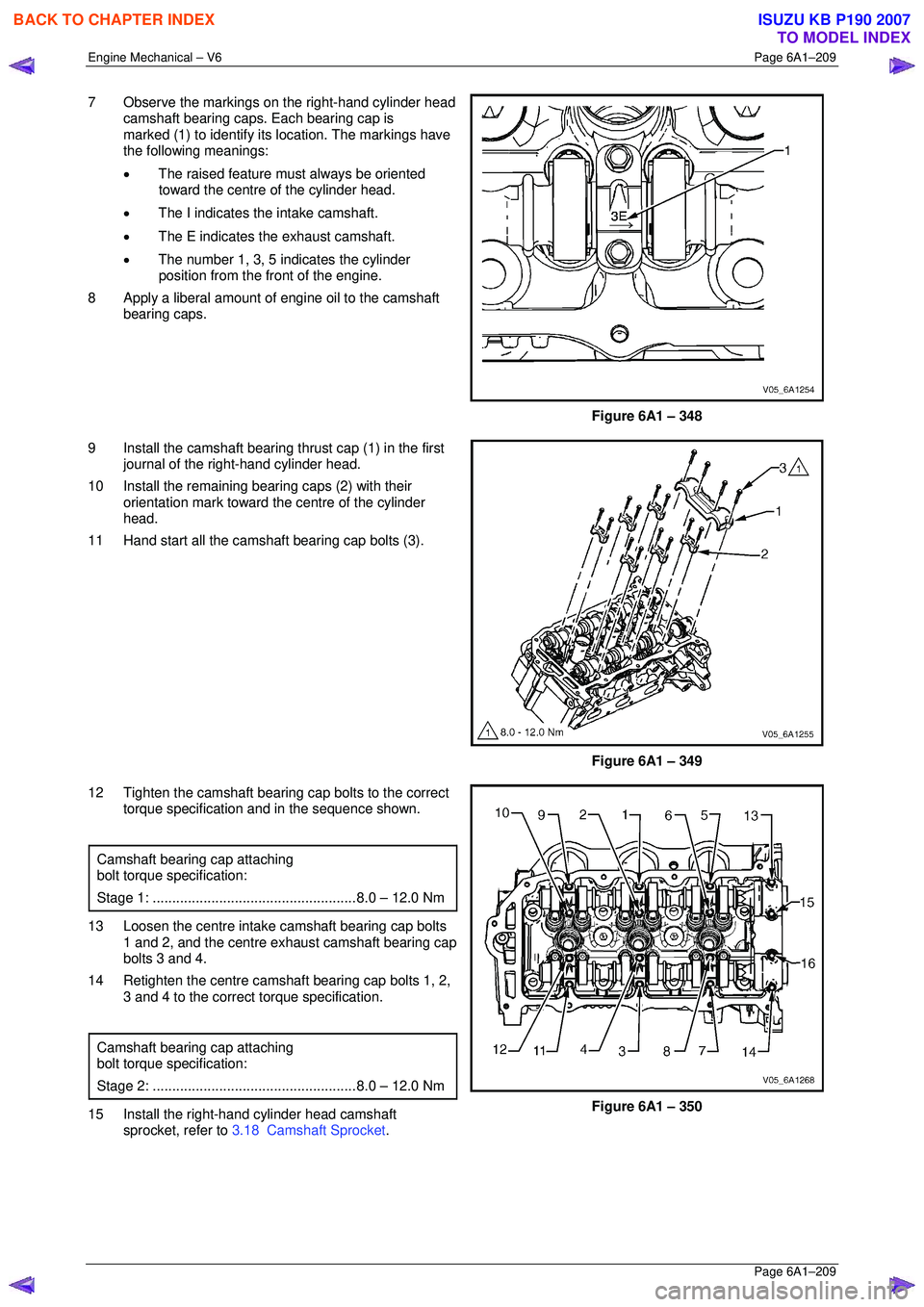
7 Observe the markings on the right-hand cylinder head
camshaft bearing caps. Each bearing cap is
marked (1) to identify its location. The markings have
the following meanings:
• The raised feature must always be oriented
toward the centre of the cylinder head.
• The I indicates the intake camshaft.
• The E indicates the exhaust camshaft.
• The number 1, 3, 5 indicates the cylinder
position from the fr ont of the engine.
8 Apply a liberal amount of engine oil to the camshaft bearing caps.
Figure 6A1 – 348
9 Install the camshaft bearing thrust cap (1) in the first journal of the right-hand cylinder head.
10 Install the remaining bearing caps (2) with their orientation mark toward t he centre of the cylinder
head.
11 Hand start all the camshaft bearing cap bolts (3).
Figure 6A1 – 349
12 Tighten the camshaft bearing cap bolts to the correct torque specification and in the sequence shown.
Camshaft bearing cap attaching
bolt torque specification:
Stage 1: .................................................... 8.0 – 12.0 Nm
13 Loosen the centre intake camshaft bearing cap bolts
1 and 2, and the centre exhaust camshaft bearing cap
bolts 3 and 4.
14 Retighten the centre camsha ft bearing cap bolts 1, 2,
3 and 4 to the correct torque specification.
Camshaft bearing cap attaching
bolt torque specification:
Stage 2: .................................................... 8.0 – 12.0 Nm
15 Install the right-hand cylinder head camshaft
sprocket, refer to 3.18 Camshaft Sprocket .
Figure 6A1 – 350
BACK TO CHAPTER INDEX
TO MODEL INDEX
ISUZU KB P190 2007
Page 2987 of 6020
Engine Mechanical – V6 Page 6A1–210
Page 6A1–210
Left-hand Side
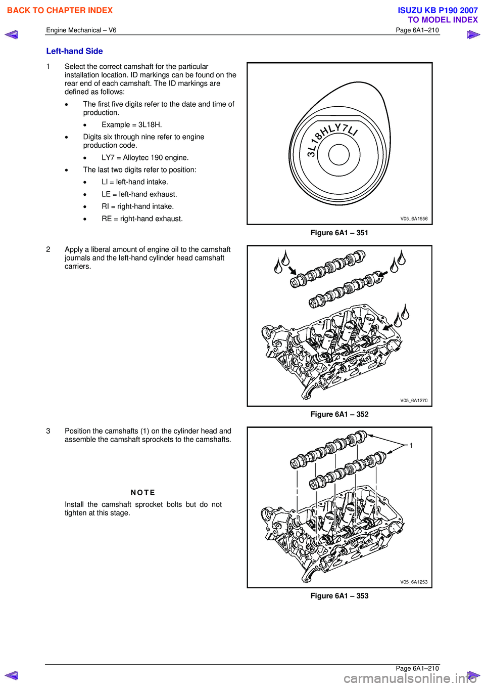
1 Select the correct camshaft for the particular
installation location. ID markings can be found on the
rear end of each camshaft. The ID markings are
defined as follows:
• The first five digits refer to the date and time of
production.
• Example = 3L18H.
• Digits six through nine refer to engine
production code.
• LY7 = Alloytec 190 engine.
• The last two digits refer to position:
• LI = left-hand intake.
• LE = left-hand exhaust.
• RI = right-hand intake.
• RE = right-hand exhaust.
Figure 6A1 – 351
2 Apply a liberal amount of engine oil to the camshaft journals and the left-hand cylinder head camshaft
carriers.
Figure 6A1 – 352
3 Position the camshafts (1) on the cylinder head and assemble the camshaft spro ckets to the camshafts.
NOTE
Install the camshaft sprocket bolts but do not
tighten at this stage.
Figure 6A1 – 353
BACK TO CHAPTER INDEX
TO MODEL INDEX
ISUZU KB P190 2007
Page 2988 of 6020
Engine Mechanical – V6 Page 6A1–211
Page 6A1–211
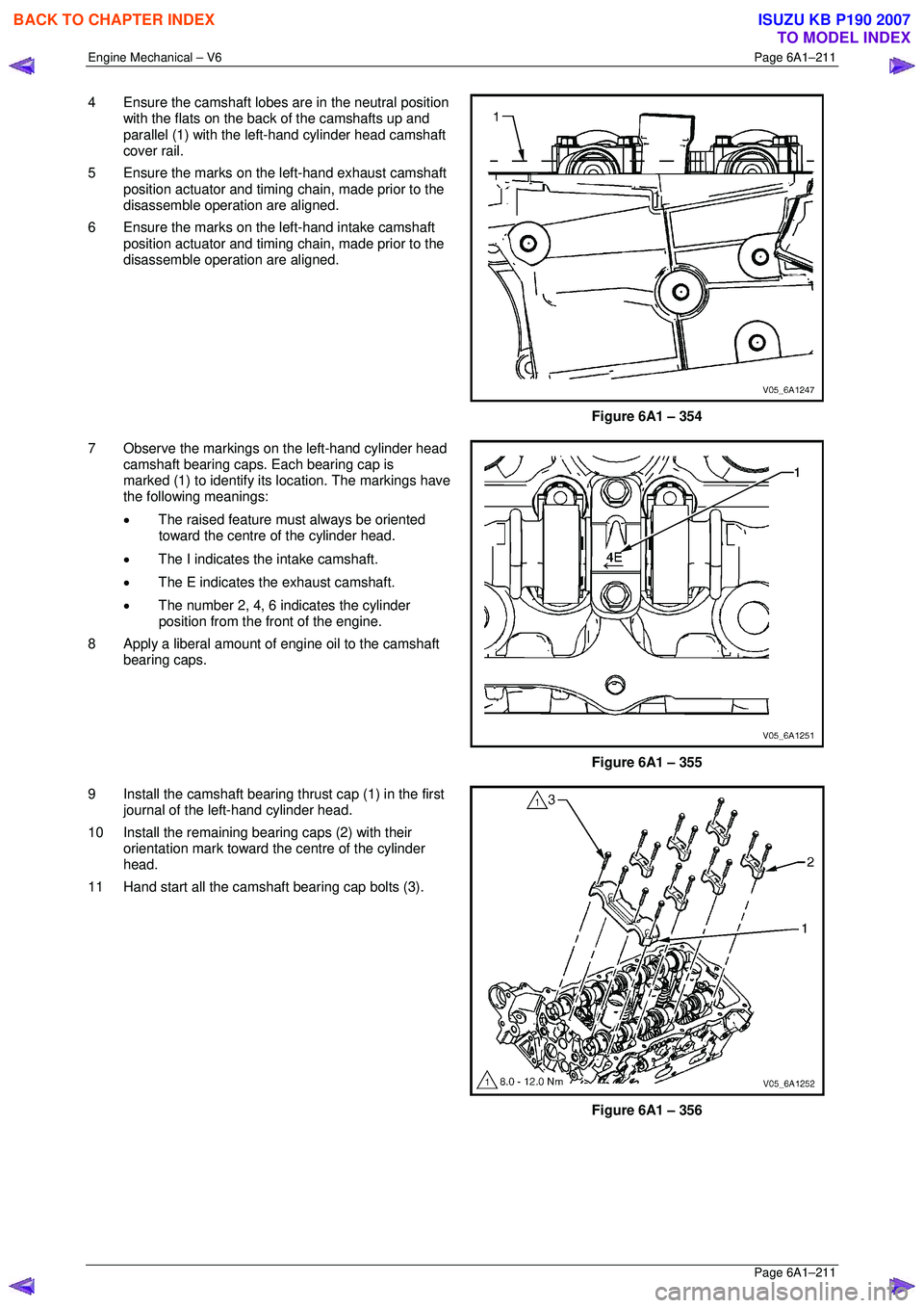
4 Ensure the camshaft lobes are in the neutral position
with the flats on the back of the camshafts up and
parallel (1) with the left-hand cylinder head camshaft
cover rail.
5 Ensure the marks on the left-hand exhaust camshaft position actuator and timing chain, made prior to the
disassemble operation are aligned.
6 Ensure the marks on the left-hand intake camshaft position actuator and timing chain, made prior to the
disassemble operation are aligned.
Figure 6A1 – 354
7 Observe the markings on the left-hand cylinder head camshaft bearing caps. Each bearing cap is
marked (1) to identify its location. The markings have
the following meanings:
• The raised feature must always be oriented
toward the centre of the cylinder head.
• The I indicates the intake camshaft.
• The E indicates the exhaust camshaft.
• The number 2, 4, 6 indicates the cylinder
position from the fr ont of the engine.
8 Apply a liberal amount of engine oil to the camshaft bearing caps.
Figure 6A1 – 355
9 Install the camshaft bearing thrust cap (1) in the first journal of the left-hand cylinder head.
10 Install the remaining bearing caps (2) with their orientation mark toward t he centre of the cylinder
head.
11 Hand start all the camshaft bearing cap bolts (3).
Figure 6A1 – 356
BACK TO CHAPTER INDEX
TO MODEL INDEX
ISUZU KB P190 2007
Page 2991 of 6020

Engine Mechanical – V6 Page 6A1–214
Page 6A1–214
Reinstall
1 Apply a liberal amount of commercially available
camshaft / lifter prelube or equivalent to the pivot
pocket (1), roller (2) and valve slot (3) areas of the
camshaft followers.
Figure 6A1 – 360
2 Place the rocker arm in position on the valve tip and stationary hydraulic lash adjuster (SHLA). The
rounded head end of the arm seats on the SHLA
while the flat end seats on the valve tip.
CAUTION
• The rocker arm (1) must be positioned
squarely on the valve tip so the full width
of the roller will completely contact the
camshaft lobe.
• If the rocker arms are being reused, they
must be reinstalled in their original
location.
3 Clean the camshaft journals and carriers with a clean, lint-free cloth.
4 Reinstall the camshafts, refer to 3.19 Camshaft.
Figure 6A1 – 361
BACK TO CHAPTER INDEX
TO MODEL INDEX
ISUZU KB P190 2007
Page 2993 of 6020

Engine Mechanical – V6 Page 6A1–216
Page 6A1–216
Reinstall
1 Fill the stationary hydraulic lash adjuster (SHLA) with
clean engine oil. Take precautions to prevent
scratching the pivot s phere area of the SHLA.
2 Lubricate the SHLA bores in the cylinder head with clean engine oil.
3 Install the SHLA in the cylinder head (2).
4 Apply a liberal amount of commercially available camshaft/lifter prelube to the SHLA pivot spheres.
5 Install the rocker arms, refer to 3.20 Rocker Arm.
CAUTION
Ensure each lash adjuster (1) is filled with
clean engine oil and the adjuster does not
tip over, plunger down, before the
installation. The loss of oil in the adjuster
lower pressure chamber, or the dry
stroking/cycling of the adjuster plunger, will
allow air to enter the high pressure chamber
of the valve lifter. Air in the high pressure
chamber of the adjuster may not be purged
causing cavitation and extensive engine
component damage.
Figure 6A1 – 364
BACK TO CHAPTER INDEX
TO MODEL INDEX
ISUZU KB P190 2007
Page 2995 of 6020

Engine Mechanical – V6 Page 6A1–218
Page 6A1–218
Left-hand Side (Bank 2) Cylinder Head
1 Remove the intake manifold assembly, refer to 3.10 Intake Manifold Assembly – Complete .
2 Remove the exhaust manifold, refer to 3.11 Exhaust Manifold Assembly.
3 Remove the power steering reservoi r and pump mounting brackets, refer to 3.8 Power Steering Pump Bracket.
NOTE
Do not disconnect the power steering pipes
and/or hoses.
4 Remove the oil filter adapter upper bolt. NOTE
Do not remove the oil filter adapter.
5 Remove the engine coolant temper ature (ECT) sensor, refer to Section 6C1-3 Engine Management – V6 – Service
Operations .
6 Remove engine harness ground terminal attach ing bolt from cylinder head, refer to Section 8A Electrical Body &
Chassis .
7 Remove the left-hand bank secondary timing chain, refer to 3.16 Timing Chains, Tensioners, Shoes and Guides.
8 Remove the camshaft position actuators, refer to 3.18 Camshaft Sprocket.
9 Remove the front M8 (1) cylinder head attaching bolt, two places.
10 Remove the cylinder head attaching bolt (2), eight places.
11 Remove the cylinder head (3).
Figure 6A1 – 367
12 Remove and discard the cylinder head gasket (1).
Figure 6A1 – 368
BACK TO CHAPTER INDEX
TO MODEL INDEX
ISUZU KB P190 2007
Page 3000 of 6020

Engine Mechanical – V6 Page 6A1–223
Page 6A1–223
Cylinder Head Measurement
NOTE
For all cylinder head and associated component
specifications, refer to 5 Specifications.
Camshaft Journal Clearance
1 Install the camshaft bearing cap in the cylinder head without the camshaft.
2 Install the camshaft cap bolts and tight en to the correct torque specification
Camshaft bearing cap attach ing bolt........ 8.0 – 12.0 Nm.
3 Measure the camshaft bearings using an inside micrometer.
4 Subtract the camshaft journal diam eter from the camshaft bearing diameter. This will provide the running
clearance. If the running clearance exceeds specifications and the camshaft journals are within specification,
replace the cylinder head.
Camshaft Journal Alignment
1 Ensure the camshafts are serviceable, refer to 3.19 Camshaft for measuring procedures.
2 Inspect the cylinder head camshaft bearing surfaces for any imperfections or scratches that could inhibit correct
camshaft clearances. Repair minor imperfections or scratches.
3 Install the camshafts in the cylinder head.
4 Install the camshaft bearing caps.
5 Install the camshaft cap bolts and tighten to the correct torque specification.
Camshaft bearing cap attach ing bolt........ 8.0 – 12.0 Nm.
6 Ensure the camshafts spin freely in the cylinder head. If the camshaft does not run freely, replace the cylinder
head.
Deck Flatness Inspection
1 Ensure the cylinder head decks are clean and free of gasket material.
2 Inspect the surface for any imperfections or scratches
that could inhibit correct cylinder head gasket sealing.
3 Place a straight-edge (1) diagonally across the cylinder head (2) deck face surface.
4 Measure the clearance between the straight-edge
and the cylinder head deck face using a feeler gauge
at four points along the straight-edge.
5 If the warpage is less t han 0.05 mm, the cylinder
head deck surface does not require resurfacing.
6 If the warpage is between 0.05±0.20 mm or any imperfections or scratches that could inhibit correct
cylinder head gasket sealing are present, the cylinder
head deck surface requires resurfacing.
7 If resurfacing is requir ed the maximum amount that
can be removed is 0.25 mm.
8 If the cylinder head deck surface requires more than 0.25 mm material removal the head must be
replaced.
Figure 6A1 – 378
BACK TO CHAPTER INDEX
TO MODEL INDEX
ISUZU KB P190 2007
Page 3004 of 6020
Engine Mechanical – V6 Page 6A1–227
Page 6A1–227
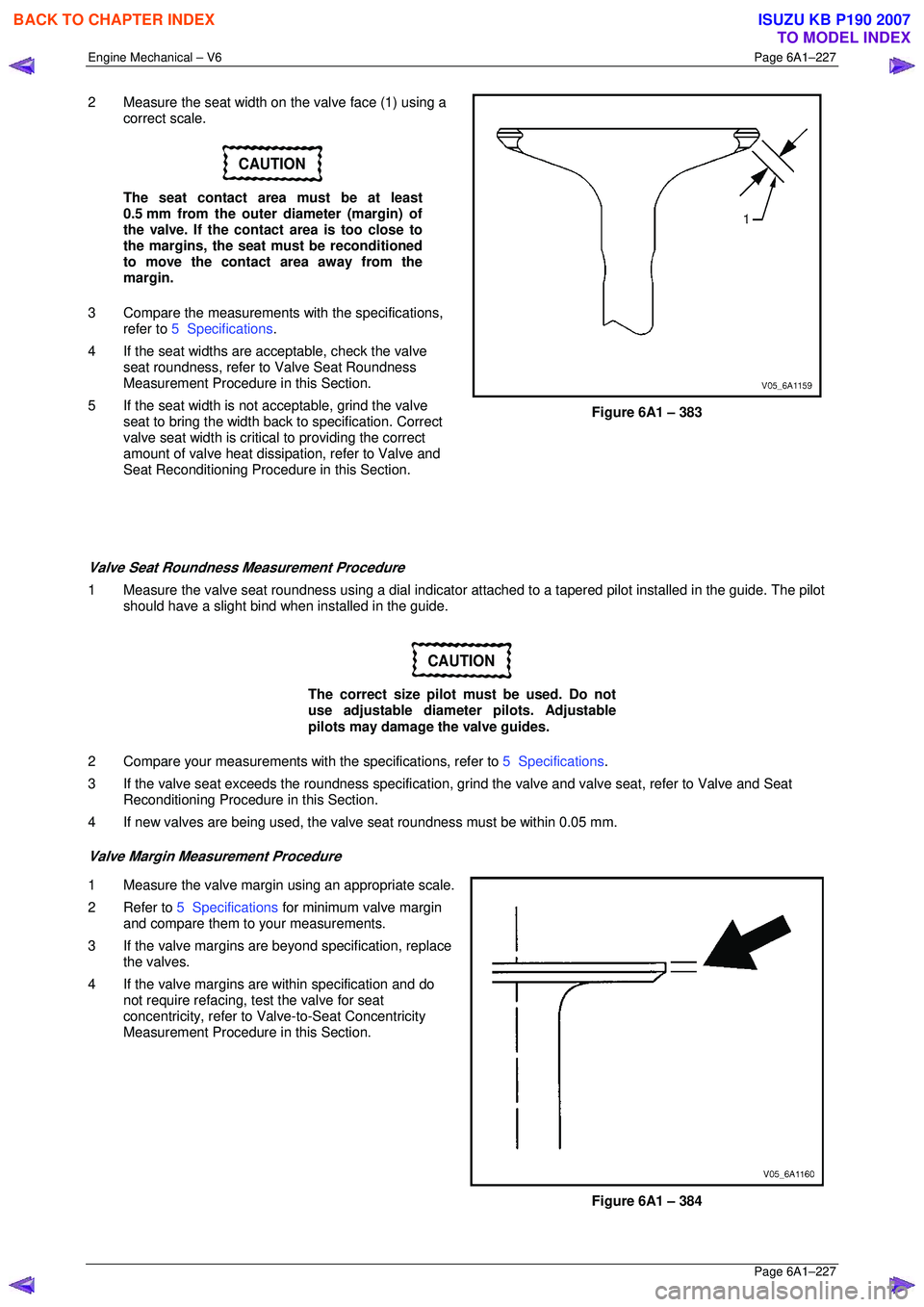
2 Measure the seat width on the valve face (1) using a
correct scale.
CAUTION
The seat contact area must be at least
0.5 mm from the outer diameter (margin) of
the valve. If the contact area is too close to
the margins, the seat must be reconditioned
to move the contact area away from the
margin.
3 Compare the measurements with the specifications,
refer to 5 Specifications .
4 If the seat widths are a cceptable, check the valve
seat roundness, refer to Valve Seat Roundness
Measurement Procedure in this Section.
5 If the seat width is not acceptable, grind the valve
seat to bring the width back to specification. Correct
valve seat width is critical to providing the correct
amount of valve heat dissipat ion, refer to Valve and
Seat Reconditioning Procedure in this Section.
Figure 6A1 – 383
Valve Seat Roundness Measurement Procedure
1 Measure the valve seat roundness using a dial indicator a ttached to a tapered pilot installed in the guide. The pilot
should have a slight bind w hen installed in the guide.
CAUTION
The correct size pilot must be used. Do not
use adjustable diameter pilots. Adjustable
pilots may damage the valve guides.
2 Compare your measurements with the specifications, refer to 5 Specifications.
3 If the valve seat exceeds the roundne ss specification, grind the valve and valve seat, refer to Valve and Seat
Reconditioning Procedure in this Section.
4 If new valves are being used, the valv e seat roundness must be within 0.05 mm.
Valve Margin Measurement Procedure
1 Measure the valve margin using an appropriate scale.
2 Refer to 5 Specifications for minimum valve margin
and compare them to your measurements.
3 If the valve margins are beyond specification, replace the valves.
4 If the valve margins are within specification and do not require refacing, test the valve for seat
concentricity, refer to Valve-to-Seat Concentricity
Measurement Procedure in this Section.
Figure 6A1 – 384
BACK TO CHAPTER INDEX
TO MODEL INDEX
ISUZU KB P190 2007
Page 3010 of 6020

Engine Mechanical – V6 Page 6A1–233
Page 6A1–233
Reinstall
Right-hand Side (Bank 1) Cylinder Head
The reinstallation procedure for the right-hand side cylinder head assembly is the reverse of the removal procedure,
noting the following:
1 Ensure all fasteners are tightened to the correct torque specification.
2 Using crankshaft rotation Tool No. EN-46111 (1), align the crankshaft sprocket timing mark (2) with the
indexing mark (3) on the oil pump housing.
Figure 6A1 – 396
3 Ensure the deck face is clean and the cylinder head locating pins are securely mounted in the cylinder
block deck face.
4 Install a new right-hand cylinder head gasket (1) using the deck face locating pins for retention.
Figure 6A1 – 397
5 Align the cylinder head with the locating pins.
6 Place the cylinder head in position on the deck face.
NOTE
Do not allow oil on the cylinder head bolt
bosses.
CAUTION
Do not reuse the old M11 cylinder head bolts
(1 to 8 inclusive).
7 Install new M11 cylinder head bolts (1) eight places and tighten in the sequence shown and to the correct
torque specification.
Figure 6A1 – 398
BACK TO CHAPTER INDEX
TO MODEL INDEX
ISUZU KB P190 2007
Page 3011 of 6020
Engine Mechanical – V6 Page 6A1–234
Page 6A1–234
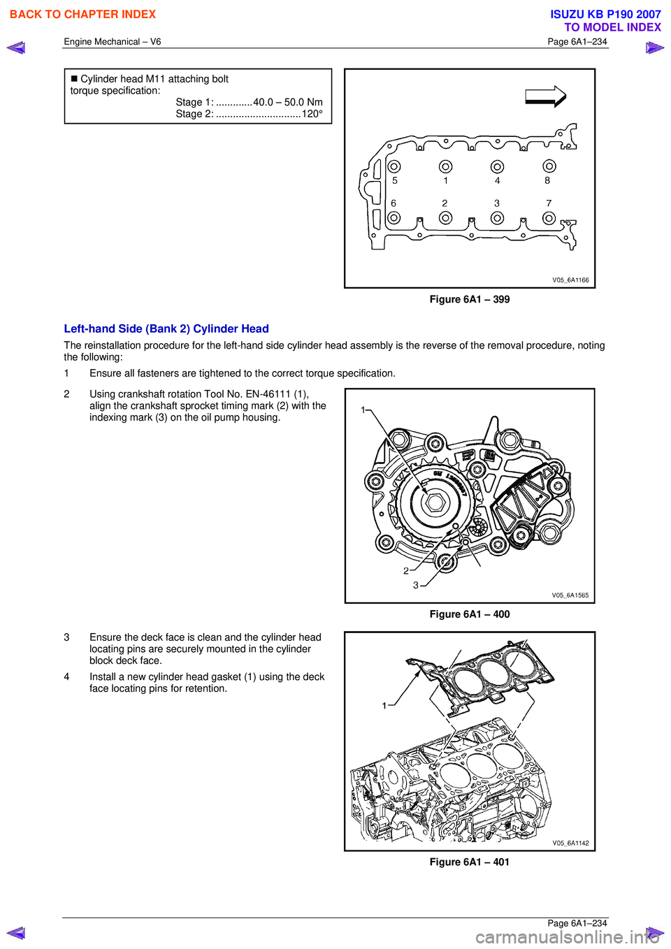
�„ Cylinder head M11 attaching bolt
torque specification:
Stage 1:............. 40.0 – 50.0 Nm
Stage 2:.............................. 120°
Figure 6A1 – 399
Left-hand Side (Bank 2) Cylinder Head
The reinstallation procedure for the left-hand side cylinder head a ssembly is the reverse of the removal procedure, noting
the following:
1 Ensure all fasteners are tightened to the correct torque specification.
2 Using crankshaft rotation Tool No. EN-46111 (1), align the crankshaft sprocket timing mark (2) with the
indexing mark (3) on the oil pump housing.
Figure 6A1 – 400
3 Ensure the deck face is clean and the cylinder head locating pins are securely mounted in the cylinder
block deck face.
4 Install a new cylinder head gasket (1) using the deck face locating pins for retention.
Figure 6A1 – 401
BACK TO CHAPTER INDEX
TO MODEL INDEX
ISUZU KB P190 2007