engine mount ISUZU KB P190 2007 Workshop Repair Manual
[x] Cancel search | Manufacturer: ISUZU, Model Year: 2007, Model line: KB P190, Model: ISUZU KB P190 2007Pages: 6020, PDF Size: 70.23 MB
Page 3156 of 6020
Engine Cooling – V6 Engine Page 6B1–21
Calibrating the Tester
The coolant tester calibration is checked at manufacture. If however, the calibration check detailed in Step 1 of this
method shows that the instrument is not reading correctly, then conduct the following recalibration procedure:
1 Remove the sealant covering the adjustment screw on the underneath of the tester.
2 W ith a distilled water sample on the measuring surface, carefully adjust the screw until a zero reading is obtained.
NOTE
DO NOT completely remove the screw.
3 After recalibration, reseal the screw with a small amount of silicone sealant.
Method 2 – Hydrometer
1 The cooling system should be at or close to ambient temperature.
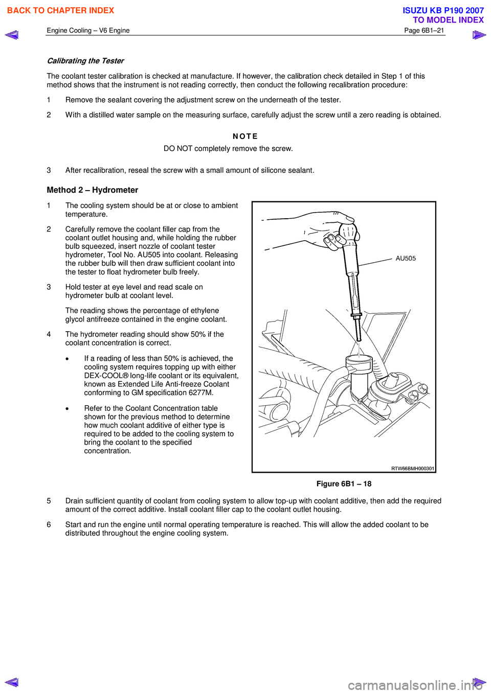
2 Carefully remove the coolant filler cap from the coolant outlet housing and, while holding the rubber
bulb squeezed, insert nozzle of coolant tester
hydrometer, Tool No. AU505 into coolant. Releasing
the rubber bulb will then draw sufficient coolant into
the tester to float hydrometer bulb freely.
3 Hold tester at eye level and read scale on hydrometer bulb at coolant level.
The reading shows the percentage of ethylene glycol antifreeze contained in the engine coolant.
4 The hydrometer reading should show 50% if the coolant concentration is correct.
• If a reading of less than 50% is achieved, the
cooling system requires topping up with either
DEX-COOL® long-life coolant or its equivalent,
known as Extended Life Anti-freeze Coolant
conforming to GM specification 6277M.
• Refer to the Coolant Concentration table
shown for the previous method to determine
how much coolant additive of either type is
required to be added to the cooling system to
bring the coolant to the specified
concentration.
Figure 6B1 – 18
5 Drain sufficient quantity of coolant from cooling system to allow top-up with coolant additive, then add the required amount of the correct additive. Install coolant filler cap to the coolant outlet housing.
6 Start and run the engine until normal operating temperature is reached. This will allow the added coolant to be distributed throughout the engine cooling system.
BACK TO CHAPTER INDEX
TO MODEL INDEX
ISUZU KB P190 2007
Page 3163 of 6020
Engine Cooling – V6 Engine Page 6B1–28
3.5 Drive Belt Tension
An automatic tensioner assembly provides drive belt tension. The tensioner is an idler pulley mounted on a spring-loaded
arm that maintains the drive belt at the proper tension, without imposing undue loads on the various components.
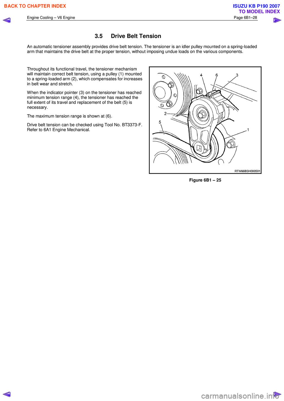
Throughout its functional travel, the tensioner mechanism
will maintain correct belt tension, using a pulley (1) mounted
to a spring-loaded arm (2), which compensates for increases
in belt wear and stretch.
W hen the indicator pointer (3) on the tensioner has reached
minimum tension range (4), the tensioner has reached the
full extent of its travel and replacement of the belt (5) is
necessary.
The maximum tension range is shown at (6).
Drive belt tension can be checked using Tool No. BT3373-F.
Refer to 6A1 Engine Mechanical.
Figure 6B1 – 25
BACK TO CHAPTER INDEX
TO MODEL INDEX
ISUZU KB P190 2007
Page 3190 of 6020
Engine Cooling – V6 Engine Page 6B1–55
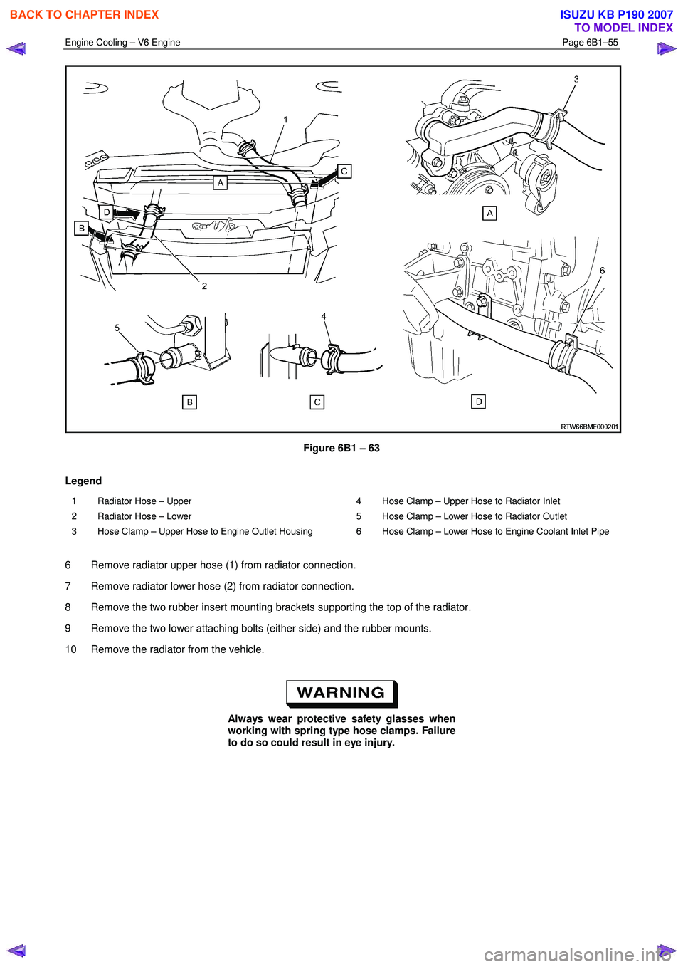
Figure 6B1 – 63
Legend
1 Radiator Hose – Upper
2 Radiator Hose – Lower
3 Hose Clamp – Upper Hose to Engine Outlet Housing 4 Hose Clamp – Upper Hose to Radiator Inlet
5 Hose Clamp – Lower Hose to Radiator Outlet
6 Hose Clamp – Lower Hose to Engine Coolant Inlet Pipe
6 Remove radiator upper hose (1) from radiator connection.
7 Remove radiator lower hose (2) from radiator connection.
8 Remove the two rubber insert mounting brackets supporting the top of the radiator.
9 Remove the two lower attaching bolts (either side) and the rubber mounts.
10 Remove the radiator from the vehicle.
Always wear protective safety glasses when
working with spring type hose clamps. Failure
to do so could result in eye injury.
BACK TO CHAPTER INDEX
TO MODEL INDEX
ISUZU KB P190 2007
Page 3194 of 6020
Engine Cooling – V6 Engine Page 6B1–59
General Core Repair
NOTE
The need for careful preparation of the surface in
the repair area cannot be over-emphasised. If the
leak area surface is not clean, the repair material
will not adhere to the surface.
Refer to ‘
‘‘
‘
Environmental Issues ’
’’
’
in 3.1
Service Notes, before draining the coolant.
1 Drain the coolant from the system. Refer to 3.3 Draining and Filling Cooling System in this Section.
2 Remove the radiator. Refer to 3.15 Radiator in this Section.
3 If necessary, carefully cut away fins to expose the damaged area.
NOTE
Do not cut away more than 25 mm total fin
material.
4 Clean away dirt etc. with water. Dry the affected area using hot air from a hair drier.
Do not apply flame to dry damaged area.
5 Clean affected area with petrol to remove any traces of oil.
6 Thoroughly stir contents of repair agent.
NOTE
In cases of extended shelf life, the silicon in
solution may separate from the thinner base.
Should this occur, mix contents well until agent is
again homogeneous.
7 Apply repair agent sparingly to damaged area. Do not apply an excessive amount, as this will cause blockage of the radiator tube.
NOTE
Use a clean, dry wooden applicator to 'DRIP'
agent onto damaged area of radiator.
8 Allow radiator to stand in a clean, dry area for a minimum of 3 hours (at ambient temperature of 20 – 30 ° C) with
adequate ventilation.
NOTE
Do not apply heat or flame to promote drying.
9 Reinstall the radiator. Refer to 3.15 Radiator in this Section.
BACK TO CHAPTER INDEX
TO MODEL INDEX
ISUZU KB P190 2007
Page 3196 of 6020
Engine Cooling – V6 Engine Page 6B1–61
4 Engine Cooling System
Diagnosis
4.1 Poor Heater Operation
Little or no heat coming from the heater, especially at idle could be an indication of a cooling system problem.
As the coolant level begins to get lower than normal, air enters the system to replace the missing coolant. The heater
core is one of the highest parts of the cooling system and therefore, the first area to lose coolant circulation.
At first, with a small amount of coolant loss, lack of heat will be most noticeable at idle. As driving speed increases, the
engine pumps more coolant and more heat is now able to pass through the heater core.
If coolant level drops even lower, heater operation will become less effective, even during normal driving. Cooling and
engine systems can be adversely affected if problem is not corrected before overheating occurs.
4.2 Leaking Cylinder Head Gasket
Combustion gases leaking past the cylinder head gasket can pressurise the cooling system, forcing coolant out of the
system and into the coolant recovery reservoir.
Indications are air bubbles in the coolant or an overflow condition of the recovery reservoir.
4.3 Question the Customer
To avoid needless time and cost in diagnosing cooling system complaints, the customer should be questioned about
driving conditions that place abnormal loads on the cooling system.
1 Is overheating occurring after prolonged idle, in gear, with air conditioning system operating?
If answer is YES – instruct owner on driving techniques that would avoid overheating such as:
• Idle in neutral as much as possible – increase engine rpm to get higher air flow (due to an increase in voltage
to the fan) and coolant flow through the radiator
• Turn air conditioning system off during extended idling periods if overheating is indicated on temperature
gauge. Further diagnostic checks should not be required
2 Is overheating occurring after prolonged driving in slow city traffic, traffic jams, parades, etc?
If answer is YES, explain driving technique to the customer, that would avoid overheating – same as for prolonged idle – No.1. Further diagnostic checks should not be required.
4.4 Diagnostic Chart
If none of the above conditions apply, refer to the following Diagnosis Chart.
To effectively use this chart, question the customer to determine which of the following three categories apply to the
complaint:
1 If complaint is hot indication on temperature gauge.
W as temperature reading accompanied by boiling?
• If answer is YES, go to overheating on diagnosis chart
• If answer is NO, check temperature gauge and sender
2 If complaint is boiling – go to overheating on diagnosis chart.
3 If complaint is coolant loss. Determine if customer is filling the system correctly.
4 If incorrect filling is not the problem, go to coolant loss in the diagnosis chart.
BACK TO CHAPTER INDEX
TO MODEL INDEX
ISUZU KB P190 2007
Page 3198 of 6020
Engine Cooling – V6 Engine Page 6B1–63
4.5 Problems Not Requiring Disassembly of
Cooling System
1 Large obstructions blocking radiator or condenser airflow.
• Auxiliary oil coolers
• License plate
• Obstruction of radiator grille, for example, driving lights or mud
2 Loose, damaged or missing air chute side panels.
3 Missing or damaged air baffle.
4 Cracked or loose coolant recovery system hose.
5 Leaking heater component such as the heater core or water valve.
4.6 Problems Requiring Disassembly of Cooling System
1 Damaged cooling fan or faulty motor operation.
2 Pressure test cooling system.
3 Defective coolant pump.
• Eroded or broken impeller vanes
• Failed bearing or seal – check for shaft or bearing end play
4 Internally blocked radiator core.
5 Obstruction of coolant recovery system.
6 Internal system leaks.
• Head gaskets
• Cracked cylinder block
• Engine front cover
• Intake manifold gaskets
7 Blocked coolant passages in cylinder heads or block – remove cylinder heads and check.
4.7 Black Light and Dye Leak Diagnosis Method
It is strongly recommended that this diagnostic method be used to diagnose fluid leaks. This method is a proven and
reliable method that identifies the specific leak source.
The black light kit can be used for the leak detection of a number of fluids, when used with the appropriate tracer dye.
Examples are: Coolant, Engine Oil, Automatic Transmission Fluid and Air Conditioning Refrigerant (R134A).
The following is a summary of the steps involved in detecting a cooling system fluid leak using black light and dye:
1 Pour specified amount of dye into the cooling system via the coolant filler cap on the outlet housing. Refer 3.1 Service Notes in this Section.
2 Road test the vehicle under normal operating conditions.
3 Direct the light towards the suspect area. The fluid leak will appear as a brightly coloured path leading from the source.
4 Repair fluid leak and recheck to ensure that leak has been rectified.
5 Refer to the manufacturer’s directions when using this method.
BACK TO CHAPTER INDEX
TO MODEL INDEX
ISUZU KB P190 2007
Page 3205 of 6020
Fuel System – V6 Page 6C – 3
1 General Information
Description
Fuel is injected into the engine by separate fuel injectors that are mounted in the intake manifold (common chamber).
Fuel is supplied to the injectors under pressure from the fuel tank through the fuel lines and the fuel rail, which is
attached to the top of the common chamber.
A fuel pressure control valve is installed on the fuel rail to maintain fuel line pressure across the injectors under all
operating conditions. Fuel pressure is maintained by controlling the amount of fuel that is supplied from the fuel tank,
based on the demand of the engine via the engine control module (ECM).
Two interchangeable “O” rings are used on the fuel injector and must be replaced when the injectors are removed.
The Multiport Fuel Injection system utilizes an injection system where the injectors turn on at every crankshaft revolution.
The ECM controls the injector on time so that the correct amount of fuel is metered depending on driving conditions.
The V6 engine is designed to use only unleaded petrol.
Unleaded petrol must be used for correct emission control system operation and its use will also minimize spark plug
fouling and extend engine oil life.
Using leaded petrol can damage the emission control system and could void the vehicle warranty. All vehicles are
equipped with an Evaporative Emission Control System. The purpose of the system is to minimize the escape of fuel
vapours into the atmosphere.
Service Precautions
• Use extreme care when working on the fuel system and follow all safety precautions.
• W hen working on the fuel system, disconnect the battery ground cable except for tests where battery voltage is
required.
• Always keep a dry chemical (class B) fire extinguisher near the work area.
• Relace all fuel lines and fittings with the same type of line and fitting as those removed.
• Clean and inspect “O” rings carefully and replace if required.
• Always depressurize the fuel lines before servicing any fuel system components.
• Do not attempt any repairs on the fuel system until, all warnings and instructions, relating to that repair have been
read and ensure all notices and cautions are adhered to.
• Do not allow any naked frames or sparks near the work area when working on the fuel system.
• If draining of the fuel system is required, this should be done in a well ventilated area.
• Protect the fuel lines and associated parts from thermal damage, spattering when welding.
BACK TO CHAPTER INDEX
TO MODEL INDEX
ISUZU KB P190 2007
Page 3209 of 6020
Fuel System – V6 Page 6C – 7
Fuel Flow
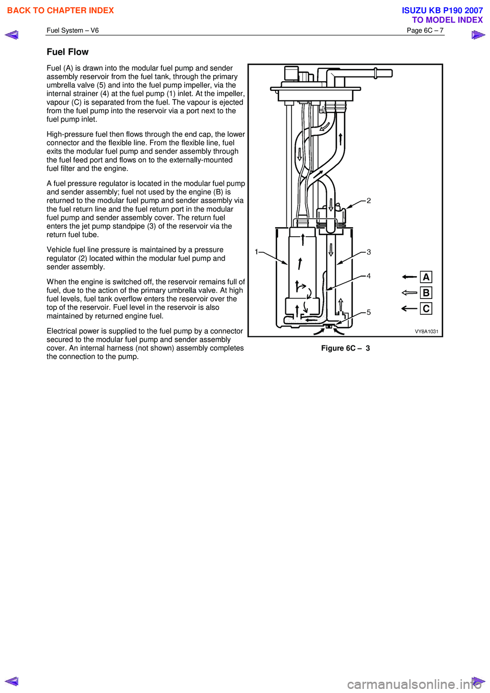
Fuel (A) is drawn into the modular fuel pump and sender
assembly reservoir from the fuel tank, through the primary
umbrella valve (5) and into the fuel pump impeller, via the
internal strainer (4) at the fuel pump (1) inlet. At the impeller,
vapour (C) is separated from the fuel. The vapour is ejected
from the fuel pump into the reservoir via a port next to the
fuel pump inlet.
High-pressure fuel then flows through the end cap, the lower
connector and the flexible line. From the flexible line, fuel
exits the modular fuel pump and sender assembly through
the fuel feed port and flows on to the externally-mounted
fuel filter and the engine.
A fuel pressure regulator is located in the modular fuel pump
and sender assembly; fuel not used by the engine (B) is
returned to the modular fuel pump and sender assembly via
the fuel return line and the fuel return port in the modular
fuel pump and sender assembly cover. The return fuel
enters the jet pump standpipe (3) of the reservoir via the
return fuel tube.
Vehicle fuel line pressure is maintained by a pressure
regulator (2) located within the modular fuel pump and
sender assembly.
W hen the engine is switched off, the reservoir remains full of
fuel, due to the action of the primary umbrella valve. At high
fuel levels, fuel tank overflow enters the reservoir over the
top of the reservoir. Fuel level in the reservoir is also
maintained by returned engine fuel.
Electrical power is supplied to the fuel pump by a connector
secured to the modular fuel pump and sender assembly
cover. An internal harness (not shown) assembly completes
the connection to the pump.
Figure 6C – 3
BACK TO CHAPTER INDEX
TO MODEL INDEX
ISUZU KB P190 2007
Page 3211 of 6020
Fuel System – V6 Page 6C – 9
A small amount of fuel may be released when
connecting the fuel pressure gauge to the fuel
pressure test point. Cover the fittings with a
shop towel to absorb any fuel spillage before
connecting the fuel pressure gauge. After the
fuel pressure test procedure, place the soiled
towel in an approved container for disposal.
3 At the fuel pressure test point, remove the Schrader valve sealing cap.
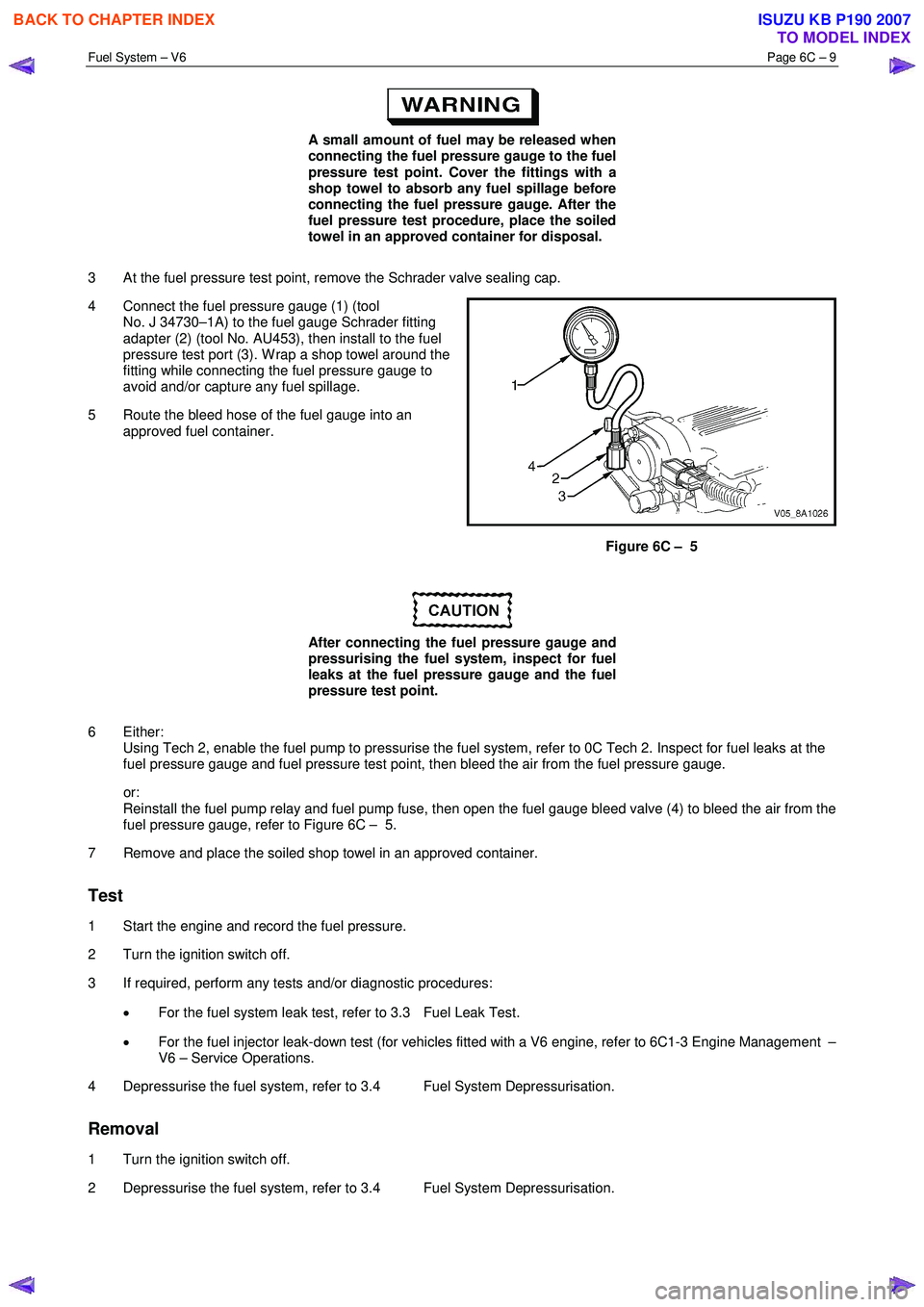
4 Connect the fuel pressure gauge (1) (tool No. J 34730–1A) to the fuel gauge Schrader fitting
adapter (2) (tool No. AU453), then install to the fuel
pressure test port (3). W rap a shop towel around the
fitting while connecting the fuel pressure gauge to
avoid and/or capture any fuel spillage.
5 Route the bleed hose of the fuel gauge into an approved fuel container.
Figure 6C – 5
After connecting the fuel pressure gauge and
pressurising the fuel system, inspect for fuel
leaks at the fuel pressure gauge and the fuel
pressure test point.
6 Either: Using Tech 2, enable the fuel pump to pressurise the fuel system, refer to 0C Tech 2. Inspect for fuel leaks at the
fuel pressure gauge and fuel pressure test point, then bleed the air from the fuel pressure gauge.
or: Reinstall the fuel pump relay and fuel pump fuse, then open the fuel gauge bleed valve (4) to bleed the air from the
fuel pressure gauge, refer to Figure 6C – 5.
7 Remove and place the soiled shop towel in an approved container.
Test
1 Start the engine and record the fuel pressure.
2 Turn the ignition switch off.
3 If required, perform any tests and/or diagnostic procedures:
• For the fuel system leak test, refer to 3.3 Fuel Leak Test.
• For the fuel injector leak-down test (for vehicles fitted with a V6 engine, refer to 6C1-3 Engine Management –
V6 – Service Operations.
4 Depressurise the fuel system, refer to 3.4 Fuel System Depressurisation.
Removal
1 Turn the ignition switch off.
2 Depressurise the fuel system, refer to 3.4 Fuel System Depressurisation.
BACK TO CHAPTER INDEX
TO MODEL INDEX
ISUZU KB P190 2007
Page 3212 of 6020
Fuel System – V6 Page 6C – 10
After relieving the fuel system pressure, a
small amount of fuel may be released when
servicing the fuel lines or connections. Cover
the fittings with a shop towel before
disconnecting. This catches any leaking fuel.
Place the soiled towel in an approved
container when disconnection is completed.
3 W rap a shop towel around the fuel pressure test point to absorb any fuel spillage.
4 Remove the fuel pressure gauge and drain any fuel remaining in the fuel pressure gauge into an approved fuel container.
5 Remove the soiled shop towel and place in an approved container.
6 Repressurise the fuel system, refer to 3.4 Fuel System Depressurisation.
7 Road-test the vehicle and check for correct operation.
3.3 Fuel Leak Test
After installing any fuel system component
and before starting the engine, check the fuel
system for leaks.
NOTE
For the fuel injector leak-down test (for vehicles
fitted with a V6 engine), refer to 6C1-3 Engine
Management – V6 – Service Operations.
1 Turn the ignition switch on for two seconds.
2 Turn the ignition switch off for 10 seconds.
3 Turn the ignition switch on.
4 Check for fuel leaks, particularly at points marked �z (that is, quick-connect fittings, fuel rails, fuel injectors,
Schrader valve and evaporative emission control canister purge solenoid, refer to Figure 6C – 6.
BACK TO CHAPTER INDEX
TO MODEL INDEX
ISUZU KB P190 2007