ISUZU KB P190 2007 Workshop Repair Manual
Manufacturer: ISUZU, Model Year: 2007, Model line: KB P190, Model: ISUZU KB P190 2007Pages: 6020, PDF Size: 70.23 MB
Page 2961 of 6020
Engine Mechanical – V6 Page 6A1–184
Page 6A1–184
4 Inspect the outer driven gear for damage.
Figure 6A1 – 294
5 Inspect the oil pump relief valve components for debris or damage.
Figure 6A1 – 295
6 Inspect the primary camshaft chain lower guide for damage. If replacement of t he primary camshaft chain
lower guide is required, r eplace the entire oil pump
assembly as the primary camshaft chain lower guide
is not serviceable separately.
7 If debris or damage is pres ent within the oil pump,
further inspection of all of the engine components is
required.
Figure 6A1 – 296
BACK TO CHAPTER INDEX
TO MODEL INDEX
ISUZU KB P190 2007
Page 2962 of 6020
Engine Mechanical – V6 Page 6A1–185
Page 6A1–185
Reassemble
CAUTION
As there are no serviceable components
within the oil pump, a disassembled oil pump
must be replaced.
Reinstall
1 Align the oil pump gerotor with the crankshaft flats
and fit the oil pump assembly to the engine block.
2 Align the pump body (2) with the mounting holes in the cylinder block.
3 Install the oil pump bolt (1), three places, and tighten to the correct torque specification.
4 Install the primary timing chain, refer to 3.16 Timing
Chains, Tensioners, Shoes and Guides .
Oil pump attaching bolt torque
specificat ion ............................................ 20.0 – 26.0 Nm
Figure 6A1 – 297
BACK TO CHAPTER INDEX
TO MODEL INDEX
ISUZU KB P190 2007
Page 2963 of 6020

Engine Mechanical – V6 Page 6A1–186
Page 6A1–186
3.18 Camshaft Sprocket – Excluding MY06
Update
CAUTION
Setting the camshaft timing is required
whenever the camshaft drive system is
disturbed to ensure the relationship between
any chain and sprocket is not lost. Even when
only one sprocket is involved, multiple
crankshaft rotations will not produce
conditions where correct timing can be
confirmed.
If required, follow the Left-hand Secondary
Camshaft Chain Components reinstallation
procedure to reset the camshaft timing.
Remove
Right-hand Side
1 Remove the right-hand ca mshaft cover, refer to 3.12 Camshaft Cover.
2 Remove the camshaft position sensors, refer to Section 6C1-3 Engine Management – Service Operations.
3 Remove the camshaft position actuator solenoids, refer to Section 6C1-3 Engine Management – V6 – Service
Operations .
4 Remove the crankshaft bal ancer assembly, refer to 3.13 Crankshaft Balancer Assembly .
5 Install the crankshaft rotation socket Tool No. EN-46111 onto the crankshaft.
6 Rotate the crankshaft until the camshafts are in a neutral low tension position. The camshaft flats will be
parallel with the camshaft cover rail (1).
Figure 6A1 – 298
BACK TO CHAPTER INDEX
TO MODEL INDEX
ISUZU KB P190 2007
Page 2964 of 6020
Engine Mechanical – V6 Page 6A1–187
Page 6A1–187
7 Install Tool No. EN-46105 – 1 (1) onto the rear of the
right-hand cylinder head (3) camshafts (2).
Figure 6A1 – 299
NOTE
Use an open-end spanner (1) at the camshaft
hex (2) to prevent camshaft/engine rotation.
NOTE
Do not remove the cams haft sprocket bolt (3) at
this time.
8 Loosen the camshaft sprocket bolt (3). NOTE
If you have already removed the camshaft
timing chain proceed to step 12
Figure 6A1 – 300
BACK TO CHAPTER INDEX
TO MODEL INDEX
ISUZU KB P190 2007
Page 2965 of 6020
Engine Mechanical – V6 Page 6A1–188
Page 6A1–188
CAUTION
Ensure the tips of Tool No.
EN-46108 are fully engaged into the timing
chain and the wing nuts are tight and the
timing chain is taught.
9 Install Tool No. EN-46108 (1 and 2) to retain the timing chain (3 and 4).
10 Firmly tighten the wing nuts of Tool No. EN-46108.
11 Mark the timing chain and the respective location on both camshaft sprocket.
NOTE
Ensure the camshaft timing chain and the
camshaft sprocket are marked for correct
reassembly.
Figure 6A1 – 301
12 Remove the bolt (1) attaching the right-hand exhaust camshaft sprocket (2) and remove the sprocket.
Figure 6A1 – 302
13 Remove the bolt (1) attaching right-hand intake camshaft sprocket (2) and remove the sprocket.
Figure 6A1 – 303
BACK TO CHAPTER INDEX
TO MODEL INDEX
ISUZU KB P190 2007
Page 2966 of 6020

Engine Mechanical – V6 Page 6A1–189
Page 6A1–189
Left-hand Side
1 Remove the left-hand camshaft cover, refer to 3.12 Camshaft Cover .
2 Remove the camshaft position sensors, refer to Section 6C1-3 Engine Management – V6 – Service Operations.
3 Remove the camshaft position actuator solenoids, refer to Section 6C1-3 Engine Management – V6 – Service
Operations .
4 Remove the crankshaft bal ancer assembly, refer to 3.13 Crankshaft Balancer Assembly .
5 Install the crankshaft rotation socket Tool No. EN-46111 onto the crankshaft.
6 Rotate the crankshaft until the camshafts are in a neutral low tension position. The camshaft flats will be
parallel with the camshaft cover rail (1).
Figure 6A1 – 304
7 Install Tool No. EN-46105 – 1 (1) onto the rear of the
left-hand cylinder head camshafts (2).
Figure 6A1 – 305
BACK TO CHAPTER INDEX
TO MODEL INDEX
ISUZU KB P190 2007
Page 2967 of 6020
Engine Mechanical – V6 Page 6A1–190
Page 6A1–190
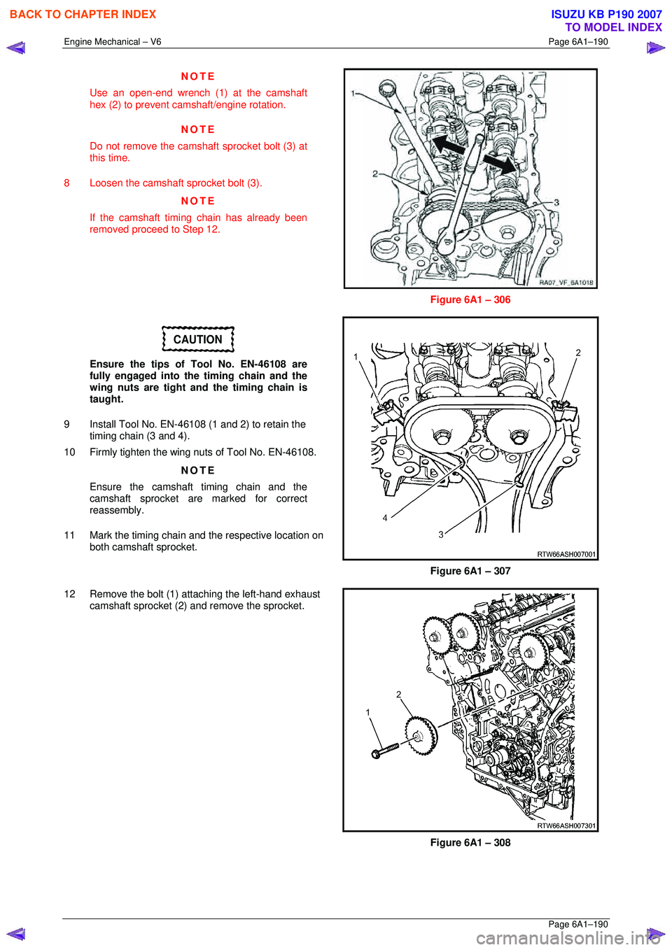
NOTE
Use an open-end wrench (1) at the camshaft
hex (2) to prevent camshaft/engine rotation.
NOTE
Do not remove the cams haft sprocket bolt (3) at
this time.
8 Loosen the camshaft sprocket bolt (3). NOTE
If the camshaft timing chain has already been
removed proceed to Step 12.
Figure 6A1 – 306
CAUTION
Ensure the tips of Tool No. EN-46108 are
fully engaged into the timing chain and the
wing nuts are tight and the timing chain is
taught.
9 Install Tool No. EN-46108 (1 and 2) to retain the timing chain (3 and 4).
10 Firmly tighten the wing nuts of Tool No. EN-46108.
NOTE
Ensure the camshaft timing chain and the
camshaft sprocket are marked for correct
reassembly.
11 Mark the timing chain and the respective location on both camshaft sprocket.
Figure 6A1 – 307
12 Remove the bolt (1) attaching the left-hand exhaust camshaft sprocket (2) and remove the sprocket.
Figure 6A1 – 308
BACK TO CHAPTER INDEX
TO MODEL INDEX
ISUZU KB P190 2007
Page 2968 of 6020
Engine Mechanical – V6 Page 6A1–191
Page 6A1–191
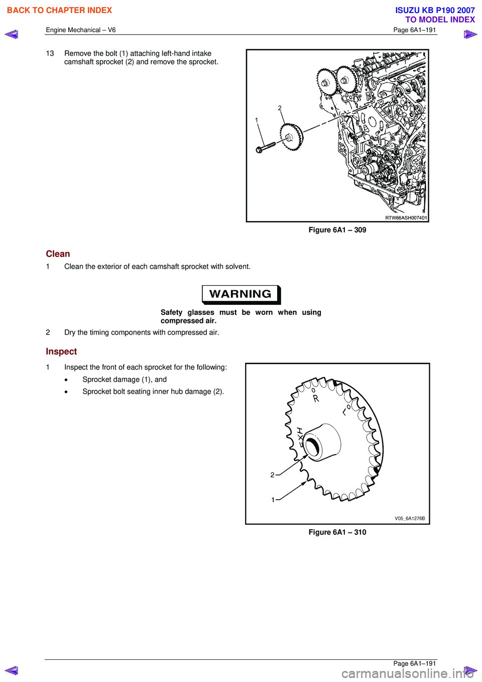
13 Remove the bolt (1) attaching left-hand intake
camshaft sprocket (2) and remove the sprocket.
Figure 6A1 – 309
Clean
1 Clean the exterior of each ca mshaft sprocket with solvent.
Safety glasses must be worn when using
compressed air.
2 Dry the timing components with compressed air.
Inspect
1 Inspect the front of each sprocket for the following:
• Sprocket damage (1), and
• Sprocket bolt seating inner hub damage (2).
Figure 6A1 – 310
BACK TO CHAPTER INDEX
TO MODEL INDEX
ISUZU KB P190 2007
Page 2969 of 6020
Engine Mechanical – V6 Page 6A1–192
Page 6A1–192
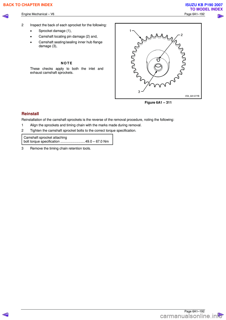
2 Inspect the back of each sprocket for the following:
• Sprocket damage (1),
• Camshaft locating pin damage (2) and,
• Camshaft seating/sealing inner hub flange
damage (3),
NOTE
These checks apply to both the inlet and
exhaust camshaft sprockets.
Figure 6A1 – 311
Reinstall
Reinstallation of the camshaft sprocke ts is the reverse of the removal procedure, noting the following:
1 Align the sprockets and timing chain with the marks made during removal.
2 Tighten the camshaft sprocket bolts to the correct torque specification.
Camshaft sprocket attaching
bolt torque specificat ion .......................... 49.0 – 67.0 Nm
3 Remove the timing chain retention tools.
BACK TO CHAPTER INDEX
TO MODEL INDEX
ISUZU KB P190 2007
Page 2970 of 6020

Engine Mechanical – V6 Page 6A1–193
Page 6A1–193
3.19 Camshaft Sprocket – MY06 Update
CAUTION
Setting the camshaft timing is required
whenever the camshaft drive system is
disturbed to ensure the relationship between
any chain and sprocket is not lost. Even when
only one sprocket is involved, multiple
crankshaft rotations will not produce
conditions where correct timing can be
confirmed.
If required, follow the Left-hand Secondary
Camshaft Chain Components reinstallation
procedure to reset the camshaft timing.
Remove
Right-hand Side
1 Remove the right-hand camshaft cover, refer to 3.12 Camshaft Cover.
2 Remove the camshaft position sensors, refer to Section 6C1-3 Engine Management – Service Operations.
3 Remove the camshaft position actuator solenoids, refer to Section 6C1-3 Engine Management – V6 – Service
Operations .
4 Remove the crankshaft bal ancer assembly, refer to 3.13 Crankshaft Balancer Assembly .
5 Install the crankshaft rotation socket Tool No. EN-46111 onto the crankshaft.
6 Rotate the crankshaft until the camshafts are in a neutral low tension position. The camshaft flats will be
parallel with the camshaft cover rail (1).
Figure 6A1 – 312
BACK TO CHAPTER INDEX
TO MODEL INDEX
ISUZU KB P190 2007