ISUZU KB P190 2007 Workshop Repair Manual
Manufacturer: ISUZU, Model Year: 2007, Model line: KB P190, Model: ISUZU KB P190 2007Pages: 6020, PDF Size: 70.23 MB
Page 2971 of 6020
Engine Mechanical – V6 Page 6A1–194
Page 6A1–194
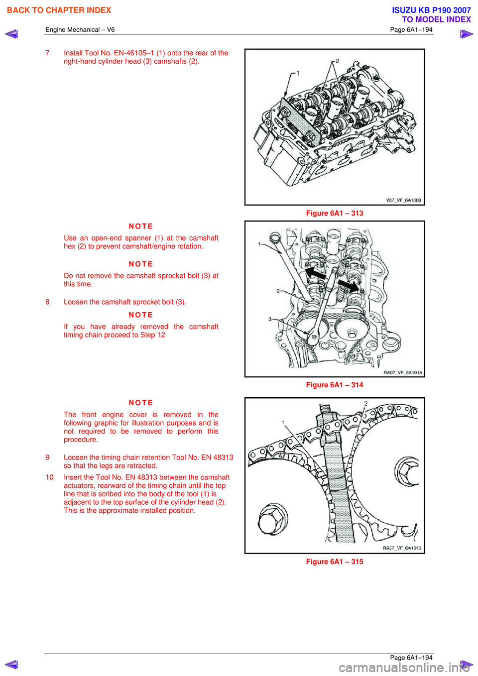
7 Install Tool No. EN-46105–1 (1) onto the rear of the
right-hand cylinder head (3) camshafts (2).
Figure 6A1 – 313
NOTE
Use an open-end spanner (1) at the camshaft
hex (2) to prevent camshaft/engine rotation.
NOTE
Do not remove the cams haft sprocket bolt (3) at
this time.
8 Loosen the camshaft sprocket bolt (3). NOTE
If you have already removed the camshaft
timing chain proceed to Step 12
Figure 6A1 – 314
NOTE
The front engine cover is removed in the
following graphic for illustration purposes and is
not required to be removed to perform this
procedure.
9 Loosen the timing chain retention Tool No. EN 48313 so that the legs are retracted.
10 Insert the Tool No. EN 48313 between the camshaft actuators, rearward of t he timing chain until the top
line that is scribed into t he body of the tool (1) is
adjacent to the top surfac e of the cylinder head (2).
This is the approximat e installed position.
Figure 6A1 – 315
BACK TO CHAPTER INDEX
TO MODEL INDEX
ISUZU KB P190 2007
Page 2972 of 6020
Engine Mechanical – V6 Page 6A1–195
Page 6A1–195
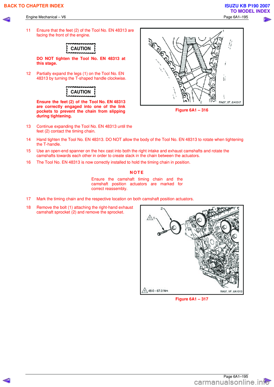
11 Ensure that the feet (2) of the Tool No. EN 48313 are
facing the front of the engine.
CAUTION
DO NOT tighten the Tool No. EN 48313 at
this stage.
12 Partially expand the legs (1) on the Tool No. EN 48313 by turning the T-shaped handle clockwise.
CAUTION
Ensure the feet (2) of the Tool No. EN 48313
are correctly engaged into one of the link
pockets to prevent the chain from slipping
during tightening.
13 Continue expanding the Tool No. EN 48313 until the feet (2) contact the timing chain.
Figure 6A1 – 316
14 Hand tighten the Tool No. EN 48313. DO NOT allow the body of the Tool No. EN 48313 to rotate when tightening
the T-handle.
15 Use an open-end spanner on the hex cast into both the right intake and exhaust camshafts and rotate the
camshafts towards each other in order to creat e slack in the chain between the actuators.
16 The Tool No. EN 48313 is now correctly inst alled to hold the timing chain in position.
NOTE
Ensure the camshaft timing chain and the
camshaft position actuators are marked for
correct reassembly.
17 Mark the timing chain and the respective location on both camshaft position actuators.
18 Remove the bolt (1) attaching the right-hand exhaust camshaft sprocket (2) and remove the sprocket.
Figure 6A1 – 317
BACK TO CHAPTER INDEX
TO MODEL INDEX
ISUZU KB P190 2007
Page 2973 of 6020

Engine Mechanical – V6 Page 6A1–196
Page 6A1–196
19 Remove the bolt (1) attaching right-hand intake
camshaft sprocket (2) and remove the sprocket.
Figure 6A1 – 318
Left-hand Side
1 Remove the left-hand cams haft cover, refer to 3.12 Camshaft Cover .
2 Remove the camshaft position sensors, refer to Section 6C1-3 Engine Management – V6 – Service Operations.
3 Remove the camshaft position actuator solenoids, refer to Section 6C1-3 Engine Management – V6 – Service
Operations .
4 Remove the crankshaft bal ancer assembly, refer to 3.13 Crankshaft Balancer Assembly .
5 Install the crankshaft rotation socket Tool No. EN-46111 onto the crankshaft.
6 Rotate the crankshaft until the camshafts are in a neutral low tension position. The camshaft flats will be
parallel with the camshaft cover rail (1).
Figure 6A1 – 319
BACK TO CHAPTER INDEX
TO MODEL INDEX
ISUZU KB P190 2007
Page 2974 of 6020
Engine Mechanical – V6 Page 6A1–197
Page 6A1–197
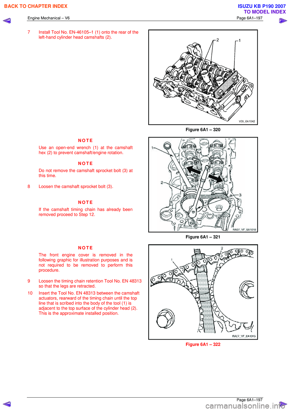
7 Install Tool No. EN-46105–1 (1) onto the rear of the
left-hand cylinder head camshafts (2).
Figure 6A1 – 320
NOTE
Use an open-end wrench (1) at the camshaft
hex (2) to prevent camshaft/engine rotation.
NOTE
Do not remove the cams haft sprocket bolt (3) at
this time.
8 Loosen the camshaft sprocket bolt (3).
NOTE
If the camshaft timing chain has already been
removed proceed to Step 12.
Figure 6A1 – 321
NOTE
The front engine cover is removed in the
following graphic for illustration purposes and is
not required to be removed to perform this
procedure.
9 Loosen the timing chain retention Tool No. EN 48313 so that the legs are retracted.
10 Insert the Tool No. EN 48313 between the camshaft actuators, rearward of t he timing chain until the top
line that is scribed into t he body of the tool (1) is
adjacent to the top surfac e of the cylinder head (2).
This is the approximat e installed position.
Figure 6A1 – 322
BACK TO CHAPTER INDEX
TO MODEL INDEX
ISUZU KB P190 2007
Page 2975 of 6020
Engine Mechanical – V6 Page 6A1–198
Page 6A1–198
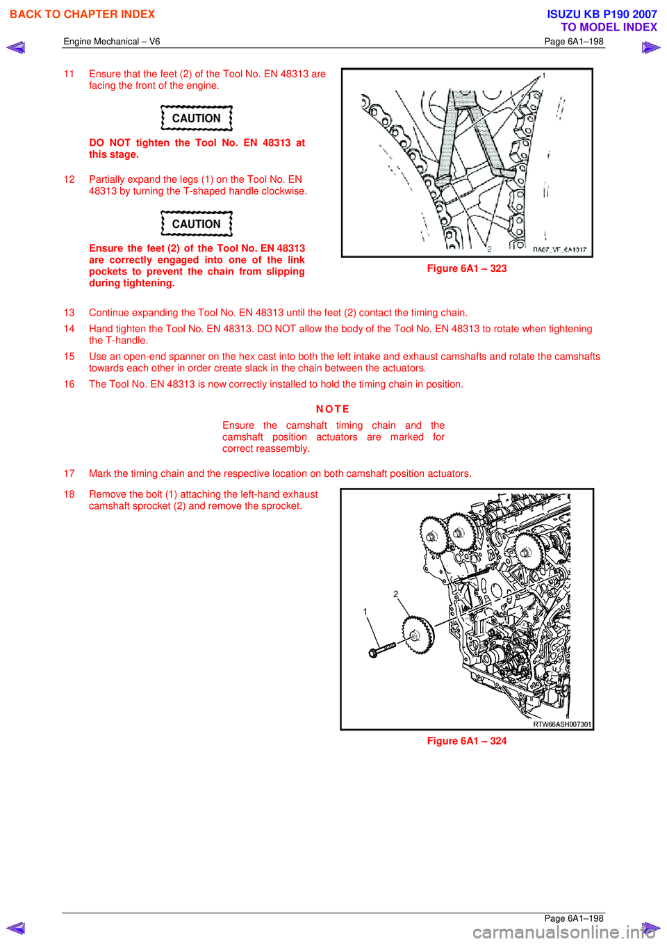
11 Ensure that the feet (2) of the Tool No. EN 48313 are
facing the front of the engine.
CAUTION
DO NOT tighten the Tool No. EN 48313 at
this stage.
12 Partially expand the legs (1) on the Tool No. EN 48313 by turning the T-shaped handle clockwise.
CAUTION
Ensure the feet (2) of the Tool No. EN 48313
are correctly engaged into one of the link
pockets to prevent the chain from slipping
during tightening.
Figure 6A1 – 323
13 Continue expanding the Tool No. EN 48313 until the feet (2) contact the timing chain.
14 Hand tighten the Tool No. EN 48313. DO NOT allow the body of the Tool No. EN 48313 to rotate when tightening
the T-handle.
15 Use an open-end spanner on the hex cast into both the left intake and exhaust camshafts and rotate the camshafts
towards each other in order create sla ck in the chain between the actuators.
16 The Tool No. EN 48313 is now correctly inst alled to hold the timing chain in position.
NOTE
Ensure the camshaft timing chain and the
camshaft position actuators are marked for
correct reassembly.
17 Mark the timing chain and the respective location on both camshaft position actuators.
18 Remove the bolt (1) attaching the left-hand exhaust camshaft sprocket (2) and remove the sprocket.
Figure 6A1 – 324
BACK TO CHAPTER INDEX
TO MODEL INDEX
ISUZU KB P190 2007
Page 2976 of 6020
Engine Mechanical – V6 Page 6A1–199
Page 6A1–199
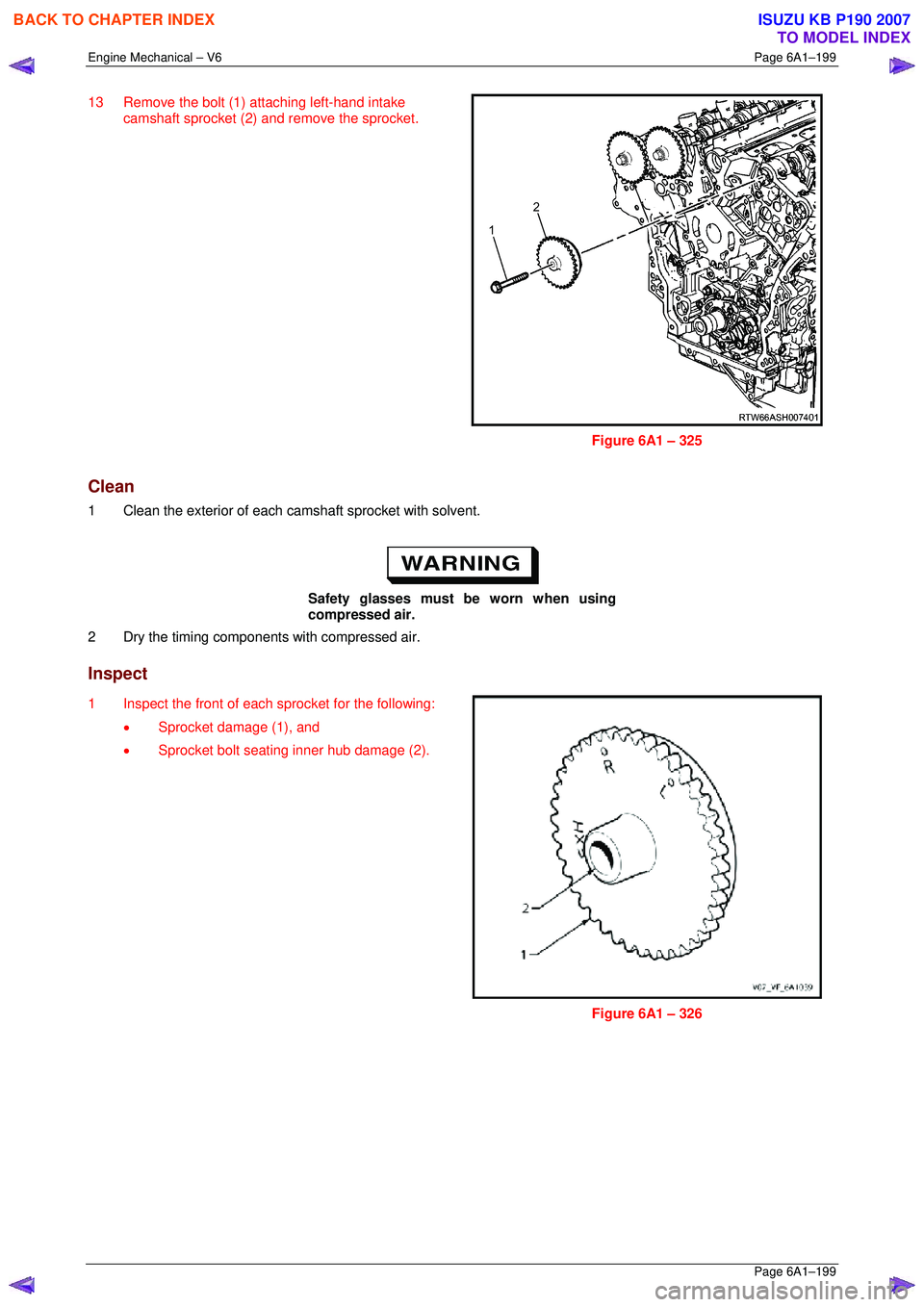
13 Remove the bolt (1) attaching left-hand intake
camshaft sprocket (2) and remove the sprocket.
Figure 6A1 – 325
Clean
1 Clean the exterior of each ca mshaft sprocket with solvent.
Safety glasses must be worn when using
compressed air.
2 Dry the timing components with compressed air.
Inspect
1 Inspect the front of each sprocket for the following:
• Sprocket damage (1), and
• Sprocket bolt seating inner hub damage (2).
Figure 6A1 – 326
BACK TO CHAPTER INDEX
TO MODEL INDEX
ISUZU KB P190 2007
Page 2977 of 6020
Engine Mechanical – V6 Page 6A1–200
Page 6A1–200
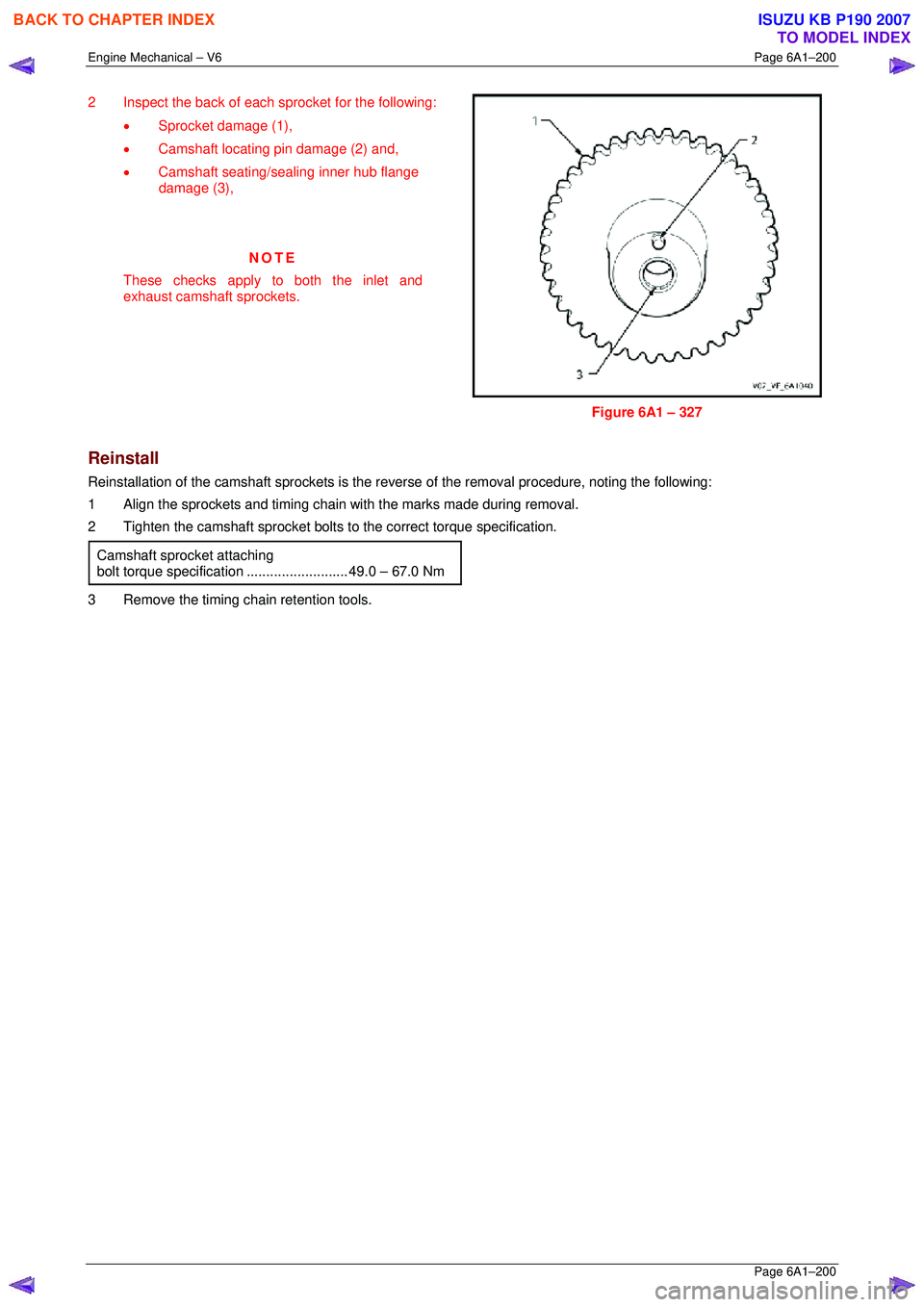
2 Inspect the back of each sprocket for the following:
• Sprocket damage (1),
• Camshaft locating pin damage (2) and,
• Camshaft seating/sealing inner hub flange
damage (3),
NOTE
These checks apply to both the inlet and
exhaust camshaft sprockets.
Figure 6A1 – 327
Reinstall
Reinstallation of the camshaft sprocke ts is the reverse of the removal procedure, noting the following:
1 Align the sprockets and timing chain with the marks made during removal.
2 Tighten the camshaft sprocket bolts to the correct torque specification.
Camshaft sprocket attaching
bolt torque specificat ion .......................... 49.0 – 67.0 Nm
3 Remove the timing chain retention tools.
BACK TO CHAPTER INDEX
TO MODEL INDEX
ISUZU KB P190 2007
Page 2978 of 6020
Engine Mechanical – V6 Page 6A1–201
Page 6A1–201
3.20 Camshaft
Remove
Right-hand Side
1 Remove the right-hand cylinder head camshaft sprockets, refer to 3.18 Camshaft Sprocket.
NOTE
Tool No. EN-46105–1 was installed as part of the
right-hand cylinder head camshaft sprocket
removal procedure.
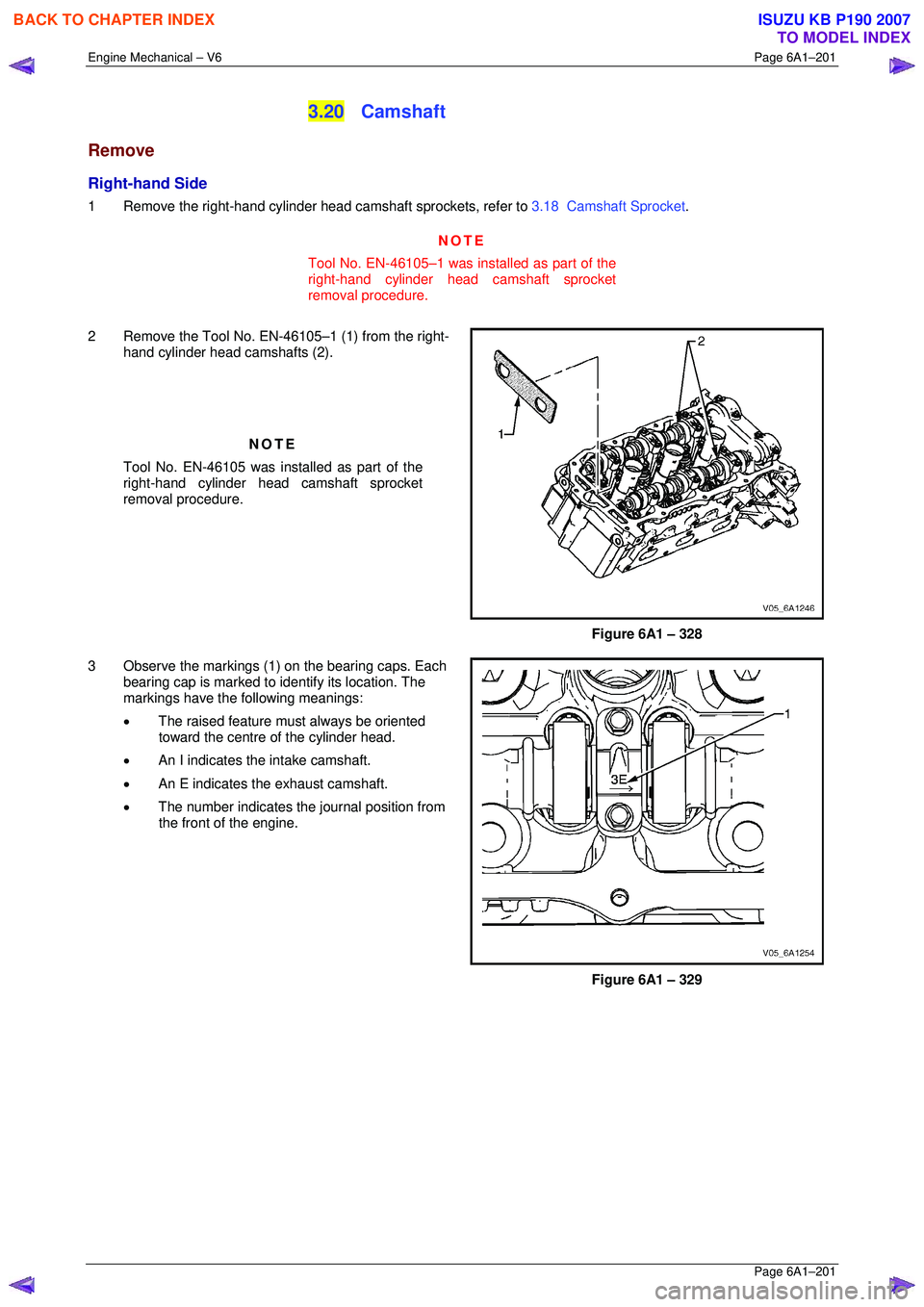
2 Remove the Tool No. EN-46105–1 (1) from the right- hand cylinder head camshafts (2).
NOTE
Tool No. EN-46105 was installed as part of the
right-hand cylinder head camshaft sprocket
removal procedure.
Figure 6A1 – 328
3 Observe the markings (1) on the bearing caps. Each bearing cap is marked to identify its location. The
markings have the following meanings:
• The raised feature must always be oriented
toward the centre of the cylinder head.
• An I indicates t he intake camshaft.
• An E indicates the exhaust camshaft.
• The number indicates the journal position from
the front of the engine.
Figure 6A1 – 329
BACK TO CHAPTER INDEX
TO MODEL INDEX
ISUZU KB P190 2007
Page 2979 of 6020
Engine Mechanical – V6 Page 6A1–202
Page 6A1–202
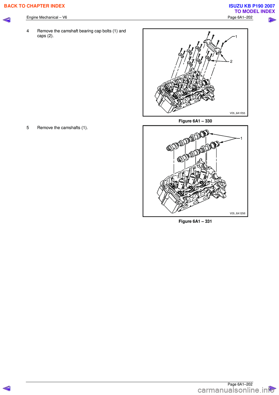
4 Remove the camshaft bearing cap bolts (1) and
caps (2).
Figure 6A1 – 330
5 Remove the camshafts (1).
Figure 6A1 – 331
BACK TO CHAPTER INDEX
TO MODEL INDEX
ISUZU KB P190 2007
Page 2980 of 6020
Engine Mechanical – V6 Page 6A1–203
Page 6A1–203
Left-hand Side
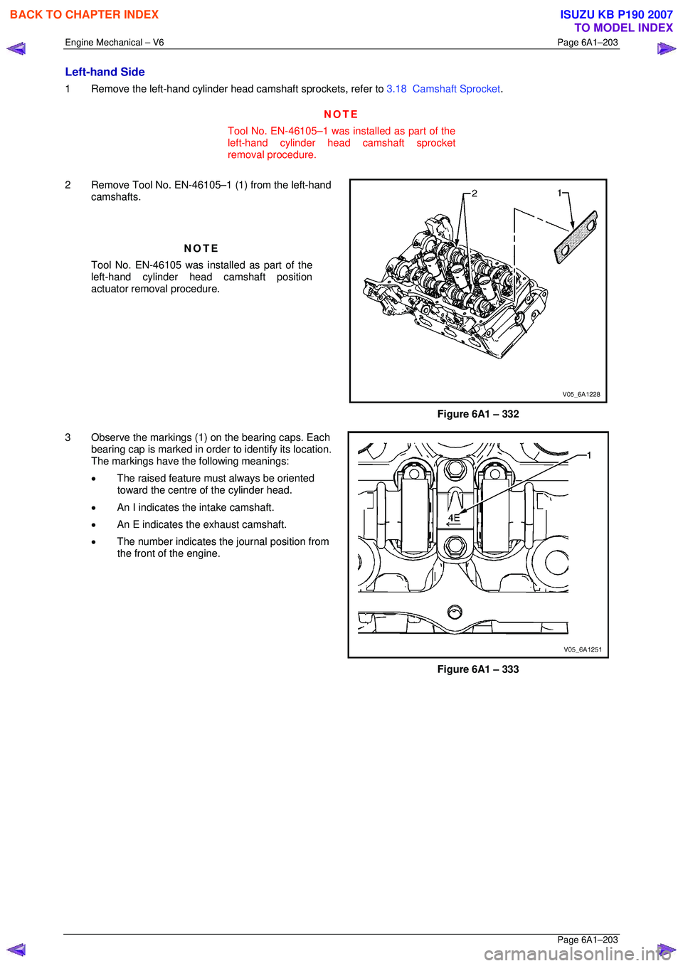
1 Remove the left-hand cylinder head camshaft sprockets, refer to 3.18 Camshaft Sprocket .
NOTE
Tool No. EN-46105–1 was installed as part of the
left-hand cylinder head camshaft sprocket
removal procedure.
2 Remove Tool No. EN-46105–1 (1) from the left-hand camshafts.
NOTE
Tool No. EN-46105 was installed as part of the
left-hand cylinder head camshaft position
actuator removal procedure.
Figure 6A1 – 332
3 Observe the markings (1) on the bearing caps. Each bearing cap is marked in order to identify its location.
The markings have the following meanings:
• The raised feature must always be oriented
toward the centre of the cylinder head.
• An I indicates t he intake camshaft.
• An E indicates the exhaust camshaft.
• The number indicates the journal position from
the front of the engine.
Figure 6A1 – 333
BACK TO CHAPTER INDEX
TO MODEL INDEX
ISUZU KB P190 2007