ISUZU KB P190 2007 Workshop Repair Manual
Manufacturer: ISUZU, Model Year: 2007, Model line: KB P190, Model: ISUZU KB P190 2007Pages: 6020, PDF Size: 70.23 MB
Page 2981 of 6020
Engine Mechanical – V6 Page 6A1–204
Page 6A1–204
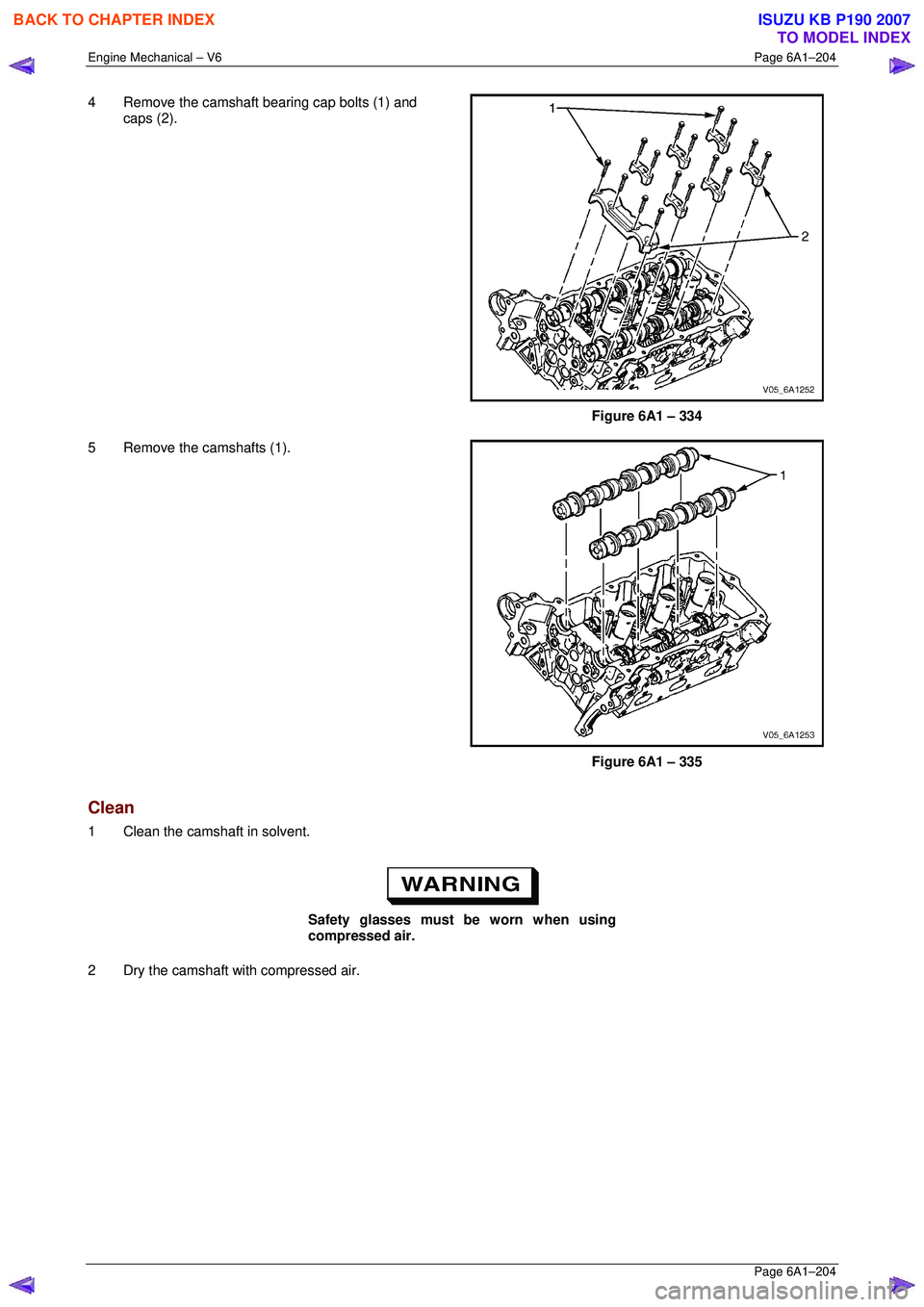
4 Remove the camshaft bearing cap bolts (1) and
caps (2).
Figure 6A1 – 334
5 Remove the camshafts (1).
Figure 6A1 – 335
Clean
1 Clean the camshaft in solvent.
Safety glasses must be worn when using
compressed air.
2 Dry the camshaft with compressed air.
BACK TO CHAPTER INDEX
TO MODEL INDEX
ISUZU KB P190 2007
Page 2982 of 6020
Engine Mechanical – V6 Page 6A1–205
Page 6A1–205
Inspect
Camshaft Visual Inspection
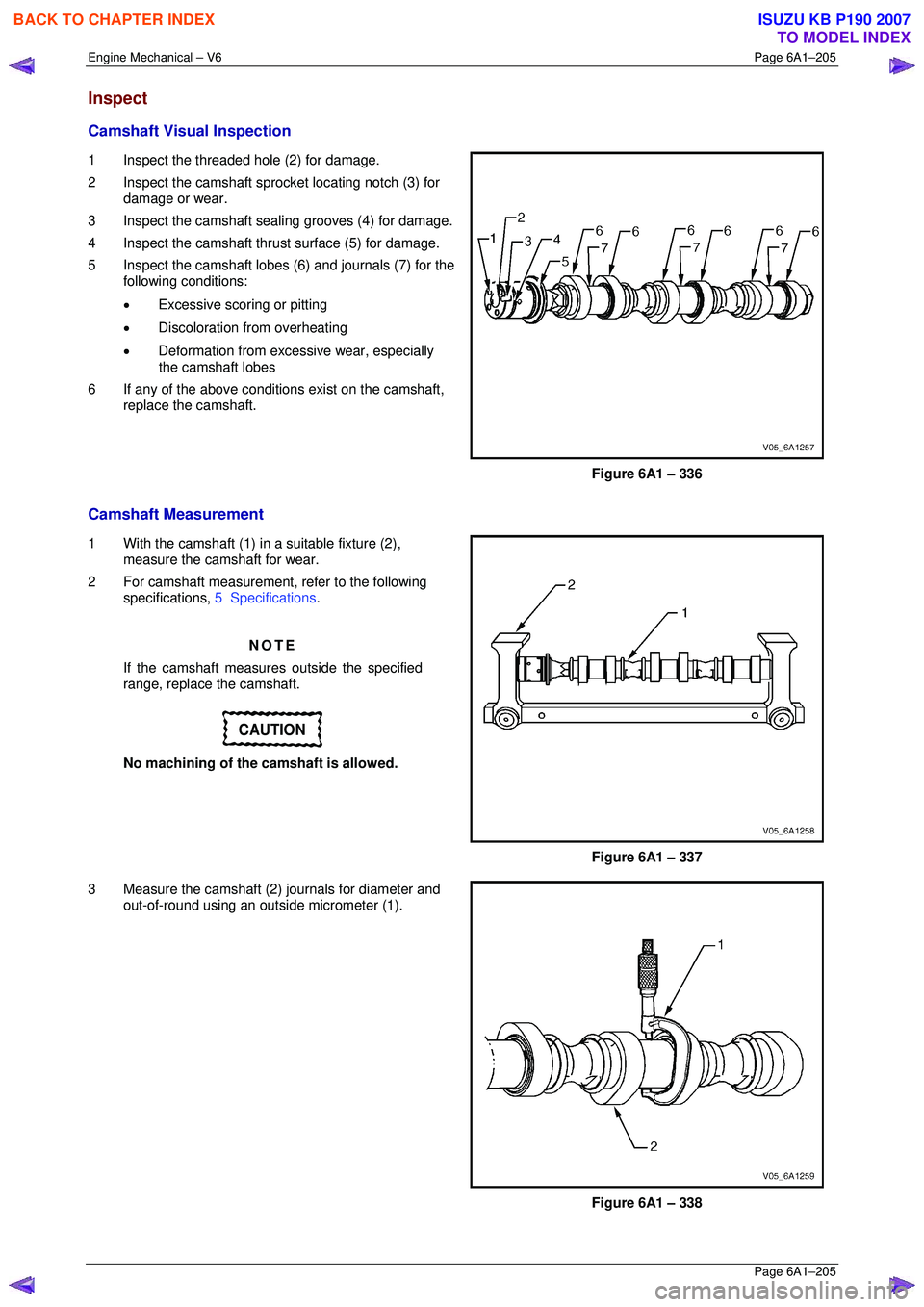
1 Inspect the threaded hole (2) for damage.
2 Inspect the camshaft spro cket locating notch (3) for
damage or wear.
3 Inspect the camshaft sealing grooves (4) for damage.
4 Inspect the camshaft thrust surface (5) for damage.
5 Inspect the camshaft lobes (6) and journals (7) for the following conditions:
• Excessive scoring or pitting
• Discoloration from overheating
• Deformation from excessive wear, especially
the camshaft lobes
6 If any of the above conditions exist on the camshaft, replace the camshaft.
Figure 6A1 – 336
Camshaft Measurement
1 With the camshaft (1) in a suitable fixture (2), measure the camshaft for wear.
2 For camshaft measurement, refer to the following specifications, 5 Specifications .
NOTE
If the camshaft measures outside the specified
range, replace the camshaft.
CAUTION
No machining of the camshaft is allowed.
Figure 6A1 – 337
3 Measure the camshaft (2) journals for diameter and out-of-round using an outsi de micrometer (1).
Figure 6A1 – 338
BACK TO CHAPTER INDEX
TO MODEL INDEX
ISUZU KB P190 2007
Page 2983 of 6020
Engine Mechanical – V6 Page 6A1–206
Page 6A1–206
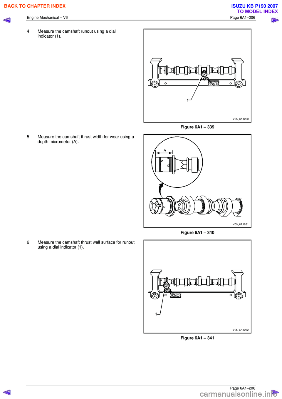
4 Measure the camshaft runout using a dial
indicator (1).
Figure 6A1 – 339
5 Measure the camshaft thrust width for wear using a depth micrometer (A).
Figure 6A1 – 340
6 Measure the camshaft thrust wall surface for runout using a dial indicator (1).
Figure 6A1 – 341
BACK TO CHAPTER INDEX
TO MODEL INDEX
ISUZU KB P190 2007
Page 2984 of 6020
Engine Mechanical – V6 Page 6A1–207
Page 6A1–207
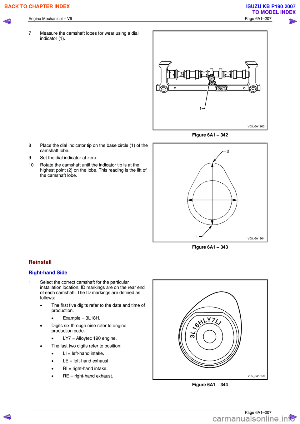
7 Measure the camshaft lobes for wear using a dial
indicator (1).
Figure 6A1 – 342
8 Place the dial indicator tip on the base circle (1) of the camshaft lobe.
9 Set the dial indicator at zero.
10 Rotate the camshaft until the indicator tip is at the highest point (2) on the lobe. This reading is the lift of
the camshaft lobe.
Figure 6A1 – 343
Reinstall
Right-hand Side
1 Select the correct camshaft for the particular installation location. ID markings are on the rear end
of each camshaft. The ID markings are defined as
follows:
• The first five digits refer to the date and time of
production.
• Example = 3L18H.
• Digits six through nine refer to engine
production code.
• LY7 = Alloytec 190 engine.
• The last two digits refer to position:
• LI = left-hand intake.
• LE = left-hand exhaust.
• RI = right-hand intake.
• RE = right-hand exhaust.
Figure 6A1 – 344
BACK TO CHAPTER INDEX
TO MODEL INDEX
ISUZU KB P190 2007
Page 2985 of 6020
Engine Mechanical – V6 Page 6A1–208
Page 6A1–208
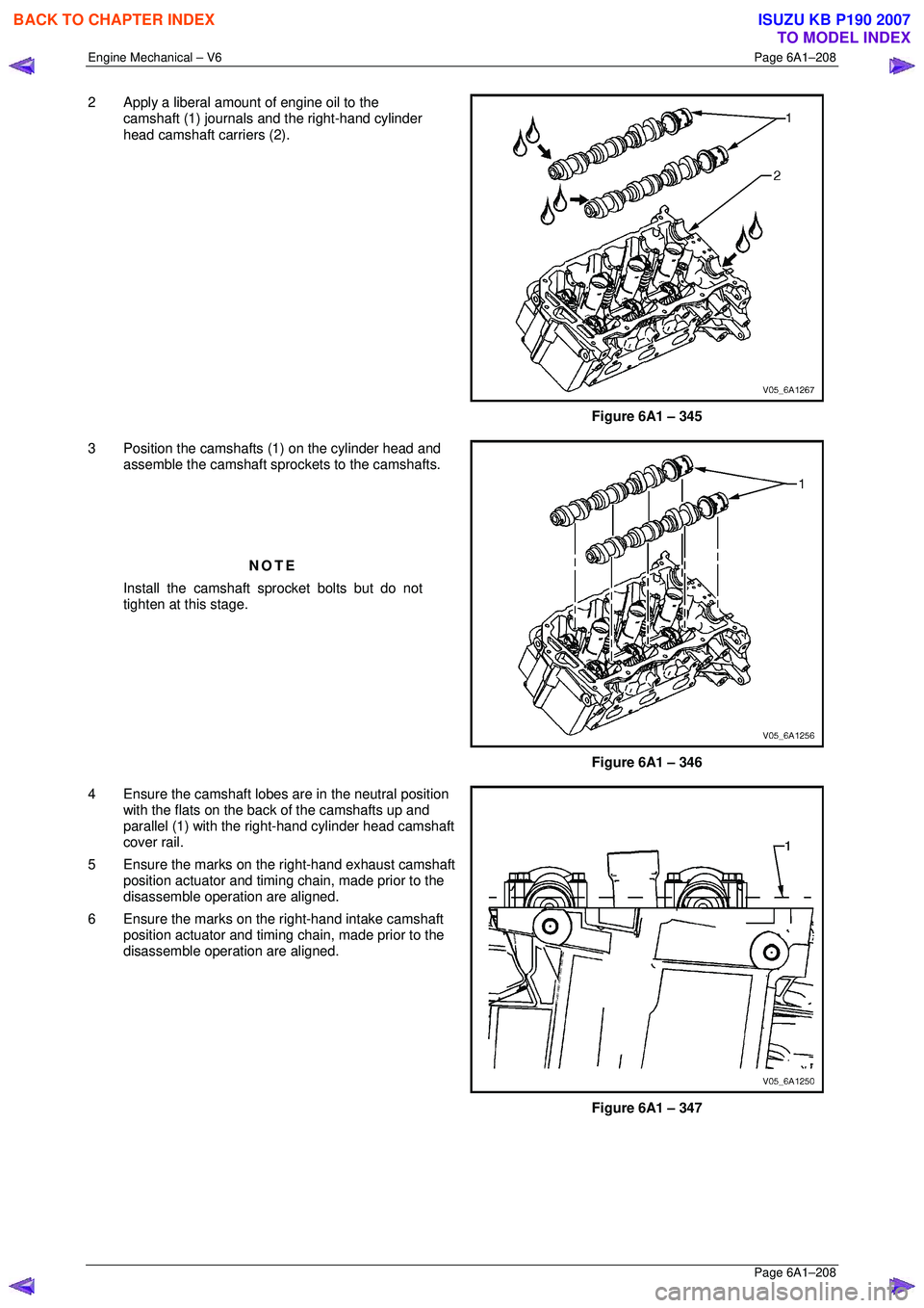
2 Apply a liberal amount of engine oil to the
camshaft (1) journals and the right-hand cylinder
head camshaft carriers (2).
Figure 6A1 – 345
3 Position the camshafts (1) on the cylinder head and assemble the camshaft spro ckets to the camshafts.
NOTE
Install the camshaft sprocket bolts but do not
tighten at this stage.
Figure 6A1 – 346
4 Ensure the camshaft lobes are in the neutral position with the flats on the back of the camshafts up and
parallel (1) with the right-hand cylinder head camshaft
cover rail.
5 Ensure the marks on the right-hand exhaust camshaft position actuator and timing chain, made prior to the
disassemble operation are aligned.
6 Ensure the marks on the right-hand intake camshaft position actuator and timing chain, made prior to the
disassemble operation are aligned.
Figure 6A1 – 347
BACK TO CHAPTER INDEX
TO MODEL INDEX
ISUZU KB P190 2007
Page 2986 of 6020
Engine Mechanical – V6 Page 6A1–209
Page 6A1–209
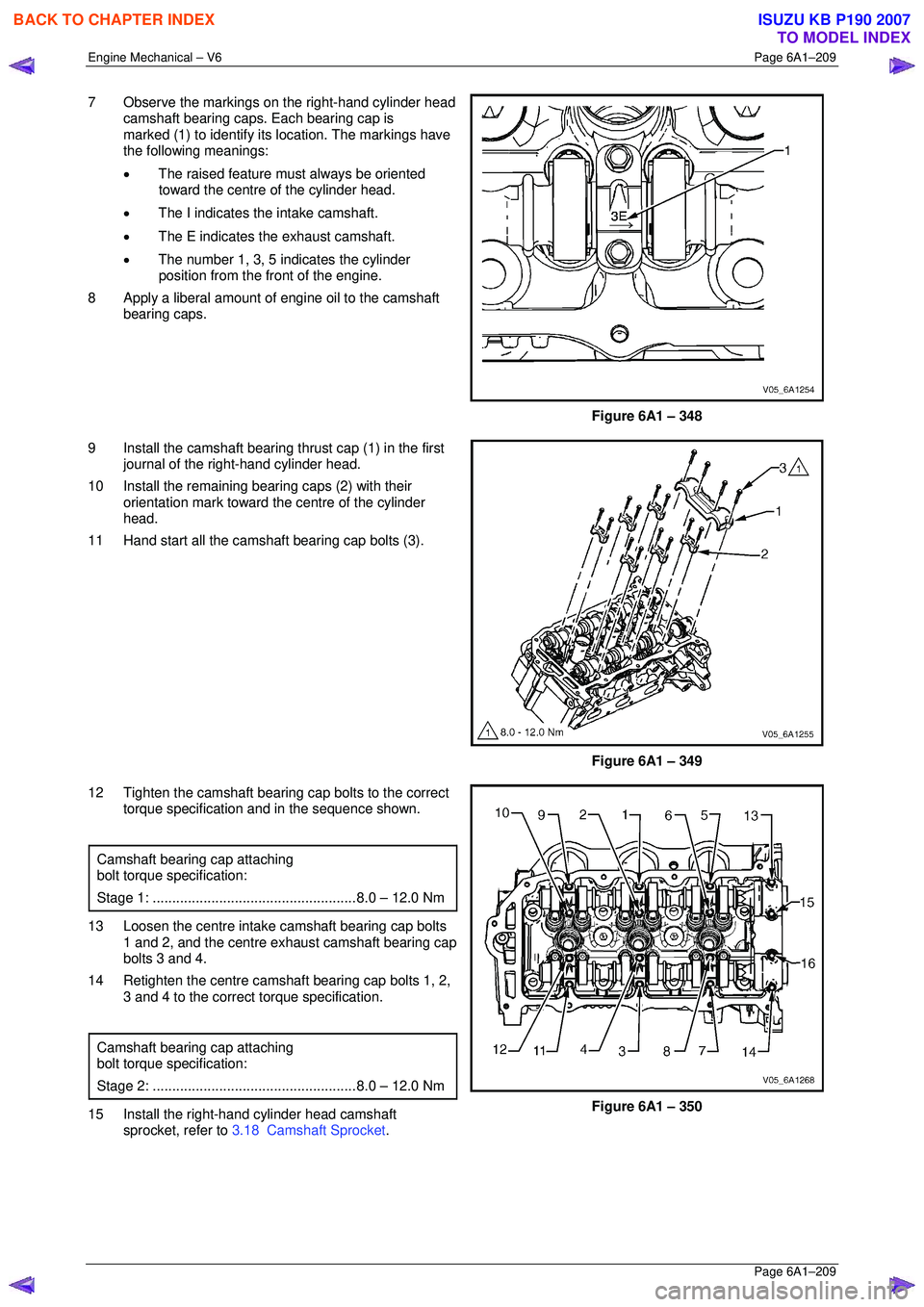
7 Observe the markings on the right-hand cylinder head
camshaft bearing caps. Each bearing cap is
marked (1) to identify its location. The markings have
the following meanings:
• The raised feature must always be oriented
toward the centre of the cylinder head.
• The I indicates the intake camshaft.
• The E indicates the exhaust camshaft.
• The number 1, 3, 5 indicates the cylinder
position from the fr ont of the engine.
8 Apply a liberal amount of engine oil to the camshaft bearing caps.
Figure 6A1 – 348
9 Install the camshaft bearing thrust cap (1) in the first journal of the right-hand cylinder head.
10 Install the remaining bearing caps (2) with their orientation mark toward t he centre of the cylinder
head.
11 Hand start all the camshaft bearing cap bolts (3).
Figure 6A1 – 349
12 Tighten the camshaft bearing cap bolts to the correct torque specification and in the sequence shown.
Camshaft bearing cap attaching
bolt torque specification:
Stage 1: .................................................... 8.0 – 12.0 Nm
13 Loosen the centre intake camshaft bearing cap bolts
1 and 2, and the centre exhaust camshaft bearing cap
bolts 3 and 4.
14 Retighten the centre camsha ft bearing cap bolts 1, 2,
3 and 4 to the correct torque specification.
Camshaft bearing cap attaching
bolt torque specification:
Stage 2: .................................................... 8.0 – 12.0 Nm
15 Install the right-hand cylinder head camshaft
sprocket, refer to 3.18 Camshaft Sprocket .
Figure 6A1 – 350
BACK TO CHAPTER INDEX
TO MODEL INDEX
ISUZU KB P190 2007
Page 2987 of 6020
Engine Mechanical – V6 Page 6A1–210
Page 6A1–210
Left-hand Side
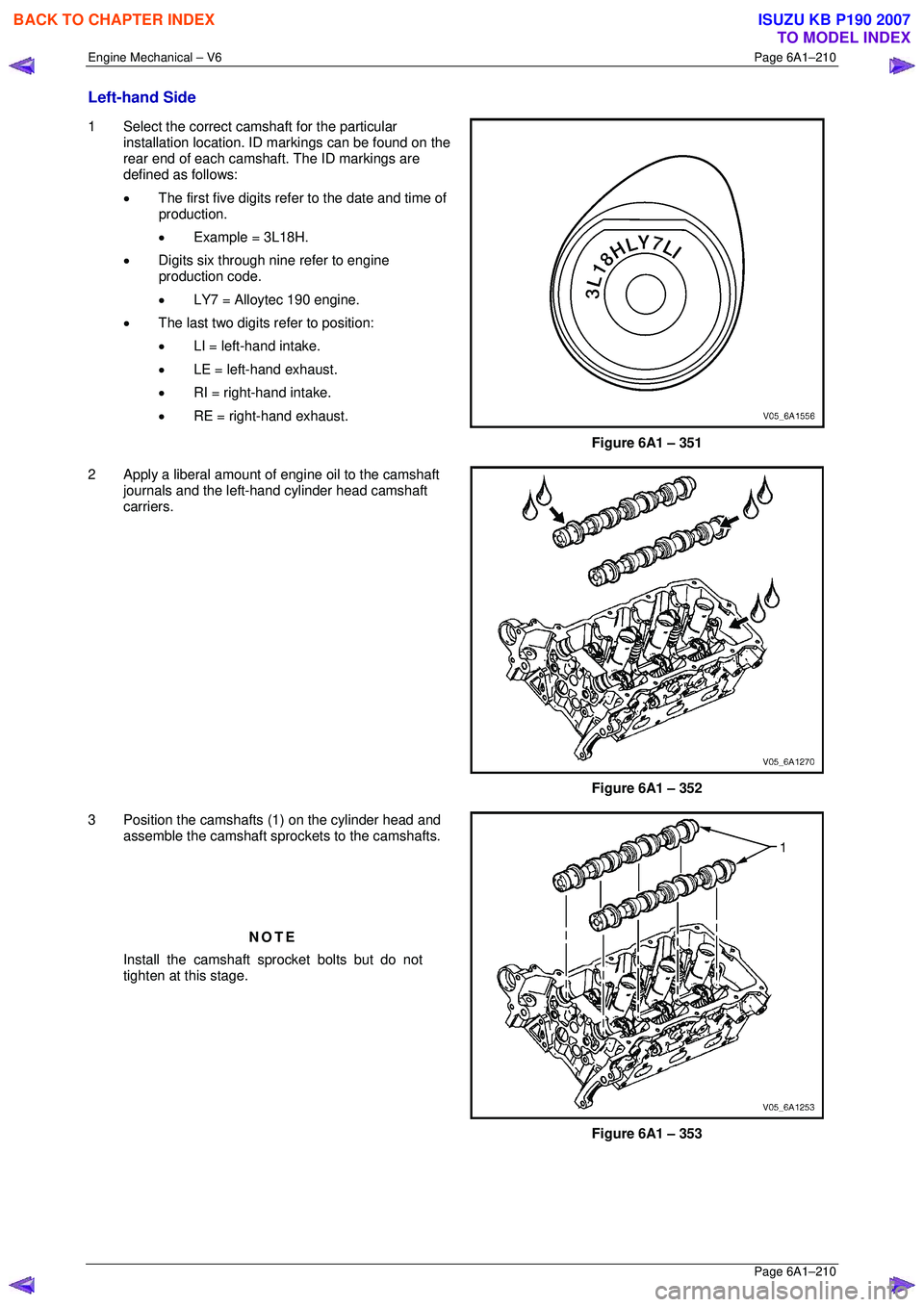
1 Select the correct camshaft for the particular
installation location. ID markings can be found on the
rear end of each camshaft. The ID markings are
defined as follows:
• The first five digits refer to the date and time of
production.
• Example = 3L18H.
• Digits six through nine refer to engine
production code.
• LY7 = Alloytec 190 engine.
• The last two digits refer to position:
• LI = left-hand intake.
• LE = left-hand exhaust.
• RI = right-hand intake.
• RE = right-hand exhaust.
Figure 6A1 – 351
2 Apply a liberal amount of engine oil to the camshaft journals and the left-hand cylinder head camshaft
carriers.
Figure 6A1 – 352
3 Position the camshafts (1) on the cylinder head and assemble the camshaft spro ckets to the camshafts.
NOTE
Install the camshaft sprocket bolts but do not
tighten at this stage.
Figure 6A1 – 353
BACK TO CHAPTER INDEX
TO MODEL INDEX
ISUZU KB P190 2007
Page 2988 of 6020
Engine Mechanical – V6 Page 6A1–211
Page 6A1–211
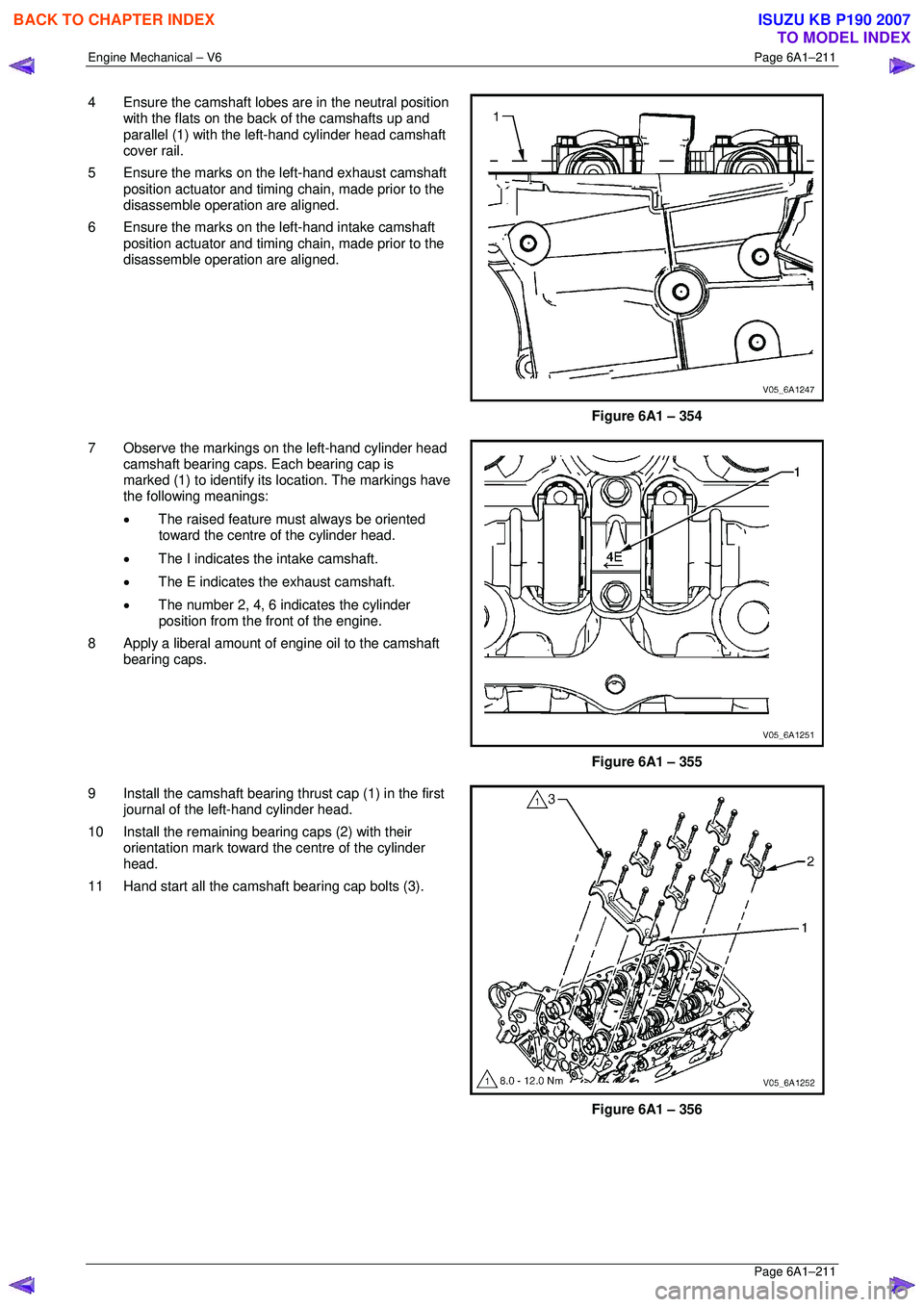
4 Ensure the camshaft lobes are in the neutral position
with the flats on the back of the camshafts up and
parallel (1) with the left-hand cylinder head camshaft
cover rail.
5 Ensure the marks on the left-hand exhaust camshaft position actuator and timing chain, made prior to the
disassemble operation are aligned.
6 Ensure the marks on the left-hand intake camshaft position actuator and timing chain, made prior to the
disassemble operation are aligned.
Figure 6A1 – 354
7 Observe the markings on the left-hand cylinder head camshaft bearing caps. Each bearing cap is
marked (1) to identify its location. The markings have
the following meanings:
• The raised feature must always be oriented
toward the centre of the cylinder head.
• The I indicates the intake camshaft.
• The E indicates the exhaust camshaft.
• The number 2, 4, 6 indicates the cylinder
position from the fr ont of the engine.
8 Apply a liberal amount of engine oil to the camshaft bearing caps.
Figure 6A1 – 355
9 Install the camshaft bearing thrust cap (1) in the first journal of the left-hand cylinder head.
10 Install the remaining bearing caps (2) with their orientation mark toward t he centre of the cylinder
head.
11 Hand start all the camshaft bearing cap bolts (3).
Figure 6A1 – 356
BACK TO CHAPTER INDEX
TO MODEL INDEX
ISUZU KB P190 2007
Page 2989 of 6020
Engine Mechanical – V6 Page 6A1–212
Page 6A1–212
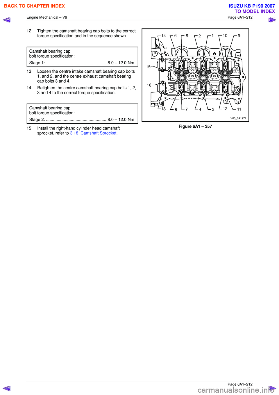
12 Tighten the camshaft bearing cap bolts to the correct
torque specification and in the sequence shown.
Camshaft bearing cap
bolt torque specification:
Stage 1: .................................................... 8.0 – 12.0 Nm
13 Loosen the centre intake camshaft bearing cap bolts
1, and 2, and the centre exhaust camshaft bearing
cap bolts 3 and 4.
14 Retighten the centre camsha ft bearing cap bolts 1, 2,
3 and 4 to the correct torque specification.
Camshaft bearing cap
bolt torque specification:
Stage 2: .................................................... 8.0 – 12.0 Nm
15 Install the right-hand cylinder head camshaft
sprocket, refer to 3.18 Camshaft Sprocket .
Figure 6A1 – 357
BACK TO CHAPTER INDEX
TO MODEL INDEX
ISUZU KB P190 2007
Page 2990 of 6020
Engine Mechanical – V6 Page 6A1–213
Page 6A1–213
3.21 Rocker Arm
Remove
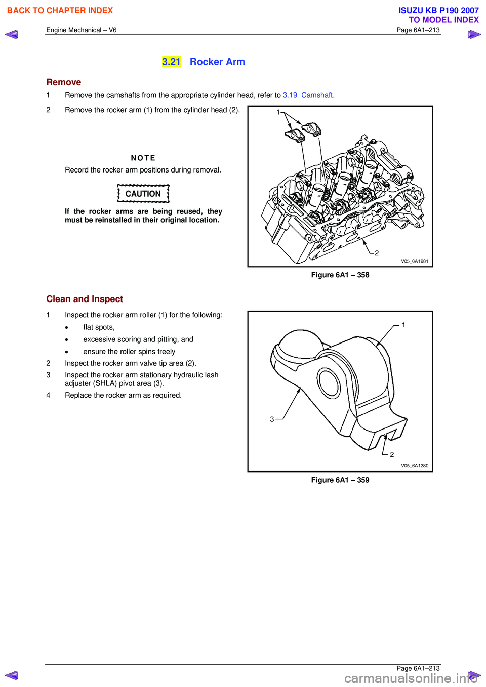
1 Remove the camshafts from the appropriate cylinder head, refer to 3.19 Camshaft.
2 Remove the rocker arm (1) from the cylinder head (2).
NOTE
Record the rocker arm positions during removal.
CAUTION
If the rocker arms are being reused, they
must be reinstalled in their original location.
Figure 6A1 – 358
Clean and Inspect
1 Inspect the rocker arm roller (1) for the following:
• flat spots,
• excessive scoring and pitting, and
• ensure the roller spins freely
2 Inspect the rocker arm valve tip area (2).
3 Inspect the rocker arm stationary hydraulic lash adjuster (SHLA) pivot area (3).
4 Replace the rocker arm as required.
Figure 6A1 – 359
BACK TO CHAPTER INDEX
TO MODEL INDEX
ISUZU KB P190 2007