maintenance ISUZU KB P190 2007 Workshop Owner's Manual
[x] Cancel search | Manufacturer: ISUZU, Model Year: 2007, Model line: KB P190, Model: ISUZU KB P190 2007Pages: 6020, PDF Size: 70.23 MB
Page 719 of 6020
5C-20 BRAKES
•
••
•
Operation
The operation of the P-valve by the master cylinde
r
pressure is unchanged up to the brake points
A and B.
If master cylinder fluid pressure penetrates into the second break point
B, the fluid pressure pressing against the seal
, (which isolated route 4 and route 5), passing the route
4of the master cylinder side, overcomes the operating
force of the spring
3 + fluid pressure affecting the seal 2of
the wheel cylinder, and presses the piston
1to the right
side, resulting in the opening of the routes
4 and 5, and
canceling of the P-valve operation.
Then, because the master cylinder fluid pressure and the wheel cylinder fluid pressure, up to the point
C, operate on
the identical surface of the seal
, both have identical
ascending ratios.
However, because of the operation of spring
3in the wheel
cylinder side, wheel cylinder fluid pressure operates to
preserve the balance against the master cylinder fluid
pressure on the lower level with the difference in pressure
resulting from this spring.
RTW 75CSH001601
Valve Maintenance
In the case of a fluid leak or other abnormality, the faulty valve
should be replaced.
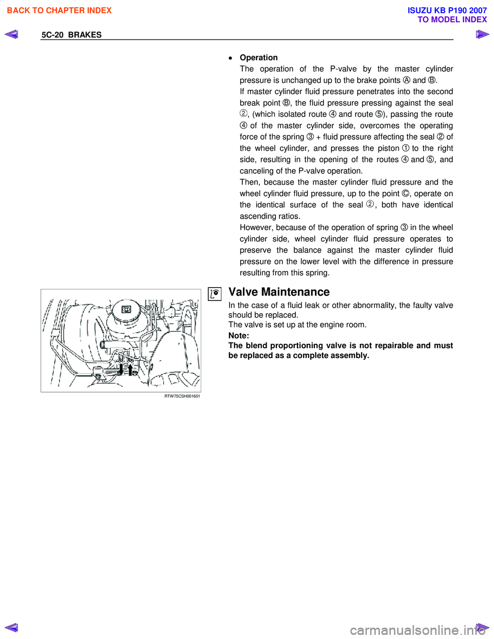
The valve is set up at the engine room.
Note:
The blend proportioning valve is not repairable and must
be replaced as a complete assembly.
BACK TO CHAPTER INDEX
TO MODEL INDEX
ISUZU KB P190 2007
Page 722 of 6020
BRAKES 5C-23
RTW 35CSH001301
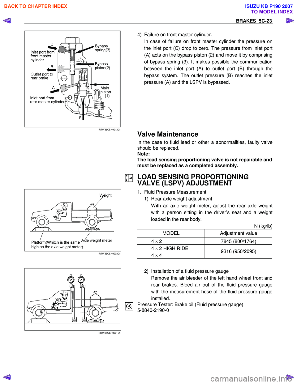
4) Failure on front master cylinder.
In case of failure on front master cylinder the pressure on the inlet port (C) drop to zero. The pressure from inlet port
(A) acts on the bypass piston (2) and move it by comprising
of bypass spring (3). It makes possible the communication
between the inlet port (A) to outlet port (B) through the
bypass system. The outlet pressure (B) reaches the inlet
pressure (A) and the LSPV is bypassed.
Valve Maintenance
In the case to fluid lead or other a abnormalities, faulty valve
should be replaced.
Note:
The load sensing proportioning valve is not repairable and
must be replaced as a completed assembly.
LOAD SENSING PROPORTIONING
VALVE (LSPV) ADJUSTMENT
RTW 35CSH000301
1. Fluid Pressure Measurement
1) Rear axle weight adjustment
W ith an axle weight meter, adjust the rear axle weight with a person sitting in the driver’s seat and a weight
loaded in the rear body. N (kg/lb)
MODEL Adjustment value
4 × 2 7845 (800/1764)
4 × 2 HIGH RIDE
4 × 4 9316 (950/2095)
RTW 35CSH000101
2) Installation of a fluid pressure gauge
Remove the air bleeder of the left hand wheel front and rear brakes. Bleed air out of the fluid pressure gauge
with the measurement hose of the fluid pressure gauge
installed.
Pressure Tester: Brake oil (Fluid pressure gauge)
5-8840-2190-0
BACK TO CHAPTER INDEX
TO MODEL INDEX
ISUZU KB P190 2007
Page 829 of 6020
6A – 24 ENGINE MECHANICAL
SERVICING
Servicing refers to general maintenance procedures to be performed by qualified service personnel.
RTW 36ASH000401
MODEL IDENTIFICATION
Engine Serial Number
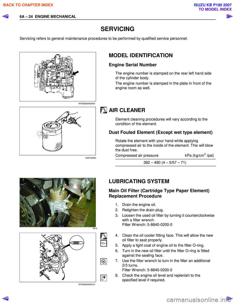
The engine number is stamped on the rear left hand side
of the cylinder body.
The engine number is stamped in the plate in front of the
engine room as well.
AIR CLEANER
Element cleaning procedures will vary according to the
condition of the element.
Dust Fouled Element (Except wet type element)
Rotate the element with your hand while applying
compressed air to the inside of the element. This will blow
the dust free.
Compressed air pressure kPa (kg/cm
2 /psi)
392 – 490 (4 – 5/57 – 71)
LUBRICATING SYSTEM
Main Oil Filter (Cartridge Type Paper Element)
Replacement Procedure
1. Drain the engine oil.
2. Retighten the drain plug.
3. Loosen the used oil filter by turning it counterclockwise with a filter wrench.
Filter W rench: 5-8840-0200-0
RTW 36ASH000101
4. Clean the oil cooler fitting face. This will allow the new oil filter to seat properly.
5. Apply a light coat of engine oil to the filter O-ring.
6. Turn in the new oil filter until the filter O-ring is fitted against the sealing face.
7. Use the filter wrench to turn in the filter an additional 2/3 turns.
Filter W rench: 5-8840-0200-0
8. Check the engine oil level and replenish to the specified level if required.
130RY00003
6A-6
BACK TO CHAPTER INDEX
TO MODEL INDEX
ISUZU KB P190 2007
Page 846 of 6020
ENGINE MECHANICAL 6A – 41
Coolant Replenishment
Warning:
When the coolant is heated to a high temperature, be
sure not to loosen or remove the rediator cap.
Otherwise you might get scalded by hot vapor or
boiling water.
To open the radiator cap, put a piece of thick cloth on
the cap and loosen the cap slowly to reduce the
pressure when the coolant has become cooler.
1. Open rediator cap pour coolant up to filler neck
2. Pour coolant into reservoir tank up to "MAX" line
3. Tighten radiator cap and start the engine. After idling for 2 to 3 minutes, stop the engine and reopen radiator
cap. If the water level is lower, replenish.
4. After replenish the coolant tighten radiator cap, warm up the engine at about 2000 rpm. Set heater
adjustment to the highest temperature position, and let
the coolant circulate also into heater water system.
5. Check to see the thermometer, continuously idling 5 minutes and stop the engine.
6. W hen the engine has been cooled, check filler neck for water level and replenish if required. Should extreme
shortage of coolant is found, check the coolant system
and reservoir tank hose for leakage.
7. Pour coolant into the reservoir tank up to "MAX" line.
Coolant Capacity lit (US/UK gal)
4JA1 / TC 9.4 (2.5 / 2.1)
4JH1TC M/T: 10.1 (2.7 / 2.2)
A/T: 10.0 (2.6 / 2.2)
Engine Warm-Up
After completing the required maintenance procedures,
start the engine and allow it to idle until it is warm.
Check the following:
1. Engine idling speed.
2. Engine noise level.
3. Engine lubricating system and cooling system. Carefully check for oil and coolant leakage.
4. Clutch engagement.
5. Transmission operation.
6. Indicator warning light operation.
BACK TO CHAPTER INDEX
TO MODEL INDEX
ISUZU KB P190 2007
Page 1033 of 6020
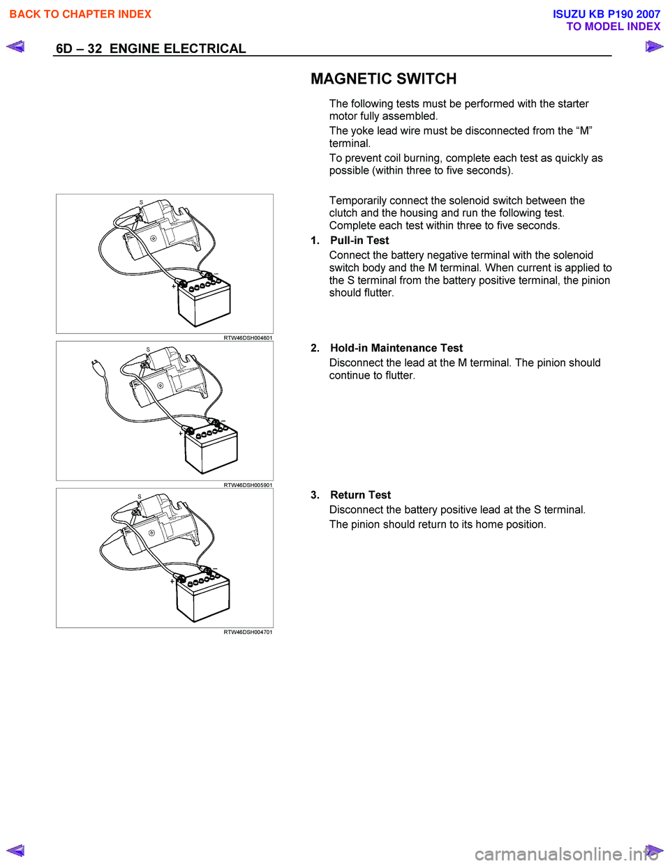
6D – 32 ENGINE ELECTRICAL
MAGNETIC SWITCH
The following tests must be performed with the starter
motor fully assembled.
The yoke lead wire must be disconnected from the “M ”
terminal.
To prevent coil burning, complete each test as quickly as
possible (within three to five seconds).
RTW46DSH004601
Temporarily connect the solenoid switch between the
clutch and the housing and run the following test.
Complete each test within three to five seconds.
1. Pull-in Test Connect the battery negative terminal with the solenoid
switch body and the M terminal. When current is applied to
the S terminal from the battery positive terminal, the pinion
should flutter.
RTW46DSH005901
2. Hold-in Maintenance Test
Disconnect the lead at the M terminal. The pinion should
continue to flutter.
RTW46DSH004701
3. Return Test
Disconnect the battery positive lead at the S terminal.
The pinion should return to its home position.
BACK TO CHAPTER INDEX
TO MODEL INDEX
ISUZU KB P190 2007
Page 1067 of 6020
Engine Control System (4JH1) 6E-33
Diagnostic System Check - Engine
Controls
Description
The Diagnostic System Check-Engine Controls is an
organized approach to identifying a condition that is
created by a malfunction in the electronic engine control
system. The Diagnostic System Check must be the
starting point for any driveability concern. The
Diagnostic System Check directs the service technician
to the next logical step in order to diagnose the concern.
Understanding and correctly using the diagnostic table
reduces diagnostic time, and prevents the replacement
of good parts.
Test Description
The numbers below refer to the step numbers on the
diagnostic table.
2. Lack of communication may be because of a partial
or a total malfunction of the Keyword 2000 serial data
circuit. The specified procedure determines the
particular condition.
11. If there are other modules with DTCs set, refer to
the DTC list. The DTC list directs you to the appropriate
diagnostic procedure. If the control module stores
multiple DTCs, diagnose the DTCs in the following
order.
• Component level DTCs, such as sensor DTCs,
solenoid DTCs, actuator DTCs, and relay DTCs.
Diagnose the multiple DTCs within this category in
numerical order. Begin with the lowest numbered
DTC, unless the diagnostic table directs you
otherwise.
Important:
• DO NOT perform this diagnostic if there is not a
driveability concern, unless another procedure
directs you to this diagnostic.
• Before you proceed with diagnosis, search fo
r
applicable service bulletins.
• Unless a diagnostic procedure instructs you, DO
NOT clear the DTCs.
• If there is a condition with the starting system, refe
r
to the starting system section in the engine
mechanical.
• Ensure the battery has a full charge.
• Ensure the battery cables (+) (-) are clean and
tight.
• Ensure the ECM grounds are clean, tight, and in
the correct location.
• Ensure the ECM harness connectors are clean and
correctly connected.
• Ensure the ECM terminals are clean and correctl
y
mating.
• Ensure the fuel injection pump control unit (PCU)
ground is clean, tight, and in the correct location.
• Ensure the PCU harness connectors are clean and
correctly connected.
• Ensure the PCU terminals are clean and correctl
y
mating.
• Ensure the vehicle maintenance has been done
enough.
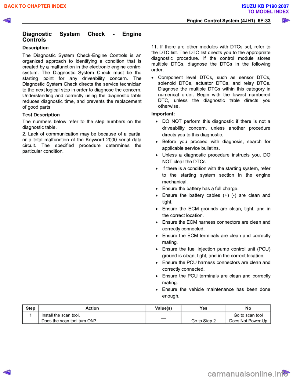
Step Action Value(s) Yes No
1 Install the scan tool.
Does the scan tool turn ON?
Go to Step 2 Go to scan tool
Does Not Power Up
BACK TO CHAPTER INDEX
TO MODEL INDEX
ISUZU KB P190 2007
Page 1082 of 6020
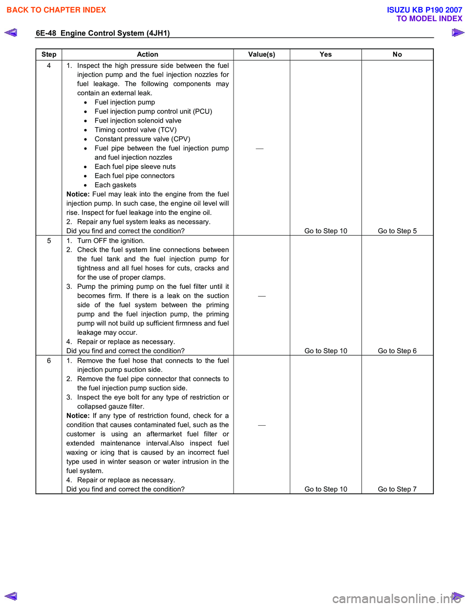
6E-48 Engine Control System (4JH1)
Step Action Value(s) Yes No
4 1. Inspect the high pressure side between the fuel
injection pump and the fuel injection nozzles for
fuel leakage. The following components may
contain an external leak. • Fuel injection pump
• Fuel injection pump control unit (PCU)
• Fuel injection solenoid valve
• Timing control valve (TCV)
• Constant pressure valve (CPV)
• Fuel pipe between the fuel injection pump
and fuel injection nozzles
• Each fuel pipe sleeve nuts
• Each fuel pipe connectors
• Each gaskets
Notice: Fuel may leak into the engine from the fuel
injection pump. In such case, the engine oil level will
rise. Inspect for fuel leakage into the engine oil.
2. Repair any fuel system leaks as necessary.
Did you find and correct the condition?
Go to Step 10 Go to Step 5
5 1. Turn OFF the ignition. 2. Check the fuel system line connections between the fuel tank and the fuel injection pump for
tightness and all fuel hoses for cuts, cracks and
for the use of proper clamps.
3. Pump the priming pump on the fuel filter until it becomes firm. If there is a leak on the suction
side of the fuel system between the priming
pump and the fuel injection pump, the priming
pump will not build up sufficient firmness and fuel
leakage may occur.
4. Repair or replace as necessary.
Did you find and correct the condition?
Go to Step 10 Go to Step 6
6 1. Remove the fuel hose that connects to the fuel injection pump suction side.
2. Remove the fuel pipe connector that connects to the fuel injection pump suction side.
3. Inspect the eye bolt for any type of restriction or collapsed gauze filter.
Notice: If any type of restriction found, check for a
condition that causes contaminated fuel, such as the
customer is using an aftermarket fuel filter or
extended maintenance interval.Also inspect fuel
waxing or icing that is caused by an incorrect fuel
type used in winter season or water intrusion in the
fuel system.
4. Repair or replace as necessary.
Did you find and correct the condition?
Go to Step 10 Go to Step 7
BACK TO CHAPTER INDEX
TO MODEL INDEX
ISUZU KB P190 2007
Page 1139 of 6020
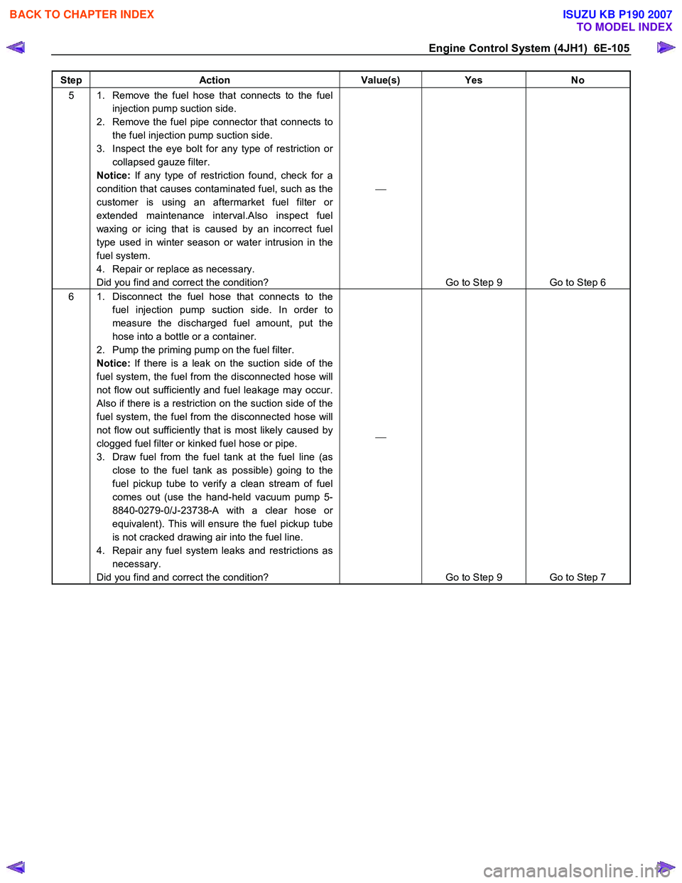
Engine Control System (4JH1) 6E-105
Step Action Value(s) Yes No
5 1. Remove the fuel hose that connects to the fuel
injection pump suction side.
2. Remove the fuel pipe connector that connects to the fuel injection pump suction side.
3. Inspect the eye bolt for any type of restriction or collapsed gauze filter.
Notice: If any type of restriction found, check for a
condition that causes contaminated fuel, such as the
customer is using an aftermarket fuel filter or
extended maintenance interval.Also inspect fuel
waxing or icing that is caused by an incorrect fuel
type used in winter season or water intrusion in the
fuel system.
4. Repair or replace as necessary.
Did you find and correct the condition?
Go to Step 9 Go to Step 6
6 1. Disconnect the fuel hose that connects to the fuel injection pump suction side. In order to
measure the discharged fuel amount, put the
hose into a bottle or a container.
2. Pump the priming pump on the fuel filter.
Notice: If there is a leak on the suction side of the
fuel system, the fuel from the disconnected hose will
not flow out sufficiently and fuel leakage may occur.
Also if there is a restriction on the suction side of the
fuel system, the fuel from the disconnected hose will
not flow out sufficiently that is most likely caused by
clogged fuel filter or kinked fuel hose or pipe.
3. Draw fuel from the fuel tank at the fuel line (as close to the fuel tank as possible) going to the
fuel pickup tube to verify a clean stream of fuel
comes out (use the hand-held vacuum pump 5-
8840-0279-0/J-23738-A with a clear hose or
equivalent). This will ensure the fuel pickup tube
is not cracked drawing air into the fuel line.
4. Repair any fuel system leaks and restrictions as necessary.
Did you find and correct the condition?
Go to Step 9 Go to Step 7
BACK TO CHAPTER INDEX
TO MODEL INDEX
ISUZU KB P190 2007
Page 1293 of 6020

Engine Control System (4JH1) 6E-259
Checks Action
Sensor Checks Inspect the engine control sensors for the following conditions. Refer to the scan tool
Data List in this section.
• Use the scan tool to compare the Engine Coolant Temperature (ECT) with the Intake
Air Temperature (IAT) and Fuel Temperature (FT) on a cold engine condition. If the
difference among temperature reading is more than 5°C (9°F) on a cold engine,
check for high resistance on the low reference circuit and signal circuit or for a
skewed sensor.
Notice: The mass air flow (MAF) sensor is heated and as a result the IAT sensor may
indicate a higher than normal intake air temperature if the ignition switch is being ON.
FT sensor is internal to the PCU and it is part of the fuel injection pump assembly.
• Inspect the crankshaft position (CKP) sensor is tight and the flywheel circumference
is not damaged.
Fuel System Checks Inspect the fuel system for the following conditions. Refer to the Fuel System section.
• Inspect for water contamination in the fuel.
• Inspect for external fuel leaks or fuel leakage into the engine oil.
• Inspect the fuel lines between the fuel tank and fuel injection pump for tightness and
all fuel hoses for cuts, cracks and for the use of proper clamps.
Notice: The fuel system from the fuel tank(s) to the fuel injection pump is under a
slight vacuum with the engine running. As a result, air can enter the fuel system if
these connections are not tight. Air in the fuel system will cause fuel injection pump
internal pressure fluctuations especially at high engine speed and load.
• Inspect for air in the fuel system.
Notice: If many air bubbles appear in the fuel, check the fuel system line connections
between the fuel tank and the fuel injection pump for tightness and all fuel hoses for
cuts, cracks and for the use of proper clamps.
a. Remove the fuel hose that connects to the fuel injection pump suction side.
b. Substitute a clear hose.
Notice: A hose must be cleaned.
c. Connect the clear hose to the fuel injection pump.
d. Bleed the fuel system.
e. Let the engine run at idle for at least 2 minutes.
f. Accelerator the engine between idle and W .O.T. (accelerator pedal full travel) many times while observing the clear hose.
• Inspect the fuel tank vent hose for a plugged or kinked.
• Inspect inside the fuel tank for any foreign material that may be getting drawn into
the fuel line pickup causing a blocked condition. Draw fuel from the fuel tank at the
fuel line (as close to the fuel tank as possible) going to the fuel pickup tube to verify a
clean stream of fuel comes out (use the hand-held vacuum pump 5-8840-0279-0/J-
23738-A with a clear hose or equivalent). This will ensure the fuel pickup tube is not
cracked drawing air into the fuel line.
• Inspect the fuel injection pump operation.
Notice: The fuel injection pump must be timed to the engine.
• Inspect the eye bolt for any type of restriction or collapsed gauze filter.
Notice: If any type of restriction found, check for a condition that causes contaminated
fuel, such as the customer is using an aftermarket fuel filter or extended maintenance
interval. Also inspect fuel waxing or icing that is caused by an incorrect fuel type used
in winter season or water intrusion in the fuel system.
• Inspect the fuel injection nozzle(s) for proper splay condition or operating pressure.
Notice: Only first stage of operating pressure can be checked.
Air Intake System Checks Inspect the air intake system for the following conditions.
• Inspect the air cleaner and air intake ducts for a restriction, holes, or leaks.
• Inspect for a restriction in the turbocharger inlet duct.
• Inspect for a restriction or deposit in the intake throttle bore.
• Inspect for a restriction or leak in the intake manifold.
Exhaust System Checks Inspect the exhaust system for a possible restriction. Refer to the Exhaust System
section.
• Inspect for a restriction in the catalytic converter or exhaust pipes.
BACK TO CHAPTER INDEX
TO MODEL INDEX
ISUZU KB P190 2007
Page 1295 of 6020
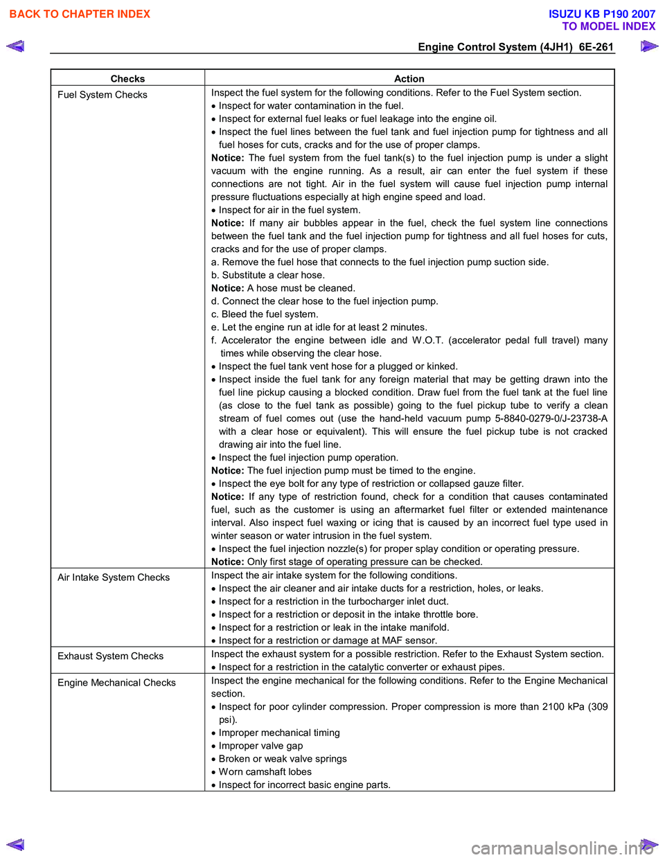
Engine Control System (4JH1) 6E-261
Checks Action
Fuel System Checks Inspect the fuel system for the following conditions. Refer to the Fuel System section.
• Inspect for water contamination in the fuel.
• Inspect for external fuel leaks or fuel leakage into the engine oil.
• Inspect the fuel lines between the fuel tank and fuel injection pump for tightness and all
fuel hoses for cuts, cracks and for the use of proper clamps.
Notice: The fuel system from the fuel tank(s) to the fuel injection pump is under a slight
vacuum with the engine running. As a result, air can enter the fuel system if these
connections are not tight. Air in the fuel system will cause fuel injection pump internal
pressure fluctuations especially at high engine speed and load.
• Inspect for air in the fuel system.
Notice: If many air bubbles appear in the fuel, check the fuel system line connections
between the fuel tank and the fuel injection pump for tightness and all fuel hoses for cuts,
cracks and for the use of proper clamps.
a. Remove the fuel hose that connects to the fuel injection pump suction side.
b. Substitute a clear hose.
Notice: A hose must be cleaned.
d. Connect the clear hose to the fuel injection pump.
c. Bleed the fuel system.
e. Let the engine run at idle for at least 2 minutes.
f. Accelerator the engine between idle and W .O.T. (accelerator pedal full travel) many times while observing the clear hose.
• Inspect the fuel tank vent hose for a plugged or kinked.
• Inspect inside the fuel tank for any foreign material that may be getting drawn into the
fuel line pickup causing a blocked condition. Draw fuel from the fuel tank at the fuel line
(as close to the fuel tank as possible) going to the fuel pickup tube to verify a clean
stream of fuel comes out (use the hand-held vacuum pump 5-8840-0279-0/J-23738-A
with a clear hose or equivalent). This will ensure the fuel pickup tube is not cracked
drawing air into the fuel line.
• Inspect the fuel injection pump operation.
Notice: The fuel injection pump must be timed to the engine.
• Inspect the eye bolt for any type of restriction or collapsed gauze filter.
Notice: If any type of restriction found, check for a condition that causes contaminated
fuel, such as the customer is using an aftermarket fuel filter or extended maintenance
interval. Also inspect fuel waxing or icing that is caused by an incorrect fuel type used in
winter season or water intrusion in the fuel system.
• Inspect the fuel injection nozzle(s) for proper splay condition or operating pressure.
Notice: Only first stage of operating pressure can be checked.
Air Intake System Checks Inspect the air intake system for the following conditions.
• Inspect the air cleaner and air intake ducts for a restriction, holes, or leaks.
• Inspect for a restriction in the turbocharger inlet duct.
• Inspect for a restriction or deposit in the intake throttle bore.
• Inspect for a restriction or leak in the intake manifold.
• Inspect for a restriction or damage at MAF sensor.
Exhaust System Checks Inspect the exhaust system for a possible restriction. Refer to the Exhaust System section.
• Inspect for a restriction in the catalytic converter or exhaust pipes.
Engine Mechanical Checks Inspect the engine mechanical for the following conditions. Refer to the Engine Mechanical
section.
• Inspect for poor cylinder compression. Proper compression is more than 2100 kPa (309
psi).
• Improper mechanical timing
• Improper valve gap
• Broken or weak valve springs
• W orn camshaft lobes
• Inspect for incorrect basic engine parts.
BACK TO CHAPTER INDEX
TO MODEL INDEX
ISUZU KB P190 2007