lock ISUZU KB P190 2007 Workshop Repair Manual
[x] Cancel search | Manufacturer: ISUZU, Model Year: 2007, Model line: KB P190, Model: ISUZU KB P190 2007Pages: 6020, PDF Size: 70.23 MB
Page 2162 of 6020

6D3-14 STARTING AND CHARGING SYSTEM
7. To remove the pulley, mount an 8mm Allen key in the vice
with the short end upwards, place a 24mm ring spanner on
the puley nut, position the internal hexagon of the roto
r
shaft onto the Allen ken, loosen the nut and remove the
pulley.
Note: the pulley has an integral boss which locks up against
the bearing,
therefore no thrust collar is provided.
8. Removing the rotor assembly. Remove the four retaining screws from the drive end housing, withdraw the roto
r
complete with the bearing.
Note: the rotor must not be pressed from the drive end housing
using a press as the bearing retaining plate and drive end
housing will be damaged or distorted. Parts removed in this
way must be replaced if the integrity of the generator is to be
maintained.
9. Remove the drive end bearing from the rotor shaft using a
chuck type puler, take care not to distort the fan assembl
y
during this process.
10. Remove the slipring end bearing using the same meghod as in 9.
Clean
Thoroughly clean all components except the rotor and stator
with an approved cleaning agent. Ensure that all traced of oil
and dirt are removed. If an abrasive cleaner is used to remove
scale and paint from the housings take care not to abrade the
bearing and mounting spigot surfaces. The rotor and stator
must be cleaned with compressed air only, the use of solvents
could cause damage to the insulating materials.
Inspection
1. Rectifier assembly
The following test equipment is required.
The recitifier assembly is not repairable and must be replaced
if a faulty diode is detected during inspection.
(a)
Adiode tester where the DC output at the test probes does
not exceed 14 volts or in the case of AC testers 12 volts
RMS. This is to ensue that when inspection rectifiers fitted
with zener power diodes the forward and reverse checks
are completer and are not masked by the diode turning on
due to the zener breakdown voltage.
(b) A zenere diode tester with a DC output in excess of 30 volts, the tester should also incorporate internal current
limiting set to 5 Ma. to prevent high currents during
inspection.
(c) Diodes can be destroyed during service due to high temperature and overload, open circuits are usually a result
of excessive voltage.
BACK TO CHAPTER INDEX
TO MODEL INDEX
ISUZU KB P190 2007
Page 2202 of 6020
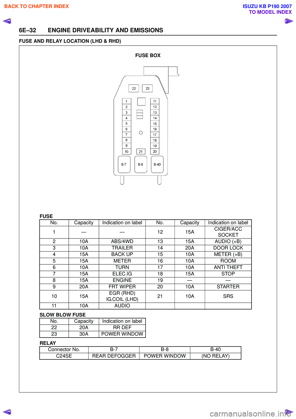
6E–32 ENGINE DRIVEABILITY AND EMISSIONS
FUSE AND RELAY LOCATION (LHD & RHD)
FUSE
SLOW BLOW FUSE
RELAY No. Capacity Indication on label No. Capacity Indication on label
1— — 1 215A CIGER/ACC
SOCKET
2 10A ABS/4WD 13 15A AUDIO (+B)
3 10A TRAILER 14 20A DOOR LOCK
4 15A BACK UP 15 10A METER (+B)
5 15A METER16 10A ROOM
6 10A TURN17 10A ANTI THEFT
7 15A ELEC.IG 18 15ASTOP
815A ENGINE 19 — —
9 20A FRT WIPER 20 10A STARTER
10 15A EGR (RHD)
IG.COIL (LHD) 21 10A
SRS
11 10A AUDIO
No. Capacity Indication on label 22 20A RR DEF
23 30A POWER WINDOW
Connector No. B-7B-8B-40
C24SE REAR DEFOGGER POWER WINDOW (NO RELAY)
FUSE BOX
BACK TO CHAPTER INDEX
TO MODEL INDEX
ISUZU KB P190 2007
Page 2220 of 6020
6E–50 ENGINE DRIVEABILITY AND EMISSIONS
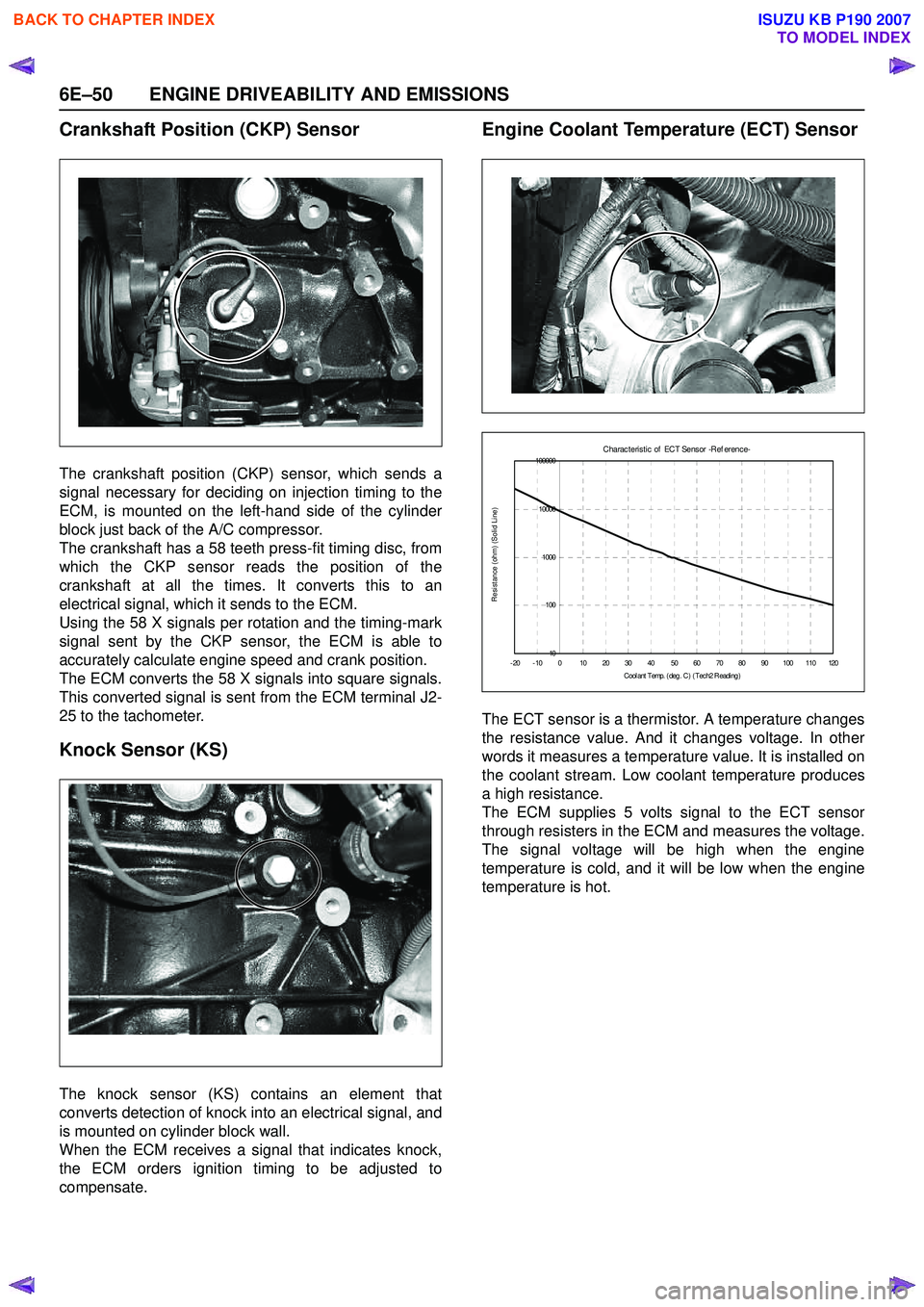
Crankshaft Position (CKP) Sensor
The crankshaft position (CKP) sensor, which sends a
signal necessary for deciding on injection timing to the
ECM, is mounted on the left-hand side of the cylinder
block just back of the A/C compressor.
The crankshaft has a 58 teeth press-fit timing disc, from
which the CKP sensor reads the position of the
crankshaft at all the times. It converts this to an
electrical signal, which it sends to the ECM.
Using the 58 X signals per rotation and the timing-mark
signal sent by the CKP sensor, the ECM is able to
accurately calculate engine speed and crank position.
The ECM converts the 58 X signals into square signals.
This converted signal is sent from the ECM terminal J2-
25 to the tachometer.
Knock Sensor (KS)
The knock sensor (KS) contains an element that
converts detection of knock into an electrical signal, and
is mounted on cylinder block wall.
When the ECM receives a signal that indicates knock,
the ECM orders ignition timing to be adjusted to
compensate.
Engine Coolant Temperature (ECT) Sensor
The ECT sensor is a thermistor. A temperature changes
the resistance value. And it changes voltage. In other
words it measures a temperature value. It is installed on
the coolant stream. Low coolant temperature produces
a high resistance.
The ECM supplies 5 volts signal to the ECT sensor
through resisters in the ECM and measures the voltage.
The signal voltage will be high when the engine
temperature is cold, and it will be low when the engine
temperature is hot.
C harac t eris t ic of ECT Sens or -R ef erenc e-
10
100
1000
10000
100000
-20-100 10203040 5060708090100110120 C ool ant T emp. ( deg . C ) ( Tec h2 R eadi ng )
Resistance (ohm) (Solid Line)
BACK TO CHAPTER INDEX
TO MODEL INDEX
ISUZU KB P190 2007
Page 2227 of 6020

ENGINE DRIVEABILITY AND EMISSIONS 6E–57
GENERAL DESCRIPTION FOR
EVAPORATIVE EMISSION SYSTEM
EVAP Emission Control System Purpose
The basic evaporative emission control system used on
the charcoal canister storage method. The method
transfers fuel vapor from the fuel tank to an activated
carbon (charcoal) storage devise to hold the vapors
when the vehicle is not operating.
The canister is located on the rear axle housing by the
frame cross-member.
When the engine is running, the fuel vapor is purged
from the carbon element by intake air flow and
consumed in the normal combustion process.
EVAP Emission Control System Operation
The EVAP canister purge is controlled by a solenoid
valve that allows the manifold vacuum to purge the
canister. The engine control module (ECM) supplies a
ground to energize the solenoid valve (purge on). The
EVAP purge solenoid control is pulse-width modulated
(PWM) (turned on and off several times a second). The
duty cycle (pulse width) is determined by engine
operating conditions including load, throttle position,
coolant temperature and ambient temperature. The duty
cycle is calculated by the ECM. the output is
commanded when the appropriate conditions have
been met. These conditions are:
• The engine is fully warmed up.
• The engine has been running for a specified time.
• The IAT reading is above 10°C (50°F).
• Purge/Vacuum Hoses. Made of rubber compounds, these hoses route the gasoline fumes from their
sources to the canister and from the canister to the
intake air flow.
• EVAP Canister. Mounted on a bracket ahead of the fuel tank, the canister stores fuel vapors until the
ECM determined that engine conditions are right for
them to be removed and burned.
Poor idle, stalling and Poor driveability can be caused
by:
• A malfunctioning purge solenoid.
• A damaged canister.
• Hoses that are split, cracked, or not connected properly.
System Fault Detection
The EVAP leak detection strategy is based on applying
vacuum to the EVAP system and monitoring vacuum
decay. At an appropriate time, the EVAP purge solenoid
is turned “ON,” allowing the engine vacuum to draw a
small vacuum on the entire evaporative emission
system.
After the desired vacuum level has been achieved, the
EVAP purge solenoid is turned “OFF,” sealing the
system. A leak is detected by monitoring for a decrease
in vacuum level over a given time period, all other
variables remaining constant.
If the desired vacuum level cannot be achieved in the
test described above, a large leak or a faulty EVAP
purge control solenoid valve is indicated.
Leaks can be caused by the following conditions:
• Missing or faulty fuel cap
• Disconnected, damaged, pinched, or blocked EVAP purge line
• Disconnected, damaged, pinched, or blocked fuel tank vapor line
• Disconnected or faulty EVAP purge control solenoid valve
• Open ignition feed circuit to the purge solenoid
(1) Purge Solenoid Valve
(2) From Canistor to Purge Solenoid
(3) From Purge Solenoid to Intake
(1) Canistor
(2) Air Separator
132
12
BACK TO CHAPTER INDEX
TO MODEL INDEX
ISUZU KB P190 2007
Page 2233 of 6020
ENGINE DRIVEABILITY AND EMISSIONS 6E–63
3. Check Bulletins and Troubleshooting Hints
NOTE: As estimated 30 percent of successful vehicle
repairs are diagnosed with this step!
What you should do
You should have enough information gained from
preliminary checks to accurately search for a bulletin
and other related service information. Some service
manual sections provide troubleshooting hints that
match symptoms with specific complaints.
What resources you should use
You should use the following resources for assistance in
checking for bulletins and troubleshooting hints:
• Printed bulletins
• Access ISUZU Bulletin Web site.
• Videotapes
• Service manual
4. Perform Service Manual Diagnostic Checks
What you should do
The “System Checks” in most service manual sections
and in most cells of section 8A (electrical) provide you
with:
• A systematic approach to narrowing down the possible causes of a system fault
• Direction to specific diagnostic procedures in the service manual
• Assistance to identify what systems work correctly
What resources you should use
Whenever possible, you should use the following
resources to perform service manual checks:
• Service manual
• Technical equipment (for viewing DTCs and analyzing data)
• Digital multimeter and circuit testing tools
• Other tools as needed
5a and 5b. Perform Service Manual Diagnostic Procedures
NOTE: An estimated 40 percent of successful vehicle
repairs are diagnosed with these steps!
What you should do
When directed by service manual diagnostic checks,
you must then carefully and accurately perform the
steps of diagnostic procedures to locate the fault related to the customer complaint.
What resources you should use
Whenever appropriate, you should use the following
resources to perform service manual diagnostic
procedures:
• Service manual
• Technical equipment (for analyzing diagnostic data)
• Digital multimeter and circuit testing tools
• Essential and special tools
5c. Technician Self Diagnoses
When there is no DTC stored and no matching
symptom for the condition identified in the service
manual, you must begin with a thorough understanding
of how the system(s) operates. Efficient use of the
service manual combined with you experience and a
good process of elimination will result in accurate
diagnosis of the condition.
What you should do
Step 1: Identify and understand the suspect
circuit(s)
Having completed steps 1 through 4 of the Strategy
Based Diagnostics chart, you should have enough
information to identify the system(s) or sub-system(s)
involved. Using the service manual, you should
determine and investigate the following circuit
characteristics:
• Electrical: – How is the circuit powered (power distributioncharts and/or fuse block details)?
– How is the circuit grounded (ground distribution charts)?
– How is the circuit controlled or sensed (theory of operation):
– If it is a switched circuit, is it normally open or normally closed?
– Is the power switched or is the ground switched?
– Is it a variable resistance circuit (ECT sensor or TP sensor, for example)?
– Is it a signal generating device (MAF sensor of VSS, for example)?
– Does it rely on some mechanical/vacuum device to operate?
•Physical:
– Where are the circuit components (componentlocators and wire harness routing diagrams):
– Are there areas where wires could be chafed or pinched (brackets or frames)?
– Are there areas subjected to extreme temperatures?
BACK TO CHAPTER INDEX
TO MODEL INDEX
ISUZU KB P190 2007
Page 2260 of 6020

6E–90 ENGINE DRIVEABILITY AND EMISSIONS
ON-BOARD DIAGNOSTIC (OBD) SYSTEM CHECK
Circuit Description
The on-board diagnostic system check is the starting
point for any driveability complaint diagnosis. Before
using this procedure, perform a careful visual/physical
check of the ECM and engine grounds for cleanliness
and tightness.
The on-board diagnostic system check is an organized
approach to identifying a problem created by an
electronic engine control system malfunction.
Diagnostic Aids
An intermittent may be caused by a poor connection,
rubbed-through wire insulation or a wire broken inside
the insulation. Check for poor connections or a
damaged harness. Inspect the ECM harness and
connector for improper mating, broken locks, improperly
formed or damaged terminals, poor terminal-to-wire
connection, and damaged harness.
Te s t D e s c r i p t i o n
Number(s) below refer the step number(s) on the
Diagnostic Chart:
1. The Check Engine Lamp (MIL) should be ON steady
with the ignition “On”, engine “Off”. If not, “No Check
Engine Lamp (MIL)” chart should be used to isolate the
malfunction.
2. Checks the Class 2 data circuit and ensures that the
ECM is able to transmit serial data.
3. This test ensures that the ECM is capable of
controlling the Check Engine Lamp (MIL) and the Check
Engine Lamp (MIL) driver circuit is not shorted to
ground circuit.
4. If the engine will not start, “Engine Cranks But Will
Not Run” chart should be used to diagnose the fault.
6. The Tech2 parameters which is not within the typical
range may help to isolate the area which is causing the
problem.
12. This vehicle is equipped with ECM which utilizes an
electrically erasable programmable read only memory
(EEPROM).
BACK TO CHAPTER INDEX
TO MODEL INDEX
ISUZU KB P190 2007
Page 2264 of 6020
6E–94 ENGINE DRIVEABILITY AND EMISSIONS
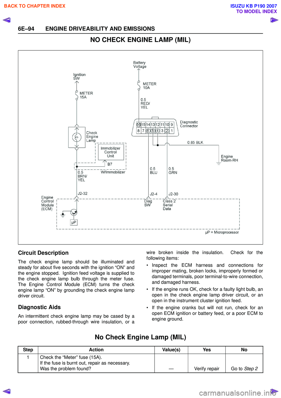
NO CHECK ENGINE LAMP (MIL)
Circuit Description
The check engine lamp should be illuminated and
steady for about five seconds with the ignition “ON” and
the engine stopped. Ignition feed voltage is supplied to
the check engine lamp bulb through the meter fuse.
The Engine Control Module (ECM) turns the check
engine lamp “ON” by grounding the check engine lamp
driver circuit.
Diagnostic Aids
An intermittent check engine lamp may be cased by a
poor connection, rubbed-through wire insulation, or a wire broken inside the insulation. Check for the
following items:
• Inspect the ECM harness and connections for improper mating, broken locks, improperly formed or
damaged terminals, poor terminal-to-wire connection,
and damaged harness.
• If the engine runs OK, check for a faulty light bulb, an open in the check engine lamp driver circuit, or an
open in the instrument cluster ignition feed.
• If the engine cranks but will not run, check for an open ECM ignition or battery feed, or a poor ECM to
engine ground.
No Check Engine Lamp (MIL)
Step Action Value(s) Yes No
1 Check the “Meter” fuse (15A). If the fuse is burnt out, repair as necessary.
Was the problem found? — Verify repair Go to Step 2
BACK TO CHAPTER INDEX
TO MODEL INDEX
ISUZU KB P190 2007
Page 2266 of 6020

6E–96 ENGINE DRIVEABILITY AND EMISSIONS
CHECK ENGINE LAMP (MIL) “ON” STEADY
Circuit description
The check engine lamp should always be illuminated
and steady for about five seconds with ignition “ON” and
the engine stopped. Ignition feed voltage is supplied
directly to the check engine lamp indicator. The Engine
Control Module (ECM) turns the check engine lamp
“ON” by grounding the check engine lamp driver circuit.
The check engine lamp should not remain “ON” with the
engine running and no DTC(s) set. A steady check
engine lamp with the engine running and no DTC(s)
suggests a short to ground in the check engine lamp
driver circuit.
Diagnostic Aids
An intermittent may be caused by a poor connection,
rubbed-through wire insulation, or a wire broken inside
the insulation. Check for the following items:
• Poor connection or damaged harness - Inspect the ECM harness and connectors for improper mating,
broken locks, improperly formed or damaged
terminals, poor terminal-to-wire connection, and
damaged harness.
Check Engine Lamp (MIL) “ON” Steady
Step Action Value(s) Yes No
1 1. Ignition “Off”, engine “Off”. 2. Disconnect the ECM connector.
3. Ignition “On”.
Was the “CHECK ENGINE” lamp turned on? — Go to Step 2Go to Step 4
BACK TO CHAPTER INDEX
TO MODEL INDEX
ISUZU KB P190 2007
Page 2273 of 6020

ENGINE DRIVEABILITY AND EMISSIONS 6E–103
FUEL SYSTEM ELECTRICAL TEST
Circuit Description
When the ignition switch is first turned ON, the engine
control module (ECM) energizes the fuel pump relay
which applies power to the in-tank fuel pump. The fuel
pump relay will remain ON as long as the engine is
running or cranking and the ECM is receiving 58X
crankshaft position pulses. If no 58X crankshaft position
pulses are present, the ECM de-energizes the fuel
pump relay within 2 seconds after the ignition is turned
ON or the engine is stopped.
The fuel pump delivers fuel to the fuel rail and injectors,
then to the fuel pressure regulator. The fuel pressure
regulator controls fuel pressure by allowing excess fuel
to be returned to the fuel tank. With the engine stopped
and ignition ON, the fuel pump can be turned ON by
using a command by the scan tool.
Diagnostic Aids
An intermittent may be caused by a poor connection,
rubbed-through wire insulation, or a wire broken inside
the insulation. Check for the following items:
• Poor connection or damaged harness - Inspect the ECM harness and connectors for improper mating,
broken locks, improperly formed or damaged
terminals, poor terminal-to-wire connection, and
damaged harness. Caution: To reduce the risk of fire and personal
injury:
• It is necessary to relieve fuel system pressure before connecting a fuel pressure gauge.
Refer to Fuel Pressure Relief Procedure,
below.
• A small amount of fuel may be released when disconnecting the fuel lines. Cover fuel line
fittings with a shop towel before
disconnecting, to catch any fuel that may leak
out. Place the towel in an approved container
when the disconnect is completed.
BACK TO CHAPTER INDEX
TO MODEL INDEX
ISUZU KB P190 2007
Page 2281 of 6020
ENGINE DRIVEABILITY AND EMISSIONS 6E–111
10 Locate and repair the loss of vacuum to the fuelpressure regulator.
Is the action complete? — Verify repair —
11 Replace the fuel pressure regulator. Is the action complete? — Verify repair —
12 1. Run the fuel pump with the Scan Tool. 2. After pressure has built up, turn off the pump andclamp the supply hose shut with suitable locking
pliers.
Does the fuel pressure indicated by the fuel pressure
gauge remain constant? — Go to Step 13Go to Step 15
13 Visually inspect the fuel supply line and repair any leaks.
Was a problem found? — Verify repair Go to Step 14
14 Remove the fuel tank and inspect for leaky hose or in- tank fuel line.
Was a problem found? — Verify repair Go to Step 8
15 1. If the pliers are still clamped to the fuel supply hose, remove the locking pliers.
2. With suitable locking pliers, clamp the fuel return line to prevent fuel from returning to the fuel tank.
3. Run the fuel pump with the Scan Tool.
4. After pressure has built up, remove power to the pump.
Does the fuel pressure indicated by the fuel pressure
gauge remain constant? — Go to Step 11Go to Step 16
16 Locate and replace any leaking fuel injector(s). Is the action complete? — Verify repair —
17 Is the fuel pressure indicated by the fuel pressure gauge above the specified limit? 376 kPa
(55 psi) Go to Step 18Go to Step 21
18 1. Relieve the fuel pressure. Refer to the Fuel
Pressure Relief .
2. Disconnect the fuel return line from the fuel rail.
3. Attach a length of flexible hose to the fuel rail return outlet passage.
4. Place the open end of the flexible hose into an approved gasoline container.
5. Run the fuel pump with the Scan Tool.
6. Observe the fuel pressure indicated by the fuel pressure gauge with the fuel pump running.
Is the fuel pressure within the specified limits? 290-376 kPa
(42-55 psi) Go to Step 19Go to Step 20
19 Locate and correct the restriction in the fuel return line.
Is the action complete? — Verify repair —
20 Visually and physically inspect the fuel rail outlet passages for a restriction.
Was a restriction found? — Verify repair Go to Step 11
21 Is the fuel pressure indicated by the fuel pressure gauge above the specified value? 0 kPa (0 psi) Go to Step 22Go to Step 23
Step
Action Value(s) Yes No
BACK TO CHAPTER INDEX
TO MODEL INDEX
ISUZU KB P190 2007