relay ISUZU KB P190 2007 Workshop Repair Manual
[x] Cancel search | Manufacturer: ISUZU, Model Year: 2007, Model line: KB P190, Model: ISUZU KB P190 2007Pages: 6020, PDF Size: 70.23 MB
Page 5903 of 6020

IMMOBILIZER SYSTEM (C24SE, 4JA1-T) 11A-5
What happens without proper transponder
operation?
One of the function of transponder is to deactivate or
activate starter function. lf the proper transponder is not
used, starter cannot be operated. Because starter rela
y
stays off, cranking engine is not possible.
After the starter relay is activated, transponder signal
triggers to let lCU calculate by transponder address
signal and immobilizer algorithm.
W hen the result matches with necessary condition, it
makes injector power source be activated.
If transponder does not send correct signal, lCU and
ECM do not activate injector system on.
Therefore the vehicle cannot be operated.
No proper transponder is available, what
should be done for the system?
W hen any proper transponder is not available, a new
transponder should be programmed. Up to 5
transponders can be provided with a scan tool (Tech-2)
and by proper procedure.
In addition to the absence of proper transponder, it ma
y
happen particular secret code to the particular vehicle is
missing. ln this case, the secret code must be provided
by your organization.
Otherwise transponder cannot be programmed in an
y
way.
lf the essential for a scan tool (Tech-2) for programming
and proper software for Tech-2 are not available, there
is no permanent way to fix system. Temporary replace
with new ECM, new ICU and new transponder without
any secret code can make the system be deactivated,
but it does not last long. Such a replacement does not
solve any condition. Even after replacement, the system
is activated automatically in short time and then no
operation of the vehicle can be made in any way.
Tech-2 should be provided in your organization.
Caution to the operation
lf an attempt is made to start the engine while the
immobilizer system is activated, the check engine lamp
flashes and the engine will not start.
Summary of operation
Switch on: Set the ignition and starter switch to OFF.
(Activate)
Switch off: Set the ignition and starter switch to ON b
y
using the transponder key. (Deactivate)
What your organization should provide for
your customer
•
••
•
Car Pass
For a new owner, your dealership must hand Car Pass
card, which has identification numbers of new owner's
vehicle immobilizer system. This information is ver
y
important in case of repair or lost of transponder.
The followings are necessary items provided by you
r
responsibility.
1) Car pass with identification for a new owner
2) Blank car pass card when it is for reissue
3) Instruction to dealers how to use car pass card
•
••
•
Security code management
Your organization must keep security codes for all
vehicles as confidential data. Once the security codes
are lost, anybody who have the security code can
access immobilizer system. Your organization has
responsibility of any missing vehicles caused by stolen
security code.
•
••
•
Essential tool (Scan tool : Tech-2)
Your dealership must have Tech-2, and Tech-2 updated
software for immobilizer system.
BACK TO CHAPTER INDEX TO MODEL INDEX
ISUZU KB P190 2007
Page 5908 of 6020

11A-10 IMMOBILIZER SYSTEM (C24SE, 4JA1-T)
Pin-outs; For Electronic Control Engine (C24SE)
RUW 38HSF000201
No. Pin Function
A-1 Antenna coil positive
A-2
A-3 Antenna coil negative
B-1 Starter Relay
B-2 Ground
B-3 Voltage from ignition switch ON
B-4 Back up voltage supply
B-5 To Tech-2
B-6 Vehicle speed sensor
B-7 Communication: carry on line from ECM to ICU (Check engine lamp)
B-8 Communication: carry on line from ICU to ECM (Communication line W)
BACK TO CHAPTER INDEX
TO MODEL INDEX
ISUZU KB P190 2007
Page 5910 of 6020

11A-12 IMMOBILIZER SYSTEM (C24SE, 4JA1-T)
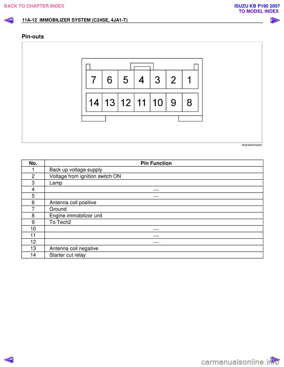
Pin-outs
RUW 48HSF000201
No. Pin Function
1 Back up voltage supply
2 Voltage from ignition switch ON
3 Lamp
4
5
6 Antenna coil positive
7 Ground
8 Engine immobilizer unit
9 To Tech2
10
11
12
13 Antenna coil negative
14 Starter cut relay
BACK TO CHAPTER INDEX TO MODEL INDEX
ISUZU KB P190 2007
Page 5924 of 6020

11A-26 IMMOBILIZER SYSTEM (C24SE, 4JA1-T)
Data List
No.
No.No.
No.
Strings
StringsStrings
Strings
Note
NoteNote
Note
1 Ignition Status
On 12V /Off 0V
2 Transponder-Key Transp. Key #
The number of the key currently
programmed
3 Transponder Status Correct/Incorrect TP-Key
4 Transponder-Key 1 Status Programmed / Not Programmed
5 Transponder-Key 2 Status Programmed / Not Programmed
6 Transponder-Key 3 Status Programmed / Not Programmed
7 Transponder-Key 4 Status Programmed / Not Programmed
8 Transponder-Key 5 Status Programmed / Not Programmed
9
Immobilizer signal Transmitted / Not Transmitted
10 Engine Request Received / Not Received
11 Vehicle Speed Output Veh.
Speed signal
12 Immobilizer Relay
Active 0V / Inactive 12V
13 Security Wait Time
Active / Inactive
BACK TO CHAPTER INDEX TO MODEL INDEX
ISUZU KB P190 2007
Page 5925 of 6020

IMMOBILIZER SYSTEM (C24SE, 4JA1-T) 11A-27
Diagnostic procedure
• Once the cause of DTC is repaired or gone,
engine can be operated normally, and present
DTC becomes history code.
• History code is canceled by no repeat failure on 25
consequence ignition key on afterward.
• History code cannot be canceled by batter
y
connector disconnected.
Clearing Diagnostic Trouble Codes
IMPORTANT: Do not clear DTCs unless directed to do
so by the service information provided for each
diagnostic procedure. W hen DTCs are cleared, the
Failure Record data which may help diagnose an
intermittent fault will also be erased from memory.
Verifying Vehicle Repair
Verification of vehicle repair will be more
comprehensive for vehicles with immobilizer system
diagnostic. Following a repair, the technician should
perform the following steps:
1. Review and record the Fail Records for the DTC
which has been diagnosed.
2. Clear DTC(s).
3. Operate the vehicle within conditions noted in the
Fail Records.
4. Monitor the DTC status information for the DTC
which has been diagnosed until the diagnostic test
associated with that DTC runs.
Following these steps are very important in verifying
repairs on immobilizer systems. Failure to follow these
steps could result in unnecessary repairs.
Diagnostic Aids
Check the condition for system parts.
• Installation condition, poor connection, damage,
system parts malfunction. Harness, Fuse, Relay,
Immobilizer coil (antenna), Key, Meter, Immobilize
r
control unit (ICU), Engine control module (ECM).
NOTE: Breakage of immobilizer fuse does not operate
immobilizer system. Check engine lamp flashes at this
time.
Check the Electro-Magnetic Interference (EMI)
• Location of vehicle check
Move the vehicle to a new location and perform
the check again.
• Non-OEM Parts.
Switch is "OFF" or remove the Non-OEM parts and
perform the check again.
• Other
Remove the accessory and another key from key.
Check the other items.
• Battery voltage is low.
• Immobilizer programming functions.
Must be programmed immobilizer system.
• Registration for security code, immobilizer control
unit parts number.
• Key switch operation.
Immobilizer system may detect a history DTC b
y
the timing of ON-OFF of a key switch.
• Active the immobilizer system.
• Keyless entry system is malfunction.
• Anti theft system is malfunction.
Check the operation
Check the operation "Lock / unlock" by using transmitte
r
(key) on the vehicle.
BACK TO CHAPTER INDEX TO MODEL INDEX
ISUZU KB P190 2007
Page 5957 of 6020

ANTITHEFT SYSTEM 11B-3
Function of a keyless entry system
W ith a keyless entry system the car can be locked or
unlocked from any position around the car up to a
specified distance, by using the potable radio remote
transmitter inside key (remote key).
Status LED
W hile the system is in delay the alarm system is active
and LED flashes at 0.5Hz with or without activated
interior protection.
Hazard relay
The hazard warning lights will be activated by an
external relay. The output is low active.
Switches
All switches to ground. This makes it possible for failure
analysis to detect a short circuit or a broken wire to
each switch. To use this feature it is necessary to place
a 1.8k Ω resistor in parallel to the required switch.
Receiver
The receiver is integrated into the control unit.
To lower the idle current the receiver is equipped with a
standby mode. The antenna is integrated on the printed
circuit board.
Depending on the mounting position of the control unit
the antenna can be connected externally.
Range of communication
The range of communication between remote key and
receiver is intended to be least 3 m from centre of the
car.
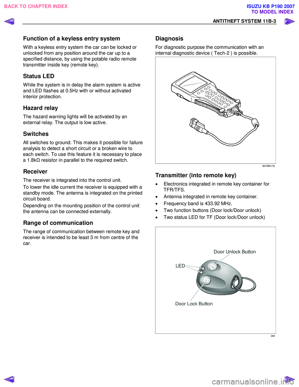
Diagnosis
For diagnostic purpose the communication with an
internal diagnostic device ( Tech-2 ) is possible.
901RW 176
Transmitter (into remote key)
• Electronics integrated in remote key container for
TFR/TFS.
• Antenna integrated in remote key container.
• Frequency band is 433.92 MHz.
• Two function buttons (Door lock/Door unlock)
• Two status LED for TF (Door lock/Door unlock)
OM
BACK TO CHAPTER INDEX TO MODEL INDEX
ISUZU KB P190 2007