relay ISUZU KB P190 2007 Workshop Repair Manual
[x] Cancel search | Manufacturer: ISUZU, Model Year: 2007, Model line: KB P190, Model: ISUZU KB P190 2007Pages: 6020, PDF Size: 70.23 MB
Page 5212 of 6020

8A-274 ELECTRICAL-BODY AND CHASSIS
2. Wiper dose not operate at “ INT “ position
Checkpoint Trouble Cause Countermeasure
Replace the wiper & washer
SW .
SW . malfunction
NG
Repair grounding point contact
Grounding point
C36 (RHD),
C2 (LHD)
Poor grounding point contact
Repair open circuit or
connector contact
Voltage between the
intermittent relay harness side
connector terminal 4
C3
and the ground at the “INT”
position (Should be battery
voltage present)
Open circuit or poor connector
contact
NG
NG
OK
OK
Continuity between the wiper
& washer SW connector
terminals 4
B59 and 2 B59
at the “ INT “ position
Replace the intermittent relay
Intermittent relay function
Relay malfunction
NG
OK
3. Wiper does not operate at “LO” position
Replace the wiper motor
W iper motor function
1. Disconnect the wiper & washer SW . connector
2. Turn the starter SW . on
3. Short-circuit between the wiper & washer SW .
harness side connector terminal 3
B59 and
5
B59 .
4. Check to see if the wiper
motor rotates at a low
speed
W iper motor malfunction
NG
Replace the wiper & washer
SW .
W iper & washer SW . function
SW . malfunction
NG
OK
BACK TO CHAPTER INDEX TO MODEL INDEXISUZU KB P190 2007
Page 5214 of 6020

8A-276 ELECTRICAL-BODY AND CHASSIS
6. Auto-stop function of the wiper motor does not operate
Checkpoint Trouble Cause Countermeasure
Repair open circuit or
connector contact
Open circuit or poor connector
contact
NG
Repair open circuit or
connector contact
Open circuit or poor connector
contact
NG Continuity between the
intermittent relay harness side
connector 6
C3 and the
wiper motor harness side
connector 6
C4
Replace the intermittent relay
Relay malfunction
NG
Intermittent relay function
W iper motor function
1. Disconnect the wiper motor connector
2. Connect the motor connector 5
B59 to the
battery (+) terminal and
1
C4 to the (-) terminal,
and then change the
connection of the battery (+)
terminal to the connector
4
C4 while the motor
rotating at a low speed
3. Check to see if the wiper motor stops at the auto stop
position when connecting
the connector terminals
3
C4 and 1 C4 in this
condition
Continuity between the wiper
& washer SW . connector
terminals 5
B59 and 6 B59
at the “OFF” position
OK
Replace the wiper motor
W iper motor malfunction
NG
Repair an open circuit or a
poor connection of the
connectors between the fuse
No. C9 (20A) and 4
C4
Voltage between the wiper
motor harness side connector
terminal 4
C4 and the
ground (Should be battery
v oltage present)
Open circuit or poor connector
contact
NG
OK
OK
OK
BACK TO CHAPTER INDEX
TO MODEL INDEXISUZU KB P190 2007
Page 5303 of 6020

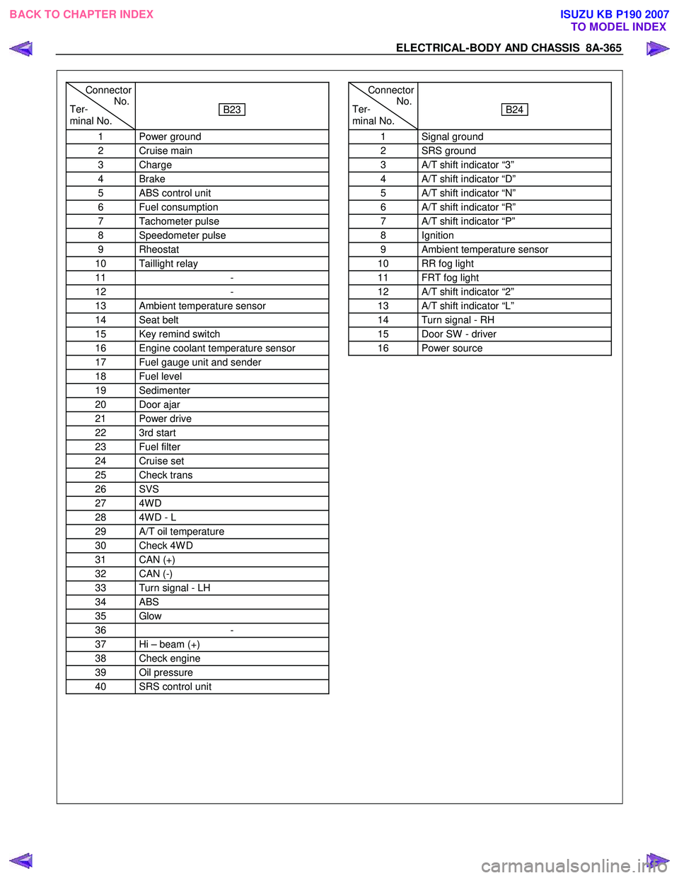
ELECTRICAL-BODY AND CHASSIS 8A-365
Connector
Ter- No.
minal No.
B23
1 Power ground
2 Cruise main
3 Charge
4 Brake
5 ABS control unit
6 Fuel consumption
7 Tachometer pulse
8 Speedometer pulse
9 Rheostat
10 Taillight relay
11 -
12 -
13 Ambient temperature sensor
14 Seat belt
15 Key remind switch
16 Engine coolant temperature sensor
17 Fuel gauge unit and sender
18 Fuel level
19 Sedimenter
20 Door ajar
21 Power drive
22 3rd start
23 Fuel filter
24 Cruise set
25 Check trans
26 SVS
27 4W D
28 4W D - L
29 A/T oil temperature
30 Check 4W D
31 CAN (+)
32 CAN (-)
33 Turn signal - LH
34 ABS
35 Glow
36 -
37 Hi – beam (+)
38 Check engine
39 Oil pressure
40 SRS control unit
Connector
Ter- No.
minal No.
B24
1 Signal ground
2 SRS ground
3 A/T shift indicator “3”
4 A/T shift indicator “D”
5 A/T shift indicator “N”
6 A/T shift indicator “R”
7 A/T shift indicator “P”
8 Ignition
9 Ambient temperature sensor
10 RR fog light
11 FRT fog light
12 A/T shift indicator “2”
13 A/T shift indicator “L”
14 Turn signal - RH
15 Door SW - driver
16 Power source
BACK TO CHAPTER INDEX TO MODEL INDEXISUZU KB P190 2007
Page 5304 of 6020

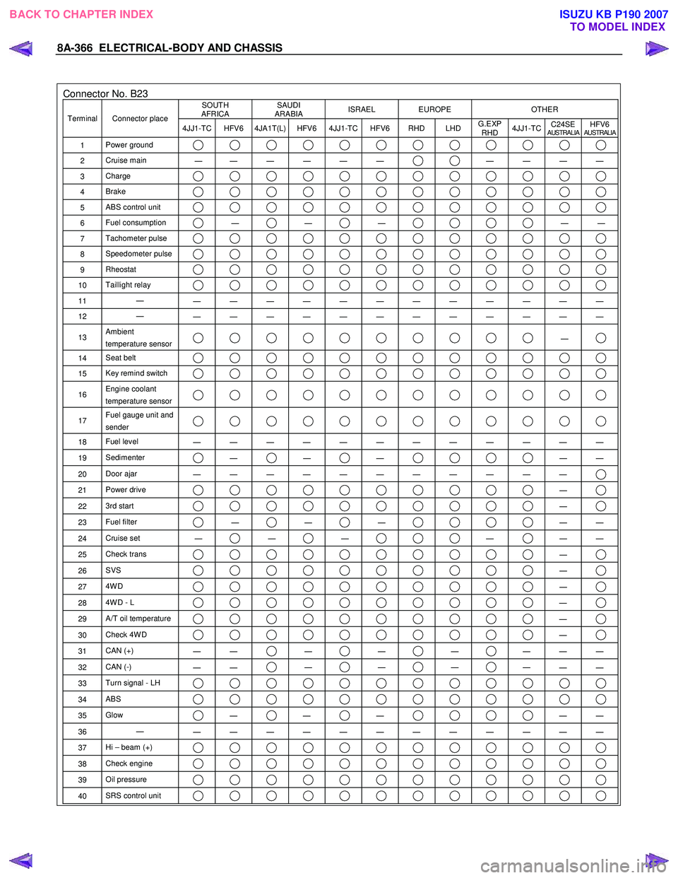
8A-366 ELECTRICAL-BODY AND CHASSIS
Connector No. B23 SOUTH
AFRICA SAUDI
ARABIA ISRAEL EUROPE OTHER
Terminal Connector place
4JJ1-TC HFV6 4JA1T(L) HFV6 4JJ1-TC HFV6 RHD LHD G.EXP
RHD 4JJ1-TC
C24SE
AUSTRALIAHFV6AUSTRALIA
1
Power ground
2 Cruise main
―
― ― ― ― ― ― ― ― ―
3
Charge
4 Brake
5 ABS control unit
6 Fuel consumption ―
―
―
―
―
7 Tachometer pulse
8 Speedometer pulse
9 Rheostat
10 Taillight relay
11 ―
― ― ― ― ― ― ― ― ― ― ― ―
12 ―
― ― ― ― ― ― ― ― ― ― ― ―
13 Ambient
temperature sensor ―
14 Seat belt
15 Key remind switch
16 Engine coolant
temperature sensor
17 Fuel gauge unit and
sender
18 Fuel level
― ― ― ― ― ― ― ― ― ― ― ―
19 Sedimenter ―
―
―
―
―
20 Door ajar
― ― ― ― ― ― ― ― ― ― ―
21 Power drive ―
22 3rd start ―
23 Fuel filter ―
―
―
―
―
24 Cruise set
― ―
―
―
―
―
25 Check trans ―
26 SVS ―
27 4W D ―
28 4W D - L ―
29 A/T oil temperature ―
30 Check 4W D ―
31 CAN (+)
― ― ―
―
―
― ― ―
32
CAN (-)
― ― ―
―
―
― ― ―
33
Turn signal - LH
34 ABS
35 Glow ―
―
―
―
―
36 ―
― ― ― ― ― ― ― ― ― ― ― ―
37 Hi – beam (+)
38 Check engine
39 Oil pressure
40 SRS control unit
BACK TO CHAPTER INDEX
TO MODEL INDEXISUZU KB P190 2007
Page 5365 of 6020

ELECTRICAL-BODY AND CHASSIS 8A-427
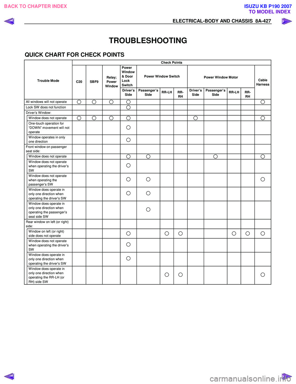
TROUBLESHOOTING
QUICK CHART FOR CHECK POINTS
Check Points
Trouble Mode Power
Window
& Door
Lock
Switch Power Window Switch
Power Window Motor
Driver’s
Side Passenger’s
Side RR-LH RR-
RH Driver’s
Side Passenger’s
Side RR-LH RR-
RH
All windows will not operate
Lock SW does not function Driver’s W indow:
W indow does not operate One-touch operation for
“DOW N” movement will not
operate
W indow operates in only
one direction
Front window on passenger
seat side:
W indow does not operate
W indow does not operate
when operating the driver’s
SW
W indow does not operate
when operating the
passenger’s SW
W indow does operate in
only one direction when
operating the driver’s SW
W indow does operate in
only one direction when
operating the passenger’s
seat side SW
Rear window on left (or right)
side:
W indow on left (or right)
side does not operate
W indow does not operate
when operating the driver’s
SW
W indow does operate in
only one direction when
operating the driver’s SW
W indow does operate in
only one direction when
operating the RR-LH (or
RH) side SW
Cable
Harness
Relay;
Power
Window
SBF9
C20
BACK TO CHAPTER INDEX TO MODEL INDEXISUZU KB P190 2007
Page 5366 of 6020

8A-428 ELECTRICAL-BODY AND CHASSIS
1. All windows do not operate
Checkpoint Trouble Cause Countermeasure
Reinstall or replace the fuse
C20 (30A)
Poor fuse contact or blown
NG
Replace the circuit breaker
C20 (50A or 60A)
C20 (50A or 60A Fuse box)
function
Circuit breaker malfunction
Repair grounding points
contact
Grounding points C2
Poor grounding point contact
NG
NG
OK
OK
OK
Fuse C20 (30A, Fuse box)
Replace the power window
relay
Power window relay
malfunction
NG
Repair an open circuit or a
poor connection of the
connectors between 1
C108
and 2
B8
Voltage between the power
window relay harness side
connector terminal 2
B8
and the ground (Should be
battery v oltage present)
Open circuit or poor connector
contact
NG
OK
Power window relay function
OK
Repair an open circuit or a
poor connection of the
connectors between 1
B8
and 1
B56 and 6 D5
Open circuit or poor connector
contact
NG Voltage between 6 D5 and
the ground (Should be battery
v oltage present)
OK
Repair an open circuit or a
poor connection of the
connectors between 3
D5
and
C2 , or 3 B8 (12
C107 ) and C109
Open circuit or poor connector
contact
NG
Continued on the next page
Voltage between 3
D5 or 3
B8 and the ground
BACK TO CHAPTER INDEX TO MODEL INDEXISUZU KB P190 2007
Page 5372 of 6020

8A-434 ELECTRICAL-BODY AND CHASSIS
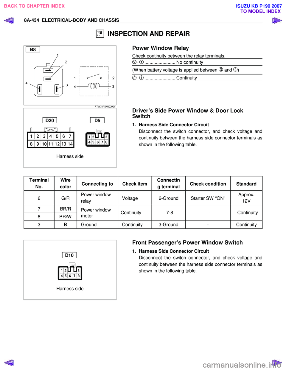
INSPECTION AND REPAIR
B8
RTW 78ASH002901
Power Window Relay
Check continuity between the relay terminals.
2- 1........................ No continuity
(W hen battery voltage is applied between
3 and 4)
2- 1........................ Continuity
Harness side
D20 D5
Driver’s Side Power Window & Door Lock
Switch
1. Harness Side Connector Circuit
Disconnect the switch connector, and check voltage and continuity between the harness side connector terminals as
shown in the following table.
Terminal No. Wire
color Connecting to Check item Connectin
g terminal Check condition Standard
6 G/R Power window
relay Voltage 6-Ground Starter SW “ON” Approx.
12V
7 BR/R Power window
8 BR/W motor
3 B Ground Continuity 3-Ground - Continuity
Harness side
D10
Front Passenger’s Power Window Switch
1. Harness Side Connector Circuit
Disconnect the switch connector, and check voltage and continuity between the harness side connector terminals as
shown in the following table.
Continuity
-
7-8
Continuity
BACK TO CHAPTER INDEX
TO MODEL INDEXISUZU KB P190 2007
Page 5373 of 6020

ELECTRICAL-BODY AND CHASSIS 8A-435
Terminal No. Wire
color Connecting to Check item Connectin
g terminal Check condition Standard
6 G/R Power window
relay Voltage 6-Ground Starter SW “ON” Approx.
12V
8 BR/R
7 BR/W Power window
motor Continuity 8-7
- Continuity
1,3 B Ground Continuity 1,3-Ground - Continuity
Harness side
D12 D16
Rear Power Window Switch-LH & RH
1. Harness Side Connector Circuit
Disconnect the switch connector, and check voltage and continuity between the harness side connector terminals as
shown in the following tables.
D12 (RR-LH)
Terminal No. Wire
color Connecting to Check item Connectin
g terminal Check condition Standard
6 G/R Power window
relay Voltage 6-Ground Starter SW “ON” Approx.
12V
8 BR/R
7 BR/W Power window
motor Continuity 8-7
- Continuity
3 B
4 B Ground Continuity 3,4-Ground - Continuity
D16 (RR-RH)
Terminal
No. Wire
color Connecting to Check item Connectin
g terminal Check condition Standard
6 G/R Power window
relay Voltage 6-Ground Starter SW “ON” Approx.
12V
8 BR/R
7 BR/W Power window
motor Continuity 8-7
- Continuity
3 B Ground Continuity 3-Ground - Continuity
BACK TO CHAPTER INDEX
TO MODEL INDEXISUZU KB P190 2007
Page 5424 of 6020

8A-486 ELECTRICAL-BODY AND CHASSIS
TROUBLE SHOOTING
Rear defogger inoperative
Checkpoint Trouble Cause Countermeasure
Reinstall or replace the fuse
No. C7 (10A) and 9
B56
Poor fuse contact or blown
NG
Reinstall or replace the fuse
C18 (20A)
C18 (20A, Fuse box)
Poor fuse contact or blown
Replace the rear defogger
switch
Rear defogger switch function
Switch malfunction
NG
NG
OK
OK
OK
Fuse No. C3 (10A, Fuse box)
and 9
B56
Replace the rear defogger
relay
Relay malfunction
NG
Continued on the next page
Rear defogger relay function
Repair grounding point contact
Grounding point
C2
Poor grounding point contact
NG
OK
Repair open circuit or poor
connector contact between
fuse No. C3 (10A) and 3
B7 , C18 (20A) and 1
B7 , 2 B7 (3 B55) and
1
L4 , 4 B7 (3 B54)
and 3
B46 or 1 B46 and
C2
Voltage between 1 L4 -
ground when the starter switch
and the rear defogger switch
are at on position (should be
battery voltage present)
Open circuit or poor connector
contact
NG
OK
BACK TO CHAPTER INDEX
TO MODEL INDEXISUZU KB P190 2007
Page 5427 of 6020

ELECTRICAL-BODY AND CHASSIS 8A-489
INSPECTION AND REPAIR
Switch side
B57
REAR DEFOGGER SWITCH
Rear Defogger Switch Connections
Terminal No.
SW position 9 7 8
ON
OFF
B7
RTW 78ASH002901
REAR DEFOGGER RELAY
Check continuity between the relay terminals.
2- 1........................ No continuity
(W hen battery voltage is applied between 4 and 3)
2- 1........................ Continuity
INSPECTION OF REAR DEFOGGER HEAT
WIRE
• Heat wires are printed on the inner side of glass.
To clean, use a soft cloth and wipe horizontally along the wires.
• Never use glass cleaner or equivalent.
• W hen measuring voltage, wind a piece of tin foil around the
tip of the negative probe and press the foil against the wire
with your finger as shown.
(1) Turn the ignition switch on.
(2) Turn the defogger switch on.
(3) Measure the voltage between the three points on the heat wire and the (-) terminal with a voltmeter.
(4) Check that the voltage becomes smaller from
A to B to C.
(5) If there is a place where the voltage suddenly changes to
0V, there is a broken wire between there and the powe
r
side.
(6) Move the tester probe from the position where the voltage changes to 0V toward the power side and find where the
voltage suddenly increases.
BACK TO CHAPTER INDEX TO MODEL INDEXISUZU KB P190 2007