lock ISUZU KB P190 2007 Workshop Repair Manual
[x] Cancel search | Manufacturer: ISUZU, Model Year: 2007, Model line: KB P190, Model: ISUZU KB P190 2007Pages: 6020, PDF Size: 70.23 MB
Page 2538 of 6020

Engine Mechanical – V6 Page 6A1–59
3.5 Accessory Drive Belt
RWD Vehicle
Remove
1 Remove the air intake duct from between the air flow meter and the throttle body, refer to 6C1-3 Engine
Management – V6 – Service Operations.
2 Note the accessory drive belt (1) routing.
Figure 6A1 – 29
3 Using a suitable ½” drive socket bar (1), rotate the drive belt tensioner (2) clockwise, to reduce belt
tension.
4 W hile holding the tensioner in the reduced tension position, remove the accessory drive belt (3).
NOTE
If required use an assistant to maintain the tensioner in the required position.
CAUTION
If running the engine with the accessory
drive belt removed, the coolant pump will
not be operating and the engine may
overheat if left unsupervised even for a short
period.
Figure 6A1 – 30
Reinstall
1 Install the drive belt over the A/C compressor, idler pulley, power steering pump, coolant pump, generator and tensioner pulleys.
2 Using a suitable ½” drive socket bar (1), rotate the drive belt tensioner (2) clockwise, refer to Figure 6A1 – 30.
3 W ith an assistant holding the tensioner in the required position, feed the accessory drive belt (3) over the crankshaft pulley.
4 Slowly release the drive belt tensioner mechanism.
BACK TO CHAPTER INDEX
TO MODEL INDEX
ISUZU KB P190 2007
Page 2541 of 6020
Engine Mechanical – V6 Page 6A1–62
3.8 Power Steering Pump Bracket
Remove
1 Remove the power steering pump and reservoir, refer to 3B_Steering.
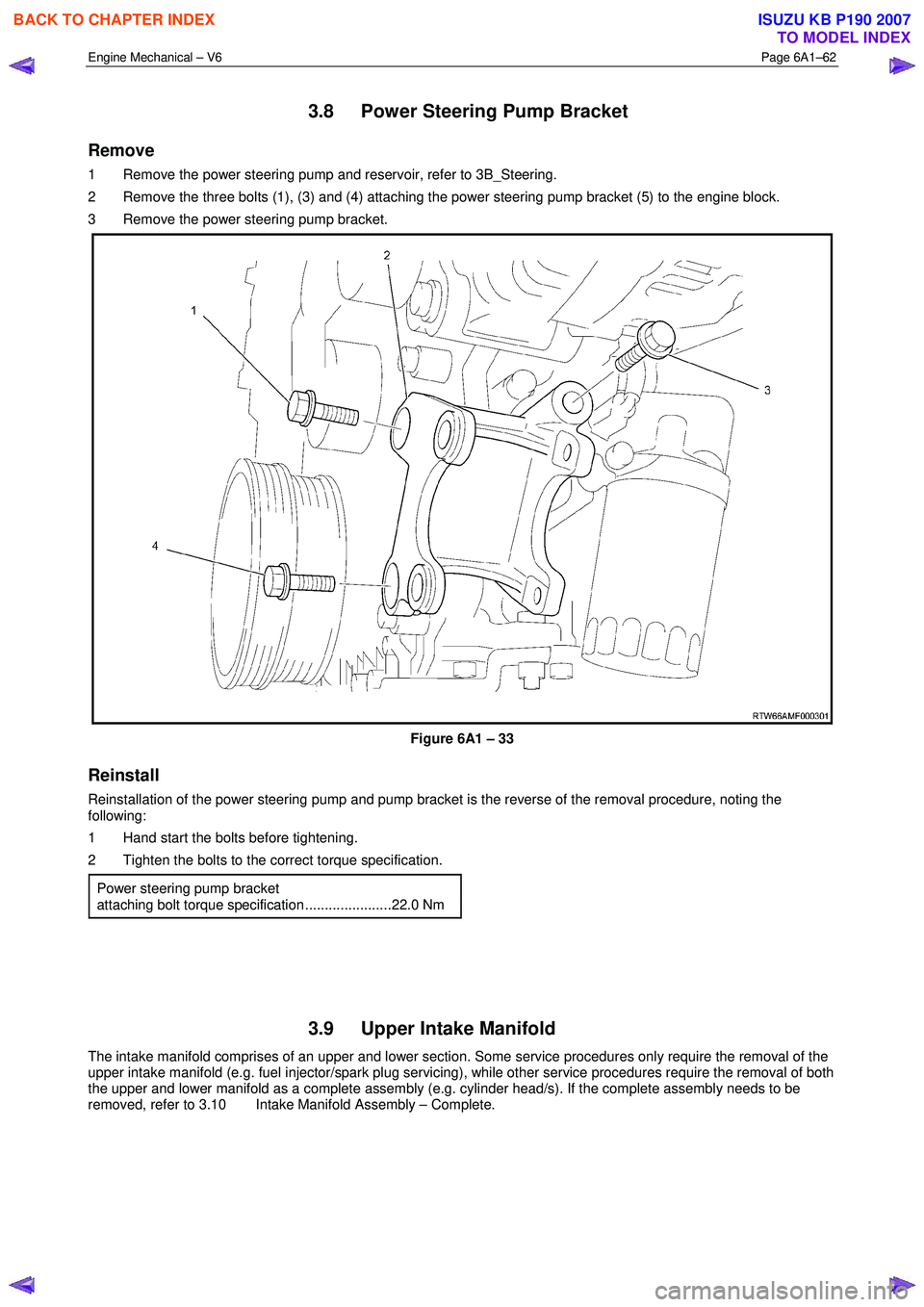
2 Remove the three bolts (1), (3) and (4) attaching the power steering pump bracket (5) to the engine block.
3 Remove the power steering pump bracket.
Figure 6A1 – 33
Reinstall
Reinstallation of the power steering pump and pump bracket is the reverse of the removal procedure, noting the
following:
1 Hand start the bolts before tightening.
2 Tighten the bolts to the correct torque specification.
Power steering pump bracket
attaching bolt torque specification ......................22.0 Nm
3.9 Upper Intake Manifold
The intake manifold comprises of an upper and lower section. Some service procedures only require the removal of the
upper intake manifold (e.g. fuel injector/spark plug servicing), while other service procedures require the removal of both
the upper and lower manifold as a complete assembly (e.g. cylinder head/s). If the complete assembly needs to be
removed, refer to 3.10 Intake Manifold Assembly – Complete.
BACK TO CHAPTER INDEX
TO MODEL INDEX
ISUZU KB P190 2007
Page 2543 of 6020
Engine Mechanical – V6 Page 6A1–64
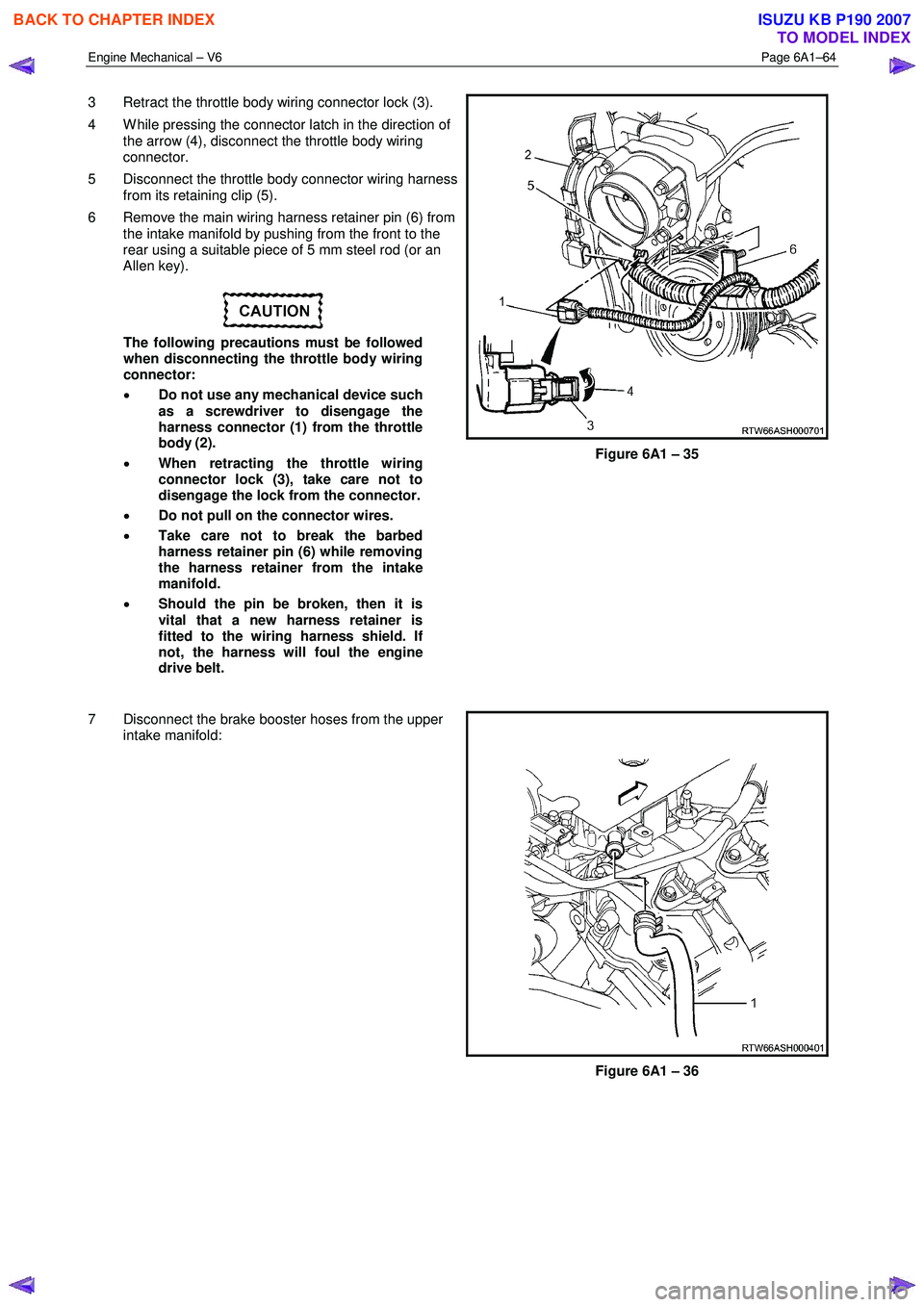
3 Retract the throttle body wiring connector lock (3).
4 W hile pressing the connector latch in the direction of the arrow (4), disconnect the throttle body wiring
connector.
5 Disconnect the throttle body connector wiring harness from its retaining clip (5).
6 Remove the main wiring harness retainer pin (6) from the intake manifold by pushing from the front to the
rear using a suitable piece of 5 mm steel rod (or an
Allen key).
The following precautions must be followed
when disconnecting the throttle body wiring
connector:
• Do not use any mechanical device such
as a screwdriver to disengage the
harness connector (1) from the throttle
body (2).
• When retracting the throttle wiring
connector lock (3), take care not to
disengage the lock from the connector.
• Do not pull on the connector wires.
• Take care not to break the barbed
harness retainer pin (6) while removing
the harness retainer from the intake
manifold.
• Should the pin be broken, then it is
vital that a new harness retainer is
fitted to the wiring harness shield. If
not, the harness will foul the engine
drive belt.
Figure 6A1 – 35
7 Disconnect the brake booster hoses from the upper intake manifold:
Figure 6A1 – 36
BACK TO CHAPTER INDEX
TO MODEL INDEX
ISUZU KB P190 2007
Page 2547 of 6020
Engine Mechanical – V6 Page 6A1–68
CAUTION
Tighten the intake manifold bolts in a circular
pattern starting at the centre bolt and moving
outward.
2 Ensure that all fasteners are tightened to the correct torque specification. Upper intake manifold to lower
intake manifold attaching bolt
torque specification ............................................23.0 Nm
Upper intake manifold to
cylinder head attaching bolt
torque specification ............................................23.0 Nm
Incorrect wiring connector installation may
cause component malfunction or component
damage.
3 Ensure all wiring connectors are fully engaged and if applicable, locked in place.
4 Ensure all wiring harnesses are correctly routed and attached securely in their retaining clips.
5 Ensure that all hoses and pipes are routed correctly and that any retaining clips are correctly installed.
6 Start and run the engine to check for correct operation.
3.10 Intake Manifold Assembly – Complete
The intake manifold comprises of an upper and lower section. Some service procedures only require the removal of the
upper intake manifold (e.g. fuel injector/spark plug servicing), while other service procedures require the removal of both
the upper and lower manifold as a complete assembly (e.g. cylinder head/s). If only the upper intake manifold needs to
be removed, refer to 3.9 Upper Intake Manifold.
Remove
Disconnection of the battery affects certain
vehicle electronic systems. Refer to 1.1
WARNING, CAUTION and NOTES before
disconnecting the battery.
1 Depressurise the fuel system.
2 Disconnect the battery negative terminal.
BACK TO CHAPTER INDEX
TO MODEL INDEX
ISUZU KB P190 2007
Page 2548 of 6020
Engine Mechanical – V6 Page 6A1–69
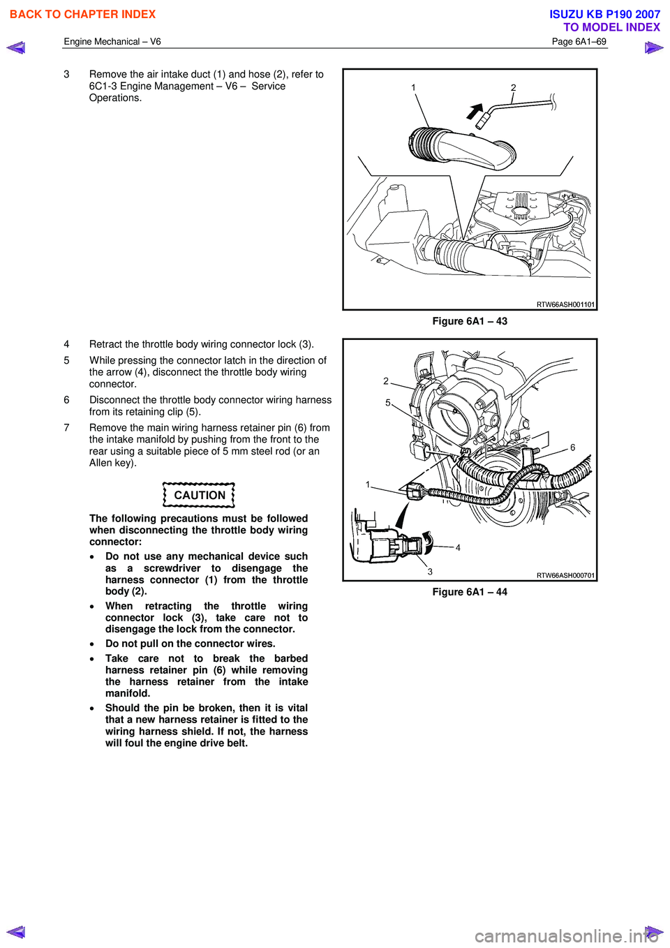
3 Remove the air intake duct (1) and hose (2), refer to
6C1-3 Engine Management – V6 – Service
Operations.
Figure 6A1 – 43
4 Retract the throttle body wiring connector lock (3).
5 W hile pressing the connector latch in the direction of the arrow (4), disconnect the throttle body wiring
connector.
6 Disconnect the throttle body connector wiring harness from its retaining clip (5).
7 Remove the main wiring harness retainer pin (6) from the intake manifold by pushing from the front to the
rear using a suitable piece of 5 mm steel rod (or an
Allen key).
The following precautions must be followed
when disconnecting the throttle body wiring
connector:
• Do not use any mechanical device such
as a screwdriver to disengage the
harness connector (1) from the throttle
body (2).
• When retracting the throttle wiring
connector lock (3), take care not to
disengage the lock from the connector.
• Do not pull on the connector wires.
• Take care not to break the barbed
harness retainer pin (6) while removing
the harness retainer from the intake
manifold.
• Should the pin be broken, then it is vital
that a new harness retainer is fitted to the
wiring harness shield. If not, the harness
will foul the engine drive belt.
Figure 6A1 – 44
BACK TO CHAPTER INDEX
TO MODEL INDEX
ISUZU KB P190 2007
Page 2554 of 6020
Engine Mechanical – V6 Page 6A1–75
CAUTION
Tighten the intake manifold bolts in a circular
pattern starting at the centre bolt and moving
outward.
4 Ensure that all fasteners are tightened to the correct torque specification. Upper intake manifold to lower intake
manifold attaching bolt torque specification .......23.0 Nm
Upper intake manifold to cylinder
head attaching bolt torque specification .............23.0 Nm
Lower intake manifold to cylinder
head attaching bolt torque specification .............23.0 Nm
Fuel injector wiring harness bracket
attaching bolt torque specification ........................9.0 Nm
Incorrect wiring connector installation may
cause component malfunction or component
damage.
5 Ensure all wiring connectors are fully engaged and if applicable, locked in place.
6 Ensure all wiring harnesses are correctly routed and attached securely in their retaining clips.
7 Ensure that all hoses and pipes are routed correctly and that any retaining clips are correctly installed.
8 After installation pull on any quick connect fittings to check that each is correctly installed.
9 Start and run the engine to check for correct operation.
3.11 Exhaust Manifold Assembly
Remove
Allow the engine to cool before commencing.
Disconnection of the battery affects certain
vehicle electronic systems, refer to 1.1
WARNING, CAUTION and NOTES before
disconnecting the battery.
1 Disconnect the battery negative terminal.
BACK TO CHAPTER INDEX
TO MODEL INDEX
ISUZU KB P190 2007
Page 2571 of 6020
Engine Mechanical – V6 Page 6A1–92
Reinstall
Reinstallation of the front cover is the reverse of the removal procedure, noting the following:
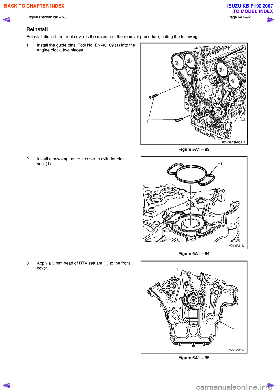
1 Install the guide pins, Tool No. EN-46109 (1) into the engine block, two places.
Figure 6A1 – 93
2 Install a new engine front cover to cylinder block seal (1).
Figure 6A1 – 94
3 Apply a 3 mm bead of RTV sealant (1) to the front cover.
Figure 6A1 – 95
BACK TO CHAPTER INDEX
TO MODEL INDEX
ISUZU KB P190 2007
Page 2572 of 6020
Engine Mechanical – V6 Page 6A1–93
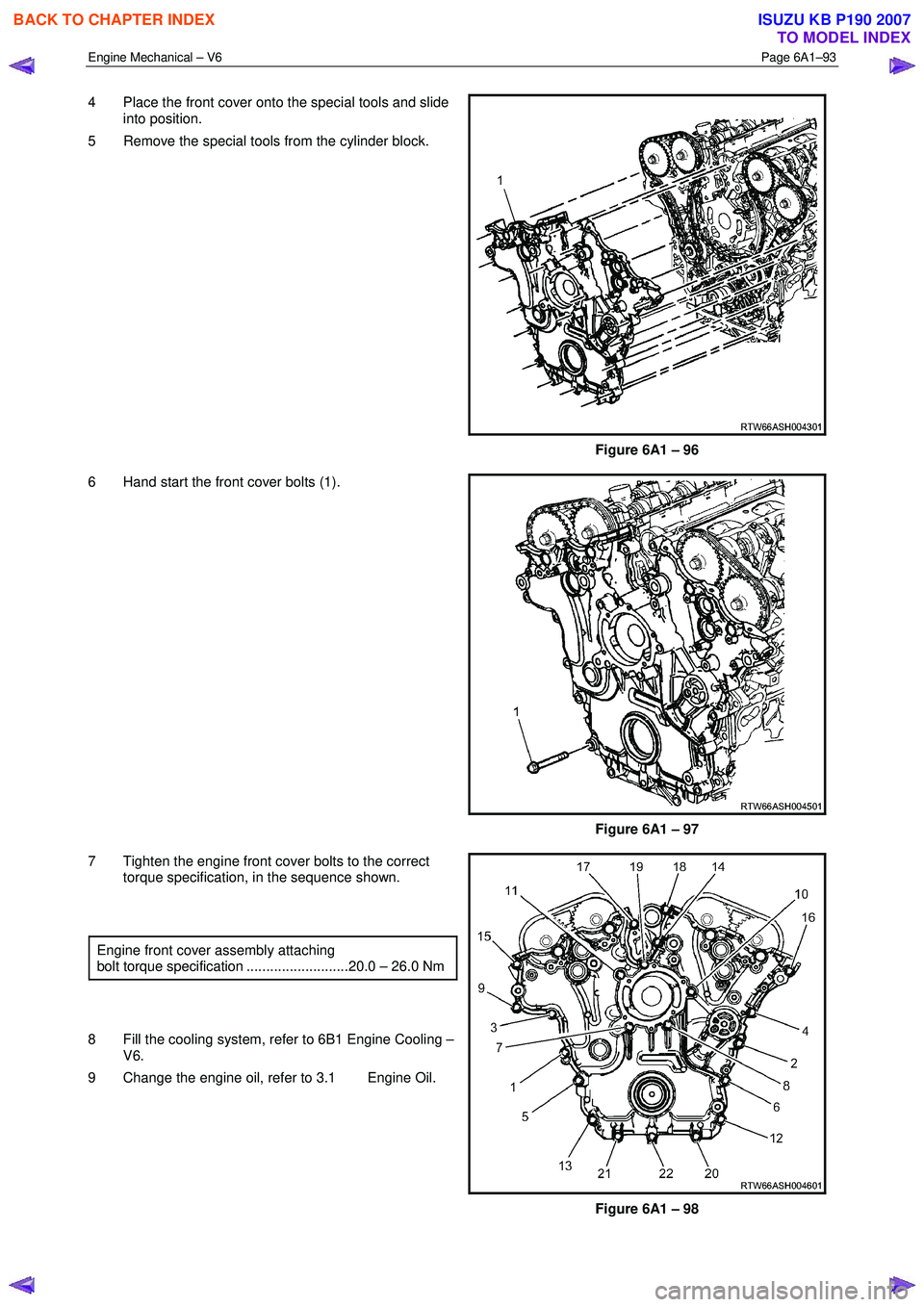
4 Place the front cover onto the special tools and slide
into position.
5 Remove the special tools from the cylinder block.
Figure 6A1 – 96
6 Hand start the front cover bolts (1).
Figure 6A1 – 97
7 Tighten the engine front cover bolts to the correct torque specification, in the sequence shown.
Engine front cover assembly attaching
bolt torque specification ..........................20.0 – 26.0 Nm
8 Fill the cooling system, refer to 6B1 Engine Cooling – V6.
9 Change the engine oil, refer to 3.1 Engine Oil.
Figure 6A1 – 98
BACK TO CHAPTER INDEX
TO MODEL INDEX
ISUZU KB P190 2007
Page 2575 of 6020
Engine Mechanical – V6 Page 6A1–96
Remove
Right-hand Secondary Timing Chain
CAUTION
After removing the upper intake manifold, and
spark plugs, plug any openings to prevent dirt
and other contaminants from entering.
1 Remove the engine front cover assembly, refer to 3.15 Front Cover Assembly.
2 Remove the spark plugs to aid crankshaft/engine rotation, refer to 6C1-3 Engine Management – V6 – Service Operations.
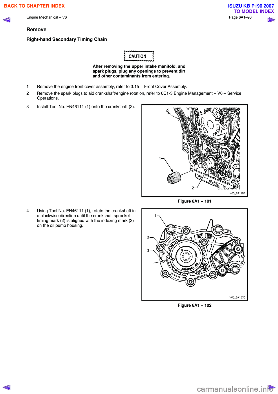
3 Install Tool No. EN46111 (1) onto the crankshaft (2).
Figure 6A1 – 101
4 Using Tool No. EN46111 (1), rotate the crankshaft in a clockwise direction until the crankshaft sprocket
timing mark (2) is aligned with the indexing mark (3)
on the oil pump housing.
Figure 6A1 – 102
BACK TO CHAPTER INDEX
TO MODEL INDEX
ISUZU KB P190 2007
Page 2579 of 6020
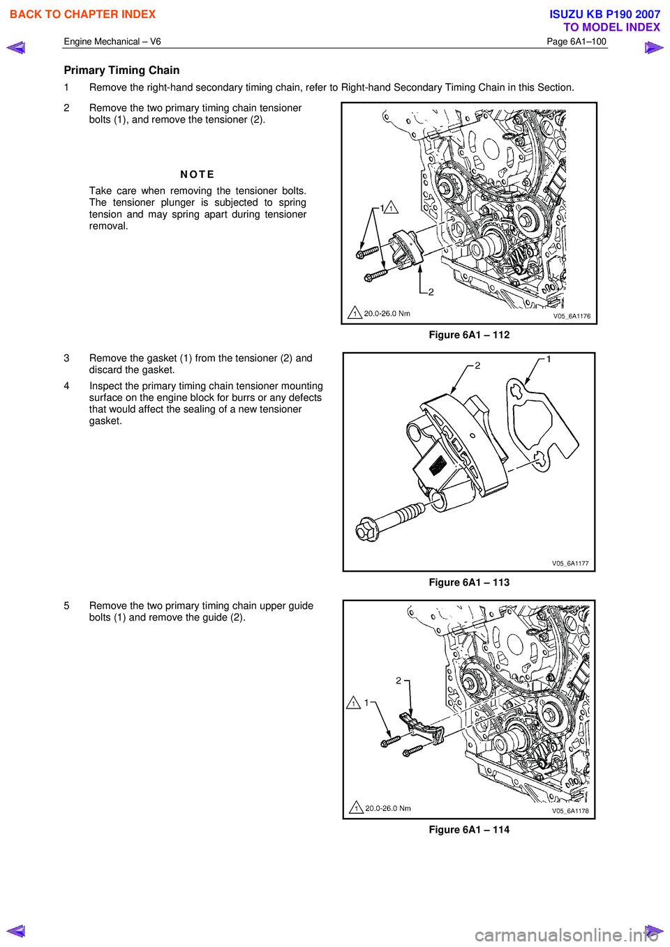
Engine Mechanical – V6 Page 6A1–100
Primary Timing Chain
1 Remove the right-hand secondary timing chain, refer to Right-hand Secondary Timing Chain in this Section.
2 Remove the two primary timing chain tensioner bolts (1), and remove the tensioner (2).
NOTE
Take care when removing the tensioner bolts.
The tensioner plunger is subjected to spring
tension and may spring apart during tensioner
removal.
Figure 6A1 – 112
3 Remove the gasket (1) from the tensioner (2) and discard the gasket.
4 Inspect the primary timing chain tensioner mounting surface on the engine block for burrs or any defects
that would affect the sealing of a new tensioner
gasket.
Figure 6A1 – 113
5 Remove the two primary timing chain upper guide bolts (1) and remove the guide (2).
Figure 6A1 – 114
BACK TO CHAPTER INDEX
TO MODEL INDEX
ISUZU KB P190 2007