lock ISUZU KB P190 2007 Workshop Repair Manual
[x] Cancel search | Manufacturer: ISUZU, Model Year: 2007, Model line: KB P190, Model: ISUZU KB P190 2007Pages: 6020, PDF Size: 70.23 MB
Page 2685 of 6020
Engine Mechanical – V6 Page 6A1–206
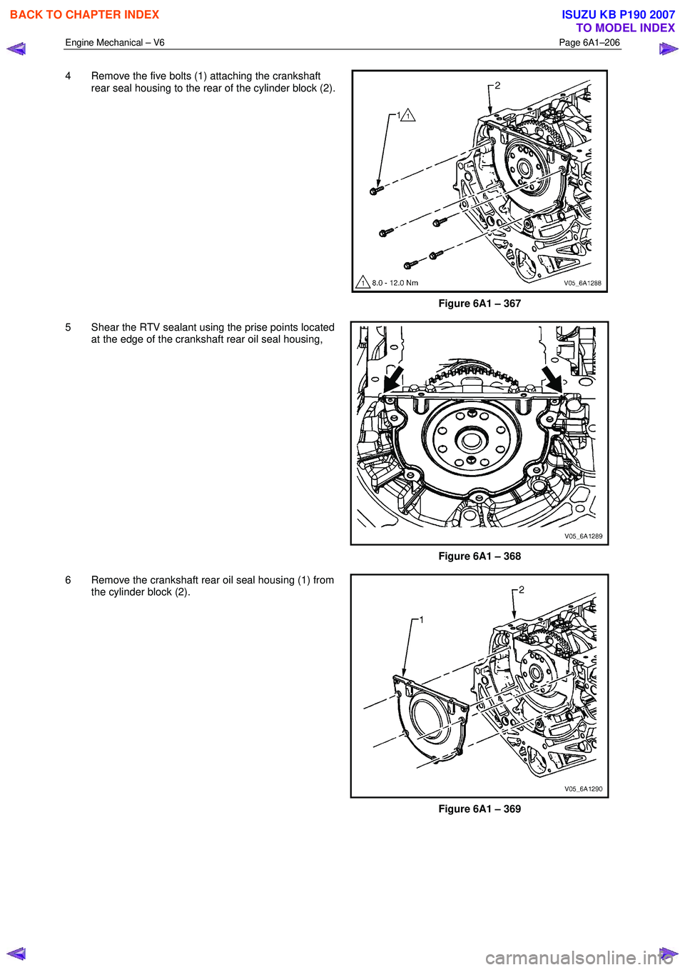
4 Remove the five bolts (1) attaching the crankshaft
rear seal housing to the rear of the cylinder block (2).
Figure 6A1 – 367
5 Shear the RTV sealant using the prise points located at the edge of the crankshaft rear oil seal housing,
Figure 6A1 – 368
6 Remove the crankshaft rear oil seal housing (1) from the cylinder block (2).
Figure 6A1 – 369
BACK TO CHAPTER INDEX
TO MODEL INDEX
ISUZU KB P190 2007
Page 2686 of 6020
Engine Mechanical – V6 Page 6A1–207
Reinstall
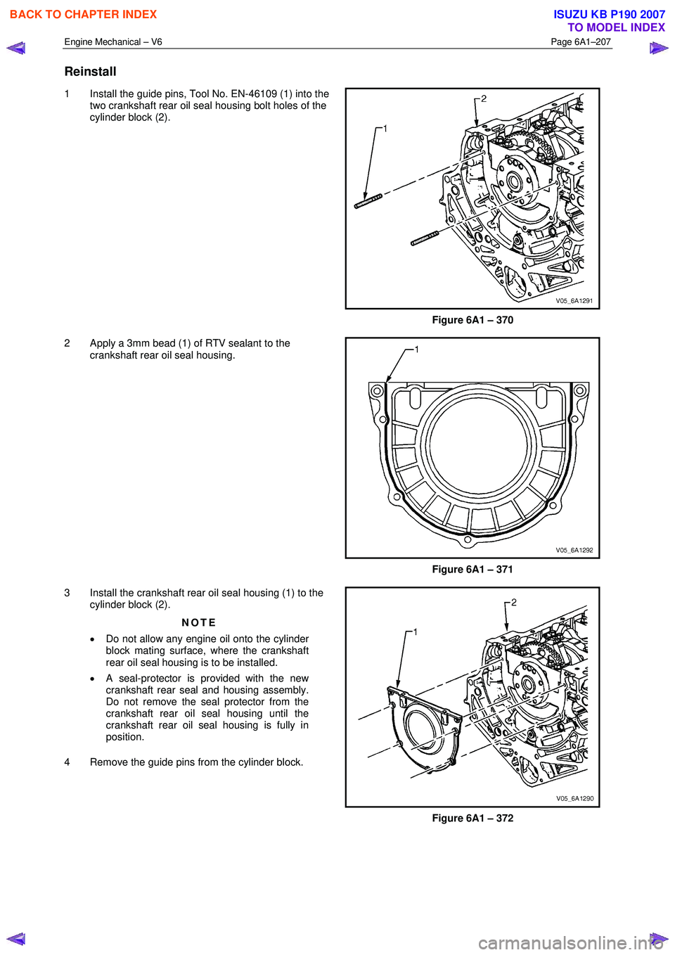
1 Install the guide pins, Tool No. EN-46109 (1) into the
two crankshaft rear oil seal housing bolt holes of the
cylinder block (2).
Figure 6A1 – 370
2 Apply a 3mm bead (1) of RTV sealant to the crankshaft rear oil seal housing.
Figure 6A1 – 371
3 Install the crankshaft rear oil seal housing (1) to the cylinder block (2).
NOTE
• Do not allow any engine oil onto the cylinder
block mating surface, where the crankshaft
rear oil seal housing is to be installed.
• A seal-protector is provided with the new
crankshaft rear seal and housing assembly.
Do not remove the seal protector from the
crankshaft rear oil seal housing until the
crankshaft rear oil seal housing is fully in
position.
4 Remove the guide pins from the cylinder block.
Figure 6A1 – 372
BACK TO CHAPTER INDEX
TO MODEL INDEX
ISUZU KB P190 2007
Page 2687 of 6020

Engine Mechanical – V6 Page 6A1–208
5 Install the crankshaft rear oil seal housing attaching
bolts (1) to the cylinder block (2) and tighten to the
correct torque specification.
Crankshaft rear oil seal housing
attaching bolt torque specification .............8.0 – 12.0 Nm
Figure 6A1 – 373
4.5 Pistons, Pins, Rings, Connecting Rods and Big-end Bearings
Remove
1 Remove the engine assembly, refer to 4.1 Engine .
2 Remove both cylinder head assemblies, refer to 3.22 Cylinder Head Assembly.
3 Remove the oil pan assembly, refer to 4.2 Oil Pan and Oil Pump Suction Pipe Assembly.
4 Mark the top of the piston being removed to identify its specific bore.
5 Install Tool No. EN-46111 (1) onto the crankshaft (2).
6 Rotate the crankshaft until the piston being removed is at the bottom of its stroke; bottom dead centre
(BDC).
Figure 6A1 – 374
CAUTION
If the connecting rod bearings have been
used in a running engine, they must be
replaced with new connecting rod bearings
for reassembly.
7 Before removing the connecting rods, check the connecting rod side clearance using the following procedure: a Tap the connecting rod to one end of the crankshaft journal with a dead blow or wooden hammer.
b Using feeler gauges, measure the clearance between the crankshaft counterweight and the connecting rod.
c The connecting rod side clearance should not exceed specifications, refer to 5 Specifications.
BACK TO CHAPTER INDEX
TO MODEL INDEX
ISUZU KB P190 2007
Page 2693 of 6020

Engine Mechanical – V6 Page 6A1–214
3 Using an inside micrometer, measure the piston pin
bore (1). Compare the result with the piston pin
diameter and piston pin to piston pin bore clearance
listed in the specifications, refer to 5 Specifications.
4 If the clearance is excessive, determine which piece is out of specification and replace as required.
5 Replace the piston if any of its dimensions are out of specification.
6 If the new piston does not meet clearance specifications, the cylinder block may need to be
oversized to 0.25 mm. There is only one size of
oversized pistons and rings available for service.
Figure 6A1 – 387
Piston Ring Measurement
1 Measure the piston ring end gap using the following procedure:
a Place the piston ring (1) in the area of the bore where the piston ring will travel, approximately 25 mm below
the deck surface. Ensure the ring is square with the
cylinder bore by positioning the ring with the piston
head.
b Measure the end gap of the piston ring with feeler gauges (2), refer to 5 Specifications.
c If the clearance exceeds the provided specifications, the piston rings must be replaced.
d Repeat the procedure for all piston rings.
Figure 6A1 – 388
2 Measure the piston ring side clearance using the following procedure:
a Roll the piston ring (1) entirely around the piston ring groove. If any binding is caused by the ring groove,
dress the groove with a fine file. If any binding is
caused by a distorted piston ring, replace the ring.
b W ith the piston ring on the piston, use feeler gauges (2) to check clearance at multiple locations.
c Compare the measurements with piston ring side clearance listed in the specifications, refer to 5
Specifications.
d If the clearance is greater than specifications, replace the piston rings.
Figure 6A1 – 389
BACK TO CHAPTER INDEX
TO MODEL INDEX
ISUZU KB P190 2007
Page 2694 of 6020
Engine Mechanical – V6 Page 6A1–215
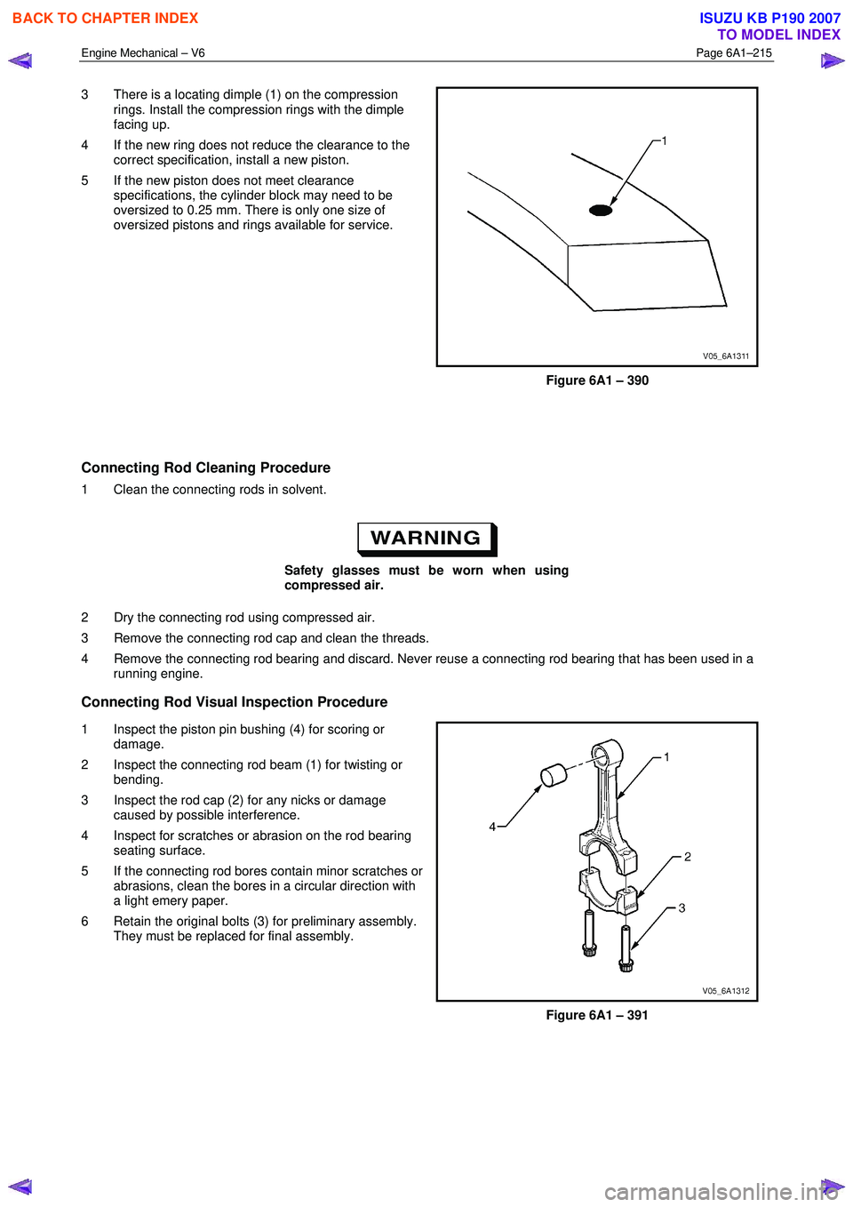
3 There is a locating dimple (1) on the compression
rings. Install the compression rings with the dimple
facing up.
4 If the new ring does not reduce the clearance to the correct specification, install a new piston.
5 If the new piston does not meet clearance specifications, the cylinder block may need to be
oversized to 0.25 mm. There is only one size of
oversized pistons and rings available for service.
Figure 6A1 – 390
Connecting Rod Cleaning Procedure
1 Clean the connecting rods in solvent.
Safety glasses must be worn when using
compressed air.
2 Dry the connecting rod using compressed air.
3 Remove the connecting rod cap and clean the threads.
4 Remove the connecting rod bearing and discard. Never reuse a connecting rod bearing that has been used in a running engine.
Connecting Rod Visual Inspection Procedure
1 Inspect the piston pin bushing (4) for scoring or
damage.
2 Inspect the connecting rod beam (1) for twisting or bending.
3 Inspect the rod cap (2) for any nicks or damage caused by possible interference.
4 Inspect for scratches or abrasion on the rod bearing seating surface.
5 If the connecting rod bores contain minor scratches or abrasions, clean the bores in a circular direction with
a light emery paper.
6 Retain the original bolts (3) for preliminary assembly. They must be replaced for final assembly.
Figure 6A1 – 391
BACK TO CHAPTER INDEX
TO MODEL INDEX
ISUZU KB P190 2007
Page 2698 of 6020
Engine Mechanical – V6 Page 6A1–219
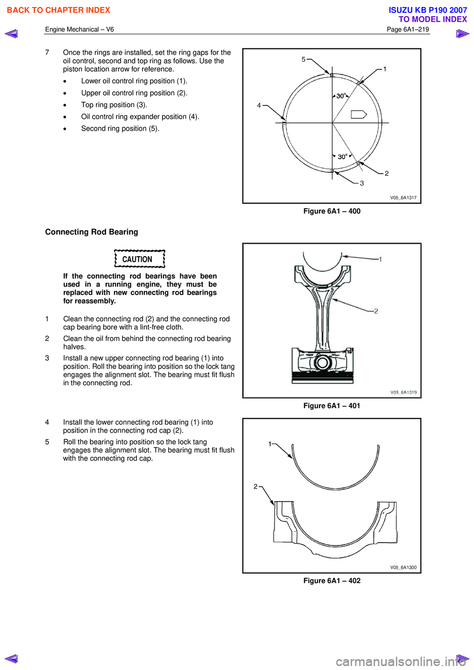
7 Once the rings are installed, set the ring gaps for the
oil control, second and top ring as follows. Use the
piston location arrow for reference.
• Lower oil control ring position (1).
• Upper oil control ring position (2).
• Top ring position (3).
• Oil control ring expander position (4).
• Second ring position (5).
Figure 6A1 – 400
Connecting Rod Bearing
CAUTION
If the connecting rod bearings have been
used in a running engine, they must be
replaced with new connecting rod bearings
for reassembly.
1 Clean the connecting rod (2) and the connecting rod cap bearing bore with a lint-free cloth.
2 Clean the oil from behind the connecting rod bearing halves.
3 Install a new upper connecting rod bearing (1) into position. Roll the bearing into position so the lock tang
engages the alignment slot. The bearing must fit flush
in the connecting rod.
Figure 6A1 – 401
4 Install the lower connecting rod bearing (1) into position in the connecting rod cap (2).
5 Roll the bearing into position so the lock tang engages the alignment slot. The bearing must fit flush
with the connecting rod cap.
Figure 6A1 – 402
BACK TO CHAPTER INDEX
TO MODEL INDEX
ISUZU KB P190 2007
Page 2699 of 6020
Engine Mechanical – V6 Page 6A1–220
Reinstall
Piston Connecting Rod and Connecting Rod Bearing Installation
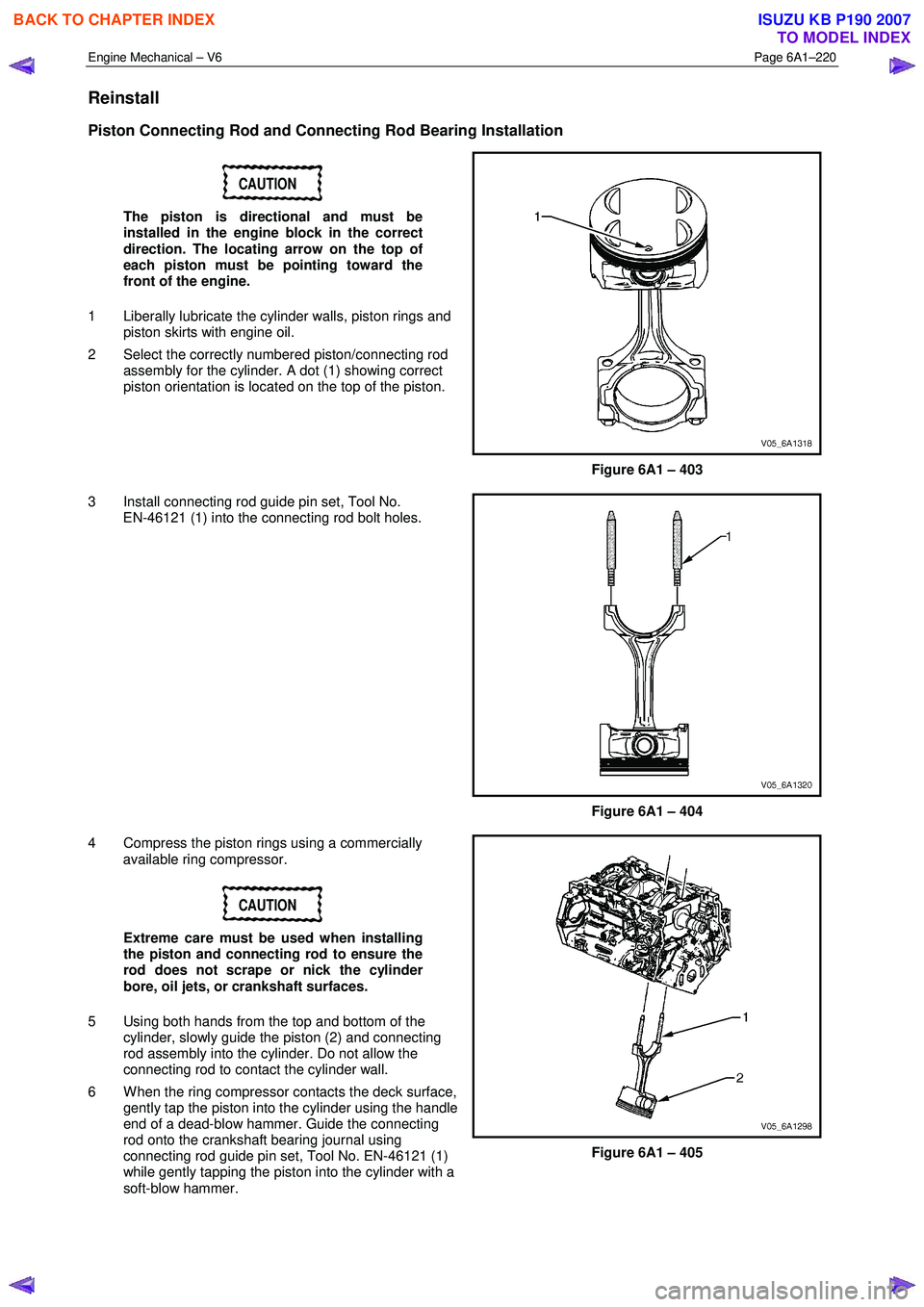
CAUTION
The piston is directional and must be
installed in the engine block in the correct
direction. The locating arrow on the top of
each piston must be pointing toward the
front of the engine.
1 Liberally lubricate the cylinder walls, piston rings and piston skirts with engine oil.
2 Select the correctly numbered piston/connecting rod assembly for the cylinder. A dot (1) showing correct
piston orientation is located on the top of the piston.
Figure 6A1 – 403
3 Install connecting rod guide pin set, Tool No. EN-46121 (1) into the connecting rod bolt holes.
Figure 6A1 – 404
4 Compress the piston rings using a commercially available ring compressor.
CAUTION
Extreme care must be used when installing
the piston and connecting rod to ensure the
rod does not scrape or nick the cylinder
bore, oil jets, or crankshaft surfaces.
5 Using both hands from the top and bottom of the cylinder, slowly guide the piston (2) and connecting
rod assembly into the cylinder. Do not allow the
connecting rod to contact the cylinder wall.
6 W hen the ring compressor contacts the deck surface, gently tap the piston into the cylinder using the handle
end of a dead-blow hammer. Guide the connecting
rod onto the crankshaft bearing journal using
connecting rod guide pin set, Tool No. EN-46121 (1)
while gently tapping the piston into the cylinder with a
soft-blow hammer.
Figure 6A1 – 405
BACK TO CHAPTER INDEX
TO MODEL INDEX
ISUZU KB P190 2007
Page 2700 of 6020

Engine Mechanical – V6 Page 6A1–221
7 Remove connecting rod guide pin set, Tool No.
EN-46121 (1) from the connecting rod bolt holes.
Figure 6A1 – 406
Connecting Rod Bearing Clearance Measurement Procedure
NOTE
Before final assembly, check the clearance of the
new connecting rod bearings.
1 Place a length of fresh, room temperature plastic gauging material all the way across the connecting
rod bearing journal.
2 Install the connecting rod bearing into the connecting rod cap.
3 Install the connecting rod end cap (1) on its original connecting rod and ensure the bearing lock tangs are
aligned on the same side of the rod.
Figure 6A1 – 407
NOTE
Reuse the old connecting rod bolts only for
measuring the connecting rod bearing clearance.
4 Install the connecting rod cap bolts into the connecting rod cap and tighten to the correct torque specification using torque angle wrench, Tool No. EN-7115.
Connecting rod cap attaching
bolt torque specification:
Stage 1 .........................30.0 Nm
Stage 2 ........ Loosen completely
Stage 3 .........................25.0 Nm
Stage 4 .................. 110 degrees
5 Allow the assembly to sit for at least 2 minutes.
6 Remove the connecting rod cap bolts and discard.
7 Remove the connecting rod cap.
BACK TO CHAPTER INDEX
TO MODEL INDEX
ISUZU KB P190 2007
Page 2701 of 6020
Engine Mechanical – V6 Page 6A1–222
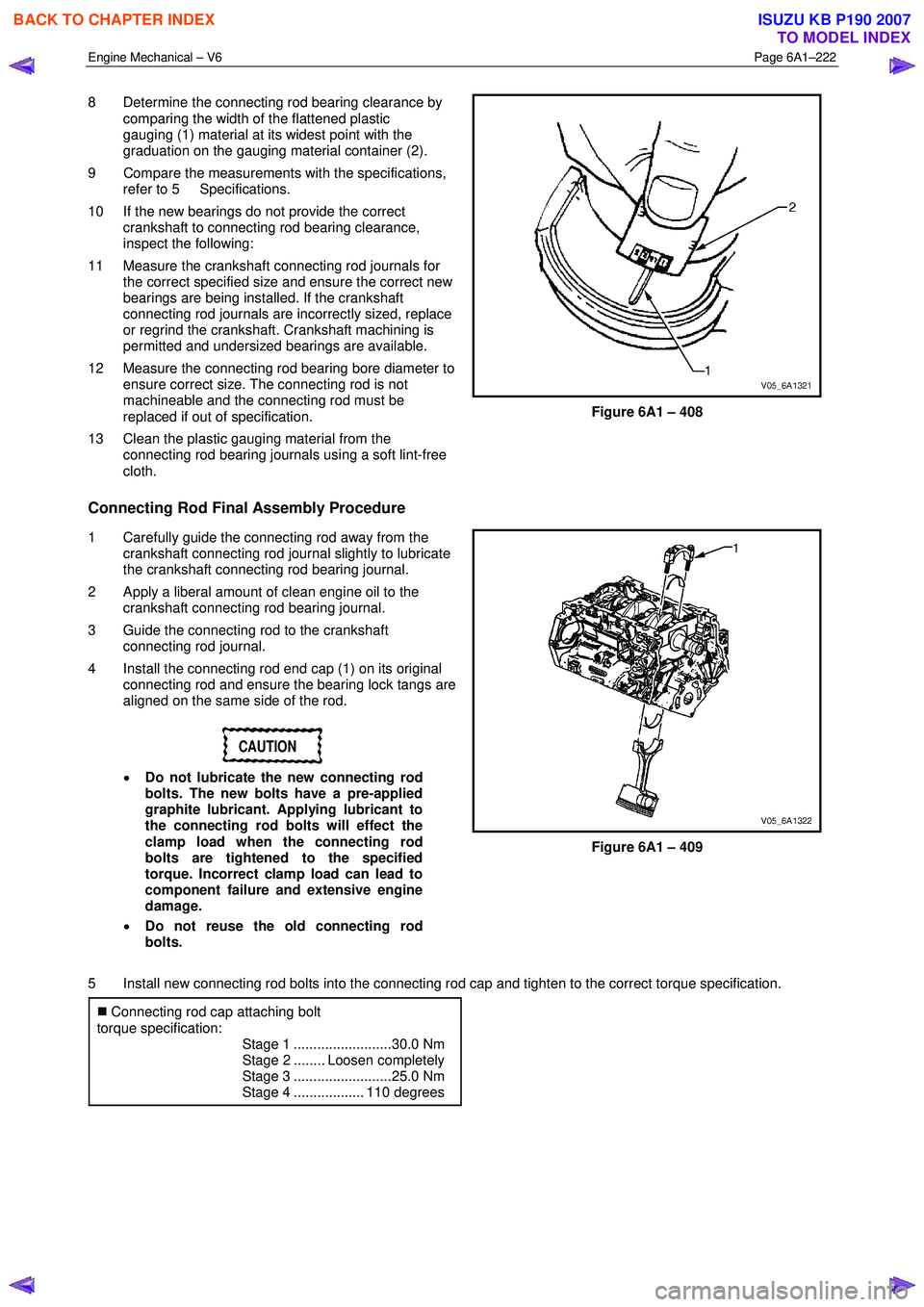
8 Determine the connecting rod bearing clearance by
comparing the width of the flattened plastic
gauging (1) material at its widest point with the
graduation on the gauging material container (2).
9 Compare the measurements with the specifications, refer to 5 Specifications.
10 If the new bearings do not provide the correct crankshaft to connecting rod bearing clearance,
inspect the following:
11 Measure the crankshaft connecting rod journals for the correct specified size and ensure the correct new
bearings are being installed. If the crankshaft
connecting rod journals are incorrectly sized, replace
or regrind the crankshaft. Crankshaft machining is
permitted and undersized bearings are available.
12 Measure the connecting rod bearing bore diameter to ensure correct size. The connecting rod is not
machineable and the connecting rod must be
replaced if out of specification.
13 Clean the plastic gauging material from the connecting rod bearing journals using a soft lint-free
cloth.
Figure 6A1 – 408
Connecting Rod Final Assembly Procedure
1 Carefully guide the connecting rod away from the crankshaft connecting rod journal slightly to lubricate
the crankshaft connecting rod bearing journal.
2 Apply a liberal amount of clean engine oil to the crankshaft connecting rod bearing journal.
3 Guide the connecting rod to the crankshaft connecting rod journal.
4 Install the connecting rod end cap (1) on its original connecting rod and ensure the bearing lock tangs are
aligned on the same side of the rod.
CAUTION
• Do not lubricate the new connecting rod
bolts. The new bolts have a pre-applied
graphite lubricant. Applying lubricant to
the connecting rod bolts will effect the
clamp load when the connecting rod
bolts are tightened to the specified
torque. Incorrect clamp load can lead to
component failure and extensive engine
damage.
• Do not reuse the old connecting rod
bolts.
Figure 6A1 – 409
5 Install new connecting rod bolts into the connecting rod cap and tighten to the correct torque specification. �„ Connecting rod cap attaching bolt
torque specification:
Stage 1 .........................30.0 Nm
Stage 2 ........ Loosen completely
Stage 3 .........................25.0 Nm
Stage 4 .................. 110 degrees
BACK TO CHAPTER INDEX
TO MODEL INDEX
ISUZU KB P190 2007
Page 2702 of 6020
Engine Mechanical – V6 Page 6A1–223
NOTE
During and after installation, ensure each piston
is positioned correctly in the correct cylinder. The
locating arrow on the top of each piston must be
pointing toward the front of the engine.
6 Repeat these procedures for the remaining piston/connecting rod assemblies.
7 Reinstall the oil pan and oil pump pick up assembly, refer to 4.2 Oil Pan and Oil Pump Suction Pipe Assembly.
8 Reinstall the cylinder heads, refer to 3.22 Cylinder Head Assembly.
9 Reinstall the engine assembly, refer to 4.1 Engine .
4.6 Crankshaft and Main Bearings
1 Remove the engine assembly, refer to 4.1 Engine .
2 Remove both cylinder head assemblies, refer to 3.22 Cylinder Head Assembly.
3 Remove the oil pan assembly, refer to 4.2 Oil Pan and Oil Pump Suction Pipe Assembly.
4 Remove the piston and connecting rod assemblies, refer to 4.5 Pistons, Pins, Rings, Connecting Rods and Big- end Bearings.
5 Remove the oil pump assembly, refer to 3.17 Oil Pump Assembly.
6 Remove the crankshaft rear oil seal and plate assembly, refer to 4.4 Crankshaft Rear Seal and Plate Assembly.
7 Remove the crankshaft position sensor, refer to 6C1-3 Engine Management – V6 – Service Operations.
Crankshaft End Play Measurement
1 Place a dial indicator at the end of the crankshaft nose.
2 Gently force the crankshaft towards the front and rear of the cylinder block with a lever while monitoring the movement of the dial indicator.
3 The crankshaft endplay should not exceed specifications, refer to 5 Specifications.
4 If the specifications are exceeded, inspect the thrust bearing thrust outer diameter and the crankshaft thrust wall for wear and/or excessive runout. Compare the values with the specifications, refer to 5 Specifications.
5 Replace the thrust bearing or crankshaft as required.
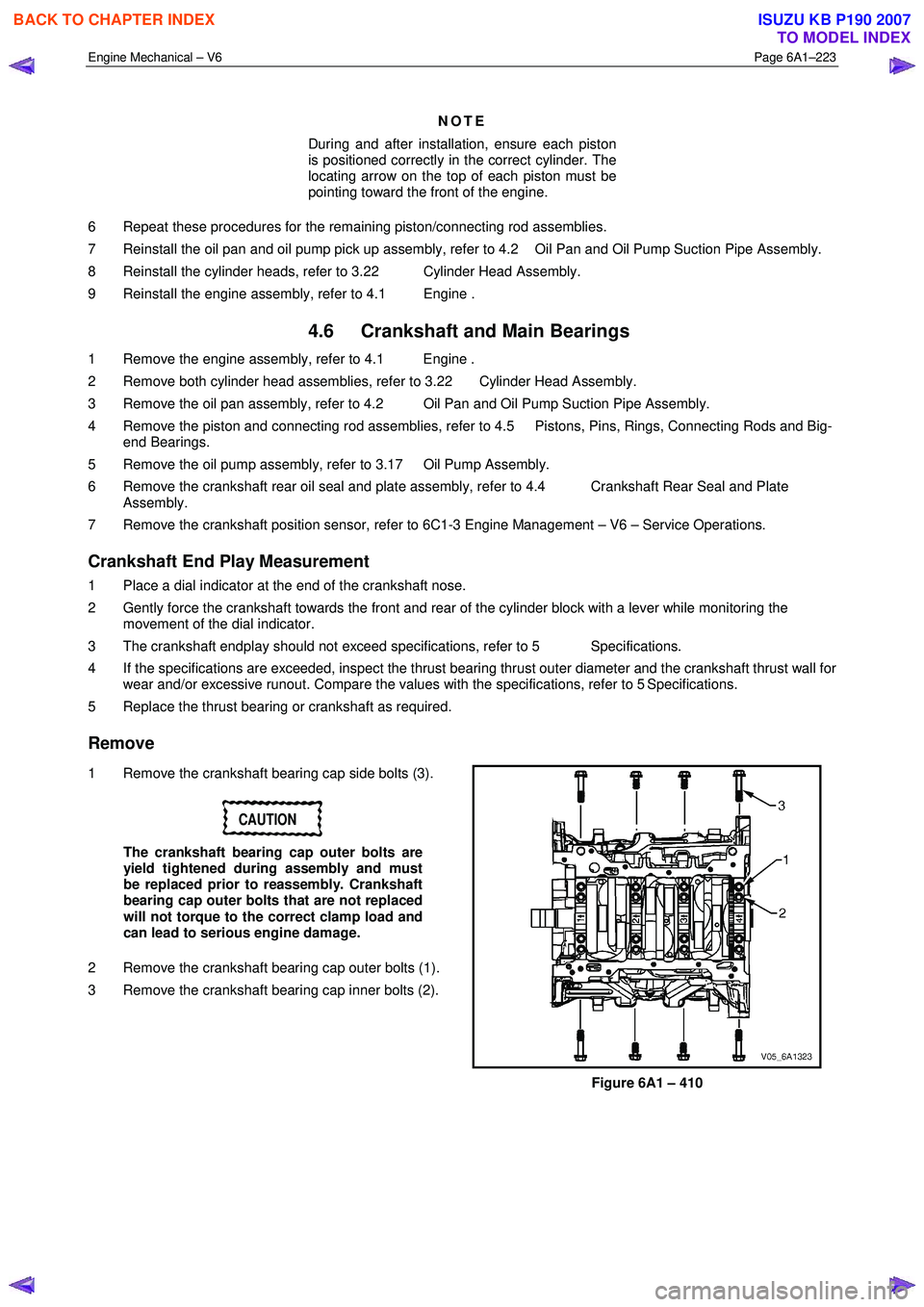
Remove
1 Remove the crankshaft bearing cap side bolts (3).
CAUTION
The crankshaft bearing cap outer bolts are
yield tightened during assembly and must
be replaced prior to reassembly. Crankshaft
bearing cap outer bolts that are not replaced
will not torque to the correct clamp load and
can lead to serious engine damage.
2 Remove the crankshaft bearing cap outer bolts (1).
3 Remove the crankshaft bearing cap inner bolts (2).
Figure 6A1 – 410
BACK TO CHAPTER INDEX
TO MODEL INDEX
ISUZU KB P190 2007