instrument cluster ISUZU KB P190 2007 Workshop Repair Manual
[x] Cancel search | Manufacturer: ISUZU, Model Year: 2007, Model line: KB P190, Model: ISUZU KB P190 2007Pages: 6020, PDF Size: 70.23 MB
Page 109 of 6020
HEATER AND AIR CONDITIONING 1-75
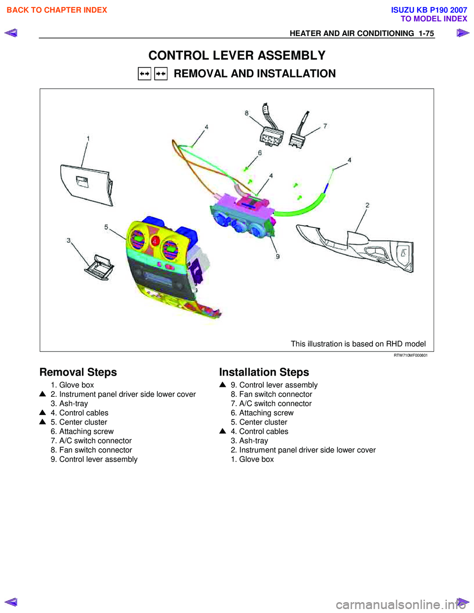
CONTROL LEVER ASSEMBLY
REMOVAL AND INSTALLATION
This illustration is based on RHD model
RTW 710MF000801
Removal Steps
1. Glove box
2. Instrument panel driver side lower cover
3. Ash-tray
4. Control cables
5. Center cluster
6. Attaching screw
7. A/C switch connector
8. Fan switch connector
9. Control lever assembly
Installation Steps
9. Control lever assembly
8. Fan switch connector
7. A/C switch connector
6. Attaching screw
5. Center cluster
4. Control cables
3. Ash-tray
2. Instrument panel driver side lower cover
1. Glove box
BACK TO CHAPTER INDEX
TO MODEL INDEX
ISUZU KB P190 2007
Page 110 of 6020
1-76 HEATER AND AIR CONDITIONING
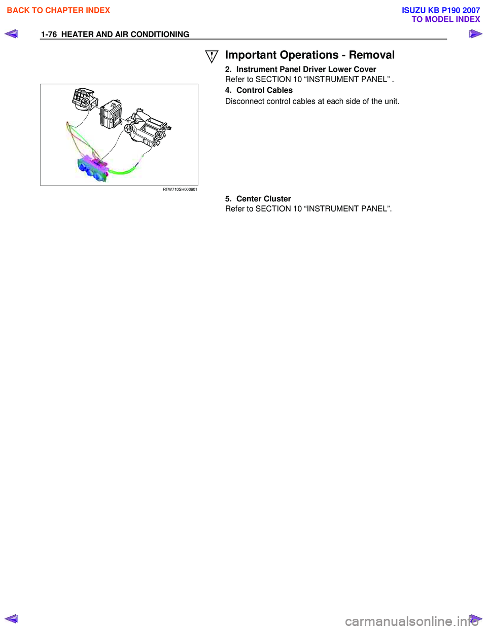
Important Operations - Removal
2. Instrument Panel Driver Lower Cover
Refer to SECTION 10 “INSTRUMENT PANEL” .
RTW 710SH000601
4. Control Cables
Disconnect control cables at each side of the unit.
5. Center Cluster
Refer to SECTION 10 “INSTRUMENT PANEL”.
BACK TO CHAPTER INDEX
TO MODEL INDEX
ISUZU KB P190 2007
Page 639 of 6020
5A-46 BRAKE CONTROL SYSTEM
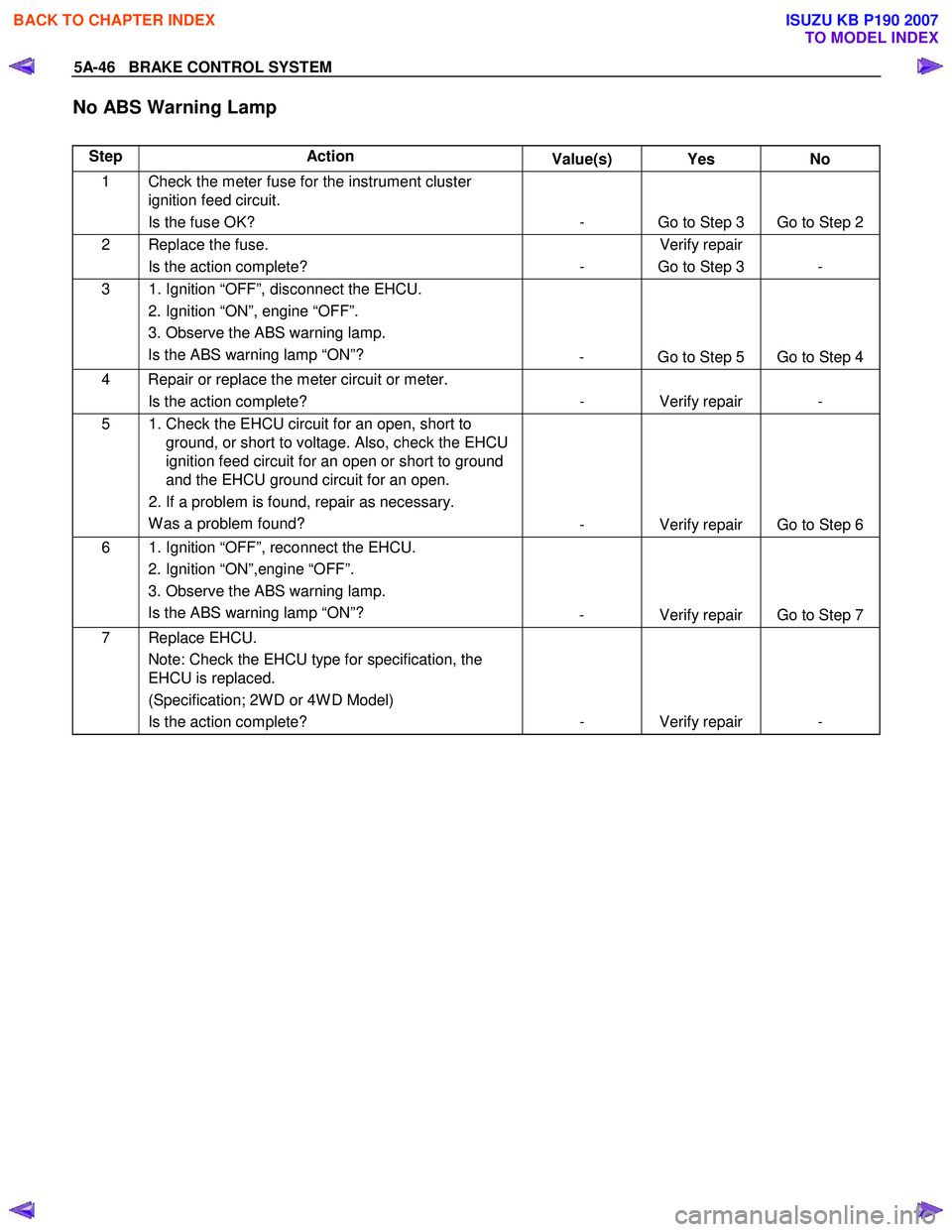
No ABS Warning Lamp
Step Action Value(s) Yes No
1 Check the meter fuse for the instrument cluster
ignition feed circuit.
Is the fuse OK? - Go to Step 3 Go to Step 2
2 Replace the fuse. Is the action complete? - Verify repair
Go to Step 3 -
3 1. Ignition “OFF”, disconnect the EHCU. 2. Ignition “ON”, engine “OFF”.
3. Observe the ABS warning lamp. Is the ABS warning lamp “ON”? - Go to Step 5 Go to Step 4
4 Repair or replace the meter circuit or meter.
Is the action complete? - Verify repair -
5 1. Check the EHCU circuit for an open, short to
ground, or short to voltage. Also, check the EHCU
ignition feed circuit for an open or short to ground
and the EHCU ground circuit for an open.
2. If a problem is found, repair as necessary. W as a problem found? - Verify repair Go to Step 6
6 1. Ignition “OFF”, reconnect the EHCU.
2. Ignition “ON”,engine “OFF”.
3. Observe the ABS warning lamp. Is the ABS warning lamp “ON”? - Verify repair Go to Step 7
7 Replace EHCU.
Note: Check the EHCU type for specification, the
EHCU is replaced.
(Specification; 2W D or 4W D Model)
Is the action complete? - Verify repair -
BACK TO CHAPTER INDEX
TO MODEL INDEX
ISUZU KB P190 2007
Page 772 of 6020
5D-2 PARKING BRAKE SYSTEM
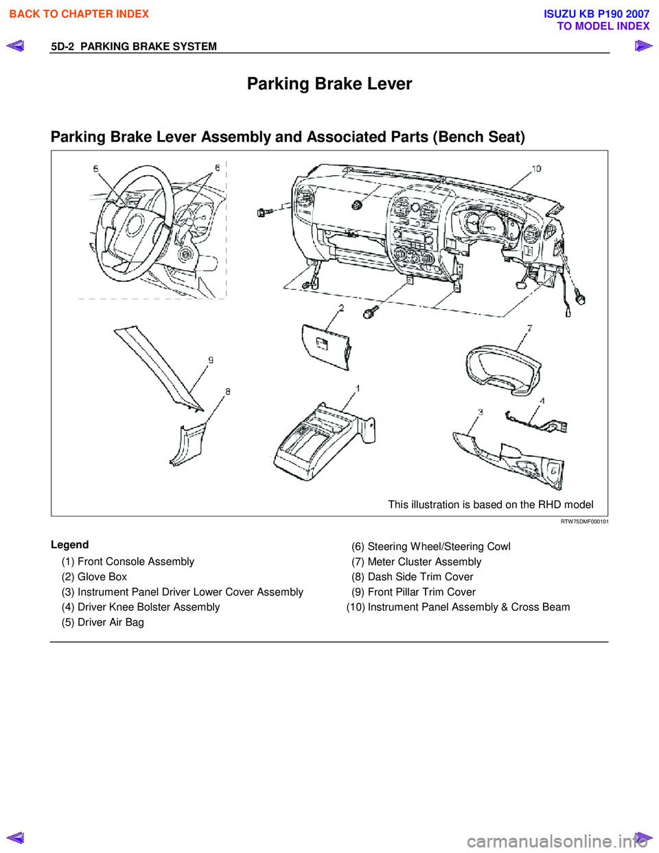
Parking Brake Lever
Parking Brake Lever Assembly and Associated Parts (Bench Seat)
This illustration is based on the RHD model
RTW 75DMF000101
Legend
(1) Front Console Assembly
(2) Glove Box
(3) Instrument Panel Driver Lower Cover Assembly
(4) Driver Knee Bolster Assembly
(5) Driver Air Bag
(6) Steering W heel/Steering Cowl
(7) Meter Cluster Assembly
(8) Dash Side Trim Cover
(9) Front Pillar Trim Cover
(10) Instrument Panel Assembly & Cross Beam
BACK TO CHAPTER INDEX
TO MODEL INDEX
ISUZU KB P190 2007
Page 1090 of 6020
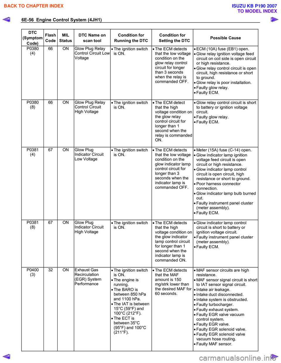
6E-56 Engine Control System (4JH1)
DTC
(Symptom Code) Flash
Code MIL
Status DTC Name on
scan tool Condition for
Running the DTC Condition for
Setting the DTC Possible Cause
P0380
(4) 66 ON Glow Plug Relay
Control Circuit Low
Voltage •
The ignition switch
is ON. •
The ECM detects
that the low voltage
condition on the
glow relay control
circuit for longer
than 3 seconds
when the relay is
commanded OFF.
•
ECM (10A) fuse (EB1) open.
• Glow relay ignition voltage feed
circuit on coil side is open circuit
or high resistance.
• Glow relay control circuit is open
circuit, high resistance or short
to ground.
• Glow relay is poor installation.
• Faulty glow relay.
• Faulty ECM.
P0380 (8) 66 ON
Glow Plug Relay
Control Circuit
High Voltage •
The ignition switch
is ON. •
The ECM detect
that the high
voltage condition on
the glow relay
control circuit for
longer than 1
second when the
relay is commanded
ON.
•
Glow relay control circuit is short
to battery or ignition voltage
circuit.
• Faulty glow relay.
• Faulty ECM.
P0381 (4) 67 ON Glow Plug
Indicator Circuit
Low Voltage •
The ignition switch
is ON.
•
The ECM detects
that the low voltage
condition on the
glow indicator lamp
control circuit for
longer than 3
seconds when the
indicator lamp is
commanded OFF.
•
Meter (15A) fuse (C-14) open.
• Glow indicator lamp ignition
voltage feed circuit is open
circuit or high resistance.
• Glow indicator lamp control
circuit is open circuit, high
resistance or short to ground.
• Poor harness connector
connection.
• Glow indicator lamp bulb burned
out.
• Faulty instrument panel cluster
(meter assembly).
• Faulty ECM.
P0381 (8) 67 ON Glow Plug
Indicator Circuit
High Voltage •
The ignition switch
is ON. •
The ECM detects
that the high
voltage condition on
the glow indicator
lamp control circuit
for longer than 1
second when the
indicator lamp is
commanded ON.
•
Glow indicator lamp control
circuit is short to battery or
ignition voltage circuit.
• Faulty instrument panel cluster
(meter assembly).
• Faulty ECM.
P0400 (3) 32 ON Exhaust Gas
Recirculation
(EGR) System
Performance •
The ignition switch
is ON.
• The engine is
running.
• The BARO is
between 850 hPa
and 1100 hPa.
• The IAT is between
15°C (59°F) and
100°C (212°F).
• The ECT is
between 35°C
(95°F) and 100°C
(211°F).
•
The ECM detects
that the MAF
amount is 150
mg/strk lower than
the desired MAF for
60 seconds.
•
MAF sensor circuits are high
resistance.
• MAF sensor signal circuit is short
to IAT sensor signal circuit.
• Intake air leakage.
• Intake duct disconnected.
• Intake system is obstructed.
• Faulty turbocharger.
• Faulty exhaust system.
• Faulty EGR valve vacuum
control system.
• Faulty EGR valve.
• Faulty EGR solenoid valve.
• Faulty EGR solenoid valve
vacuum hose routing.
• Faulty MAF sensor.
BACK TO CHAPTER INDEX
TO MODEL INDEX
ISUZU KB P190 2007
Page 1092 of 6020
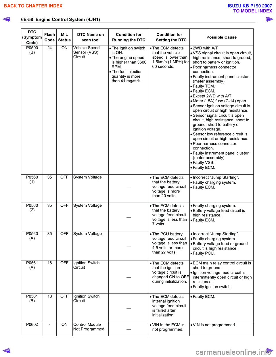
6E-58 Engine Control System (4JH1)
DTC
(Symptom Code) Flash
Code MIL
Status DTC Name on
scan tool Condition for
Running the DTC Condition for
Setting the DTC Possible Cause
P0500
(B) 24 ON Vehicle Speed
Sensor (VSS)
Circuit
•
The ignition switch
is ON.
• The engine speed
is higher than 3600
RPM.
• The fuel injection
quantity is more
than 41 mg/strk.
•
The ECM detects
that the vehicle
speed is lower than
1.5km/h (1 MPH) for
60 seconds.
•
2W D with A/T
• VSS signal circuit is open circuit,
high resistance, short to ground,
short to battery or ignition.
• Poor harness connector
connection.
• Faulty instrument panel cluster
(meter assembly).
• Faulty TCM.
• Faulty ECM.
• Except 2W D with A/T
• Meter (15A) fuse (C-14) open.
• Sensor ignition voltage circuit is
open circuit or high resistance.
• Sensor signal circuit is open
circuit, high resistance, short to
ground, short to battery or
ignition voltage.
• Sensor low reference circuit is
open circuit or high resistance.
• Poor harness connector
connection.
• Faulty instrument panel cluster
(meter assembly).
• Faulty VSS.
• Faulty ECM.
P0560 (1) 35 OFF System Voltage
•
The ECM detects
that the battery
voltage feed circuit
voltage is more
than 20 volts.
•
Incorrect “Jump Starting”.
• Faulty charging system.
• Faulty ECM.
P0560 (2) 35 OFF System Voltage
•
The ECM detects
that the battery
voltage feed circuit
voltage is less than
7 volts.
•
Faulty charging system.
• Battery voltage feed circuit is
high resistance.
• Faulty ECM.
P0560 (A) 35 OFF System Voltage
•
The PCU battery
voltage feed circuit
voltage is less than
4.5 volts or more
than 27 volts.
•
Incorrect “Jump Starting”.
• Faulty charging system.
• Battery voltage feed or ground
circuit is high resistance.
• Faulty PCU.
P0561 (A) 18 OFF Ignition Switch
Circuit
•
The ECM detects
that the ignition
voltage circuit is
changed ON to OFF
during initialization.
•
ECM main relay control circuit is
short to ground.
• Ignition voltage feed circuit is
intermittently open circuit or high
resistance.
• Faulty ignition switch.
P0561 (B) 18 OFF Ignition Switch
Circuit
•
The ECM detects
internal ignition
voltage feed circuit
is failed after
initialization.
•
Faulty ECM.
P0602 - ON Control Module
Not Programmed
•
VIN in the ECM is
not programmed. •
VIN is not programmed.
BACK TO CHAPTER INDEX
TO MODEL INDEX
ISUZU KB P190 2007
Page 1099 of 6020
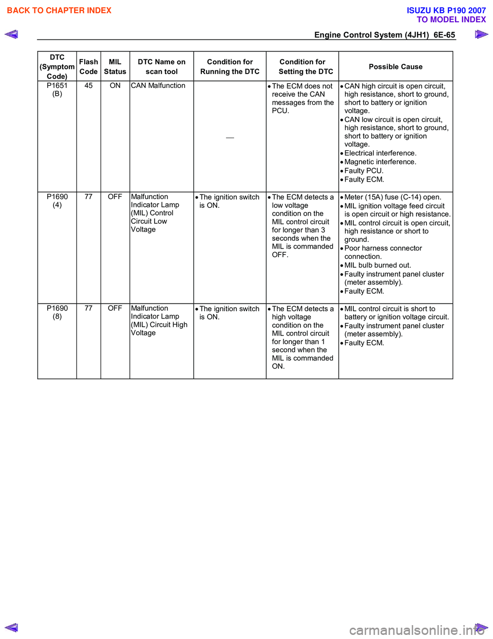
Engine Control System (4JH1) 6E-65
DTC
(Symptom Code) Flash
Code MIL
Status DTC Name on
scan tool Condition for
Running the DTC Condition for
Setting the DTC Possible Cause
P1651
(B) 45 ON CAN Malfunction
•
The ECM does not
receive the CAN
messages from the
PCU.
•
CAN high circuit is open circuit,
high resistance, short to ground,
short to battery or ignition
voltage.
• CAN low circuit is open circuit,
high resistance, short to ground,
short to battery or ignition
voltage.
• Electrical interference.
• Magnetic interference.
• Faulty PCU.
• Faulty ECM.
P1690 (4) 77 OFF Malfunction
Indicator Lamp
(MIL) Control
Circuit Low
Voltage •
The ignition switch
is ON. •
The ECM detects a
low voltage
condition on the
MIL control circuit
for longer than 3
seconds when the
MIL is commanded
OFF.
•
Meter (15A) fuse (C-14) open.
• MIL ignition voltage feed circuit
is open circuit or high resistance.
• MIL control circuit is open circuit,
high resistance or short to
ground.
• Poor harness connector
connection.
• MIL bulb burned out.
• Faulty instrument panel cluster
(meter assembly).
• Faulty ECM.
P1690 (8) 77 OFF Malfunction
Indicator Lamp
(MIL) Circuit High
Voltage •
The ignition switch
is ON. •
The ECM detects a
high voltage
condition on the
MIL control circuit
for longer than 1
second when the
MIL is commanded
ON.
•
MIL control circuit is short to
battery or ignition voltage circuit.
• Faulty instrument panel cluster
(meter assembly).
• Faulty ECM.
BACK TO CHAPTER INDEX
TO MODEL INDEX
ISUZU KB P190 2007
Page 1175 of 6020
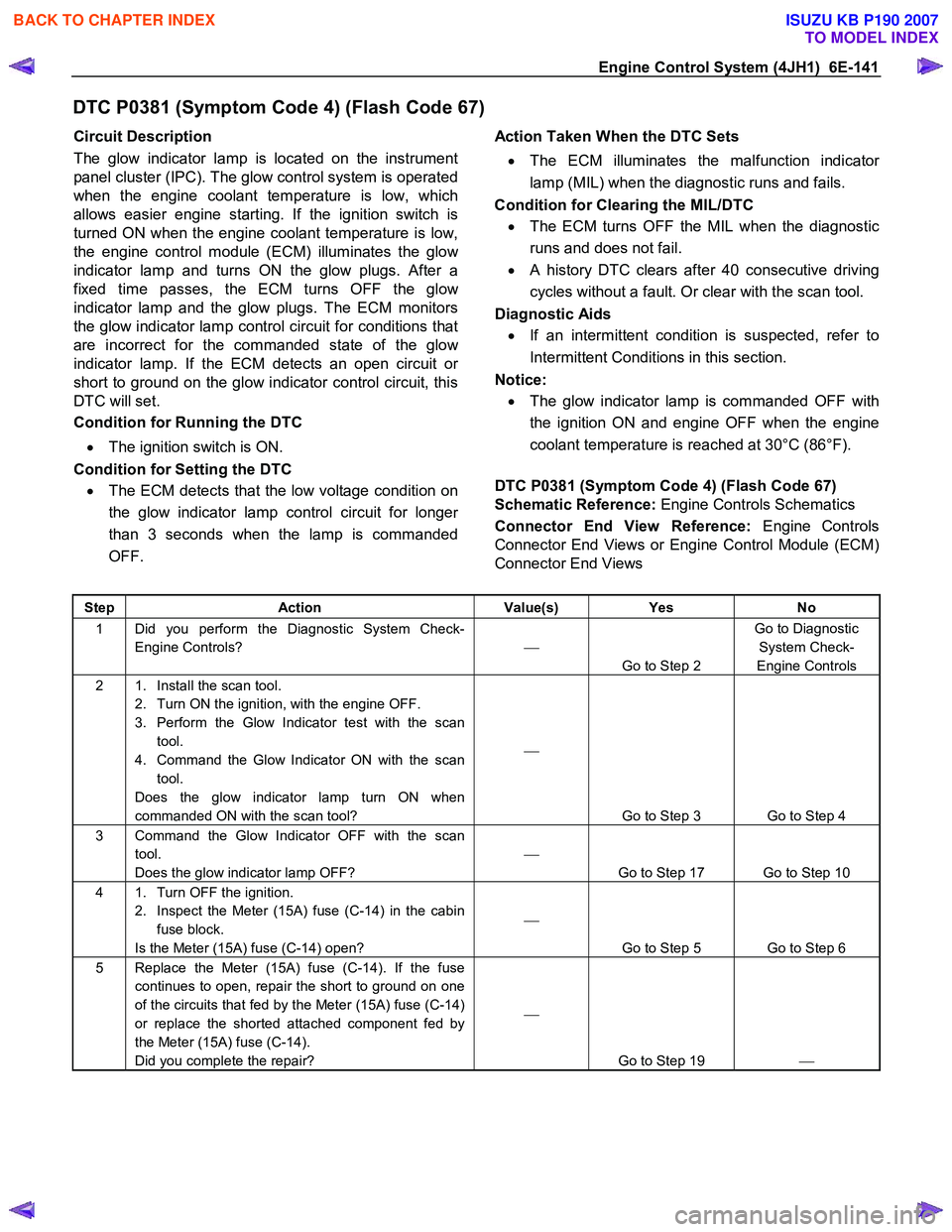
Engine Control System (4JH1) 6E-141
DTC P0381 (Symptom Code 4) (Flash Code 67)
Circuit Description
The glow indicator lamp is located on the instrument
panel cluster (IPC). The glow control system is operated
when the engine coolant temperature is low, which
allows easier engine starting. If the ignition switch is
turned ON when the engine coolant temperature is low,
the engine control module (ECM) illuminates the glo
w
indicator lamp and turns ON the glow plugs. After a
fixed time passes, the ECM turns OFF the glo
w
indicator lamp and the glow plugs. The ECM monitors
the glow indicator lamp control circuit for conditions that
are incorrect for the commanded state of the glo
w
indicator lamp. If the ECM detects an open circuit or
short to ground on the glow indicator control circuit, this
DTC will set.
Condition for Running the DTC
• The ignition switch is ON.
Condition for Setting the DTC • The ECM detects that the low voltage condition on
the glow indicator lamp control circuit for longe
r
than 3 seconds when the lamp is commanded
OFF.
Action Taken When the DTC Sets
• The ECM illuminates the malfunction indicato
r
lamp (MIL) when the diagnostic runs and fails.
Condition for Clearing the MIL/DTC
• The ECM turns OFF the MIL when the diagnostic
runs and does not fail.
• A history DTC clears after 40 consecutive driving
cycles without a fault. Or clear with the scan tool.
Diagnostic Aids
• If an intermittent condition is suspected, refer to
Intermittent Conditions in this section.
Notice:
• The glow indicator lamp is commanded OFF with
the ignition ON and engine OFF when the engine
coolant temperature is reached at 30°C (86°F).
DTC P0381 (Symptom Code 4) (Flash Code 67)
Schematic Reference: Engine Controls Schematics
Connector End View Reference: Engine Controls
Connector End Views or Engine Control Module (ECM)
Connector End Views
Step Action Value(s) Yes No
1 Did you perform the Diagnostic System Check-
Engine Controls?
Go to Step 2 Go to Diagnostic
System Check-
Engine Controls
2 1. Install the scan tool. 2. Turn ON the ignition, with the engine OFF.
3. Perform the Glow Indicator test with the scan tool.
4. Command the Glow Indicator ON with the scan tool.
Does the glow indicator lamp turn ON when
commanded ON with the scan tool?
Go to Step 3 Go to Step 4
3 Command the Glow Indicator OFF with the scan tool.
Does the glow indicator lamp OFF?
Go to Step 17 Go to Step 10
4 1. Turn OFF the ignition. 2. Inspect the Meter (15A) fuse (C-14) in the cabin fuse block.
Is the Meter (15A) fuse (C-14) open?
Go to Step 5 Go to Step 6
5 Replace the Meter (15A) fuse (C-14). If the fuse continues to open, repair the short to ground on one
of the circuits that fed by the Meter (15A) fuse (C-14)
or replace the shorted attached component fed by
the Meter (15A) fuse (C-14).
Did you complete the repair?
Go to Step 19
BACK TO CHAPTER INDEX
TO MODEL INDEX
ISUZU KB P190 2007
Page 1176 of 6020
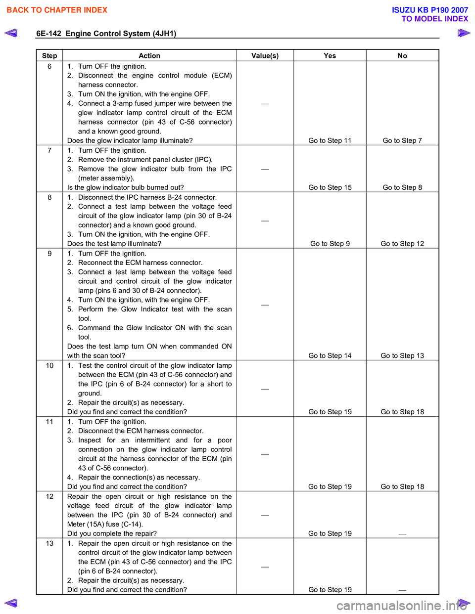
6E-142 Engine Control System (4JH1)
Step Action Value(s) Yes No
6 1. Turn OFF the ignition.
2. Disconnect the engine control module (ECM) harness connector.
3. Turn ON the ignition, with the engine OFF.
4. Connect a 3-amp fused jumper wire between the glow indicator lamp control circuit of the ECM
harness connector (pin 43 of C-56 connector)
and a known good ground.
Does the glow indicator lamp illuminate?
Go to Step 11 Go to Step 7
7 1. Turn OFF the ignition. 2. Remove the instrument panel cluster (IPC).
3. Remove the glow indicator bulb from the IPC (meter assembly).
Is the glow indicator bulb burned out?
Go to Step 15 Go to Step 8
8 1. Disconnect the IPC harness B-24 connector. 2. Connect a test lamp between the voltage feed circuit of the glow indicator lamp (pin 30 of B-24
connector) and a known good ground.
3. Turn ON the ignition, with the engine OFF.
Does the test lamp illuminate?
Go to Step 9 Go to Step 12
9 1. Turn OFF the ignition. 2. Reconnect the ECM harness connector.
3. Connect a test lamp between the voltage feed circuit and control circuit of the glow indicator
lamp (pins 6 and 30 of B-24 connector).
4. Turn ON the ignition, with the engine OFF.
5. Perform the Glow Indicator test with the scan tool.
6. Command the Glow Indicator ON with the scan tool.
Does the test lamp turn ON when commanded ON
with the scan tool?
Go to Step 14 Go to Step 13
10 1. Test the control circuit of the glow indicator lamp between the ECM (pin 43 of C-56 connector) and
the IPC (pin 6 of B-24 connector) for a short to
ground.
2. Repair the circuit(s) as necessary.
Did you find and correct the condition?
Go to Step 19 Go to Step 18
11 1. Turn OFF the ignition. 2. Disconnect the ECM harness connector.
3. Inspect for an intermittent and for a poor connection on the glow indicator lamp control
circuit at the harness connector of the ECM (pin
43 of C-56 connector).
4. Repair the connection(s) as necessary.
Did you find and correct the condition?
Go to Step 19 Go to Step 18
12 Repair the open circuit or high resistance on the voltage feed circuit of the glow indicator lamp
between the IPC (pin 30 of B-24 connector) and
Meter (15A) fuse (C-14).
Did you complete the repair?
Go to Step 19
13 1. Repair the open circuit or high resistance on the
control circuit of the glow indicator lamp between
the ECM (pin 43 of C-56 connector) and the IPC
(pin 6 of B-24 connector).
2. Repair the circuit(s) as necessary.
Did you find and correct the condition?
Go to Step 19
BACK TO CHAPTER INDEX
TO MODEL INDEX
ISUZU KB P190 2007
Page 1178 of 6020
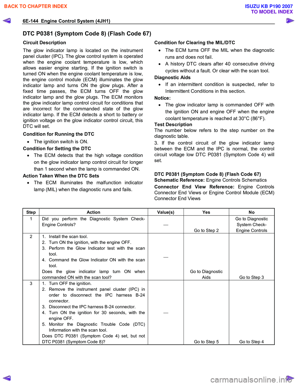
6E-144 Engine Control System (4JH1)
DTC P0381 (Symptom Code 8) (Flash Code 67)
Circuit Description
The glow indicator lamp is located on the instrument
panel cluster (IPC). The glow control system is operated
when the engine coolant temperature is low, which
allows easier engine starting. If the ignition switch is
turned ON when the engine coolant temperature is low,
the engine control module (ECM) illuminates the glo
w
indicator lamp and turns ON the glow plugs. After a
fixed time passes, the ECM turns OFF the glo
w
indicator lamp and the glow plugs. The ECM monitors
the glow indicator lamp control circuit for conditions that
are incorrect for the commanded state of the glo
w
indicator lamp. If the ECM detects a short to battery or
ignition voltage on the glow indicator control circuit, this
DTC will set.
Condition for Running the DTC • The ignition switch is ON.
Condition for Setting the DTC
• The ECM detects that the high voltage condition
on the glow indicator lamp control circuit for longe
r
than 1 second when the lamp is commanded ON.
Action Taken When the DTC Sets
• The ECM illuminates the malfunction indicato
r
lamp (MIL) when the diagnostic runs and fails.
Condition for Clearing the MIL/DTC
• The ECM turns OFF the MIL when the diagnostic
runs and does not fail.
• A history DTC clears after 40 consecutive driving
cycles without a fault. Or clear with the scan tool.
Diagnostic Aids
• If an intermittent condition is suspected, refer to
Intermittent Conditions in this section.
Notice:
• The glow indicator lamp is commanded OFF with
the ignition ON and engine OFF when the engine
coolant temperature is reached at 30°C (86°F).
Test Description
The number below refers to the step number on the
diagnostic table.
3. If the control circuit of the glow indicator lamp
between the ECM and the IPC is normal, the control
circuit voltage low DTC P0381 (Symptom Code 4) will
set.
DTC P0381 (Symptom Code 8) (Flash Code 67)
Schematic Reference: Engine Controls Schematics
Connector End View Reference: Engine Controls
Connector End Views or Engine Control Module (ECM)
Connector End Views
Step Action Value(s) Yes No
1 Did you perform the Diagnostic System Check-
Engine Controls?
Go to Step 2 Go to Diagnostic
System Check-
Engine Controls
2 1. Install the scan tool. 2. Turn ON the ignition, with the engine OFF.
3. Perform the Glow Indicator test with the scan tool.
4. Command the Glow Indicator ON with the scan tool.
Does the glow indicator lamp turn ON when
commanded ON with the scan tool?
Go to Diagnostic Aids Go to Step 3
3 1. Turn OFF the ignition. 2. Remove the instrument panel cluster (IPC) in order to disconnect the IPC harness B-24
connector.
3. Disconnect the IPC harness B-24 connector.
4. Turn ON the ignition for 30 seconds, with the engine OFF.
5. Monitor the Diagnostic Trouble Code (DTC) Information with the scan tool.
Does DTC P0381 (Symptom Code 4) set, but not
DTC P0381 (Symptom Code 8)?
Go to Step 5 Go to Step 4
BACK TO CHAPTER INDEX
TO MODEL INDEX
ISUZU KB P190 2007