lock ISUZU KB P190 2007 Workshop Service Manual
[x] Cancel search | Manufacturer: ISUZU, Model Year: 2007, Model line: KB P190, Model: ISUZU KB P190 2007Pages: 6020, PDF Size: 70.23 MB
Page 351 of 6020

3C-30 FRONT SUSPENSION
Service Precaution
WARNING: THIS VEHICLE HAS A SUPPLEMENTAL
RESTRAINT SYSTEM (SRS). REFER TO THE SRS
COMPONENT AND WIRING LOCATION VIEW IN
ORDER TO DETERMINE WHETHER YOU ARE
PERFORMING SERVICE ON OR NEAR THE SRS
COMPONENTS OR THE SRS WIRING. WHEN YOU
ARE PERFORMING SERVICE ON OR NEAR THE
SRS COMPONENTS OR THE SRS WIRING, REFER
TO THE SRS SERVICE INFORMATION. FAILURE TO
FOLLOW WARNINGS COULD RESULT IN
POSSIBLE AIR BAG DEPLOYMENT, PERSONAL
INJURY, OR OTHERWISE UNNECESSARY SRS
SYSTEM REPAIRS.
CAUTION: Always use the correct fastener in the
proper location. When you replace a fastener, use
ONLY the exact part number for that application.
ISUZU/GM will call out those fasteners that require
a replacement after removal. ISUZU/GM will also
call out the fasteners that require thread lockers o
r
thread sealant. UNLESS OTHERWISE SPECIFIED,
do not use supplemental coatings (paints, greases,
or other corrosion inhibitors) on threaded fasteners
or fastener joint interfaces. Generally, such
coatings adversely affect the fastener torque and
the joint clamping force, and may damage the
fastener. When you install fasteners, use the
correct tightening sequence and specifications.
Following these instructions can help you avoid
damage to parts and systems.
BACK TO CHAPTER INDEX
TO MODEL INDEX
ISUZU KB P190 2007
Page 418 of 6020

4A-2 PROPELLER SHAFT
Service Precaution
WARNING: THIS VEHICLE HAS A
SUPPLEMENTAL RESTRAINT SYSTEM (SRS).
REFER TO THE SRS COMPONENT AND WIRING
LOCATION VIEW IN ORDER TO DETERMINE
WHETHER YOU ARE PERFORMING SERVICE ON
OR NEAR THE SRS COMPONENTS OR THE SRS
WIRING. WHEN YOU ARE PERFORMING
SERVICE ON OR NEAR THE SRS COMPONENTS
OR THE SRS WIRING, REFER TO THE SRS
SERVICE INFORMATION. FAILURE TO FOLLOW
WARNING COULD RESULT IN POSSIBLE AIR
BAG DEPLOYMENT, PERSONAL INJURY, OR
OTHERWISE UNNEEDED SRS SYSTEM
REPAIRS.
CAUTION : Always use the correct fastener in the
proper location. When you replace a fastener,
use ONLY the exact part number for that
application. ISUZU/GM will call out those
fasteners that require a replacement afte
r
removal. ISUZU/GM will also call out the
fasteners that require thread lockers or thread
sealant. UNLESS OTHERWISE SPECIFIED, do
not use supplemental coatings (Paints, greases,
or other corrosion inhibitors) on threaded
fasteners or fastener joint interfaces. Generally,
such coatings adversely affect the fastene
r
torque and the joint clamping force, and may
damage the fastener. When you install fasteners,
use the correct tightening sequence and
specifications. Following these instructions can
help you avoid damage to parts and systems.
BACK TO CHAPTER INDEX
TO MODEL INDEX
ISUZU KB P190 2007
Page 434 of 6020

4A-18 PROPELLER SHAFT
Rear Propeller Shaft Assembly
(4×2, 4×4)
RTW 54ALF000101
Legend
1. Splined Yoke
2. Journal Assembly
3. 1st Tube Assembly
4. Center Bearing
5. Plain W asher
6. Center Yoke
7. Lock Nut
8. 2nd Tube Assembly
9. Flange Yoke
10. Snap Ring
BACK TO CHAPTER INDEX
TO MODEL INDEX
ISUZU KB P190 2007
Page 435 of 6020

PROPELLER SHAFT 4A-19
Disassembly
1. Disassembly the three portions of the journal assemblies.
2. Remove the splined yoke, the 1st tube assembly with cente
r
bearing, the 2nd tube assembly and the flange yoke.
3. Remove the lock nut.
4. Remove the center yoke, the plain washer the cente
r
bearing and the 1st tube assembly.
Reassembly
1. Install the center bearing on the 1st tube assembly.
Clean the bearing fitting face.
Repack the grease.
Amount of grease
required g(oz) Approx. 12 (0.42)
2. Install the plain washer and the center yoke.
3. Install the lock nut and tighten it to the specified torque.
Lock nut Torque : 118 N ⋅
⋅⋅
⋅
m (12.0 kgf ⋅
⋅⋅
⋅
m/87lb ⋅
⋅⋅
⋅
ft)
(1) Discard the flange nut and install a new one.
(2) Stake the outer face of the flange nut against the slot in the shaft.
4. Install the splined yoke, the 1st tube assembly with cente
r
bearing, the 2nd tube assembly and the flange yoke by
assembling the universal joint.
BACK TO CHAPTER INDEX
TO MODEL INDEX
ISUZU KB P190 2007
Page 442 of 6020

4A-26 PROPELLER SHAFT
401RS027
Propeller Shaft Run-out
Support the ends of the propeller shaft on V-blocks (2) and
check for run-out by holding the probe of a dial indicator (1) in
contact with the center part of the shaft. If the amount of run-
out is beyond the standard value for assembly, correct with a
bench press or replace the shaft with a new propeller shaft
assembly.
Standard: 0.3 mm (0.012 in)
Limit: 0.5 mm (0.02 in)
401RS009
Play in Splines in Normal Direction of Rotation
Check the amount of play between the sleeve yoke (1) and the
propeller shaft spline (2) in the direction of rotation, using a
pointed feeler gauge.
Standard: 0.073-0.156 mm (0.003-0.006 in)
Limit: 0.3 mm (0.012 in)
401RS010
Play in Universal Joint
Limit: Less than 0.1 mm (0.004 in)
401RS011
Reassembly
1. Install spider to flange yoke. Be sure to install the spider by
aligning the setting marks made during disassembly.
2. Apply a molybdenum-disulfide grease or multi-purpose type grease NLGI No. 2 to inside of the bearing cap.
Grease Amount: Approx. 1.2 g (0.042 oz)
BACK TO CHAPTER INDEX
TO MODEL INDEX
ISUZU KB P190 2007
Page 445 of 6020

REAR AXLE 4B-1
SECTION 4B
REAR AXLE
TABLE OF CONTENTS
PAGE
Main Data and Specifications ........................................................................................... 4B- 3
Torque Specifications .............................................................................................................. 4B- 4
Recommended Liquid Gasket .......................................................................................... 4B- 6
Recommended Thread Locking Agents .......................................................................... 4B- 6
Rear Axle Assembly .......................................................................................................... 4B- 7
General Description...................................................................................................... 4B- 7
Servicing ...................................................................................................................... ...... 4B- 8
Rear Axle ...................................................................................................................... ...... 4B- 9
Disassembly .................................................................................................................. 4B - 10
Inspection and Repair .................................................................................................. 4B- 14
Reassembly ................................................................................................................... 4B - 15
Differential Assembly ..................................................................................................................... 4B- 20
Disassembly .................................................................................................................. 4B - 21
Reassembly ................................................................................................................... 4B - 24
Differential Cage Assembly .......................................................................................................... 4B- 34
Disassembly .................................................................................................................. 4B - 35
Inspection and Repair .............................................................................................................. 4B- 35
Reassembly ................................................................................................................................. 4B- 37
Limited Slip Differential (LSD) .......................................................................................... 4B- 38
Disassembly ............................................................................................................................... .4B- 39
Inspection and Repair .................................................................................................. 4B- 40
Reassembly ................................................................................................................... 4B - 42
Troubleshooting............................................................................................................ 4B- 45
Special Service Tool ................................................................................................................. 4B- 56
BACK TO CHAPTER INDEX
TO MODEL INDEX
ISUZU KB P190 2007
Page 446 of 6020

4B-2 REAR AXLE
Service Precaution
WARNING:
THIS VEHICLE HAS A SUPPLEMENTAL
RESTRAINT SYSTEM (SRS). REFER TO THE SRS
COMPONENT AND WIRING LOCATION VIEW IN
ORDER TO DETERMINE WHETHER YOU ARE
PERFORMING SERVICE ON OR NEAR THE SRS
COMPONENTS OR THE SRS WIRING. WHEN YOU
ARE REFORMING SERVICE ON OR NEAR THE
SRS COMPONENTS OR THE SRS WIRING, REFER
TO THE SRS SERVICE INFORMATION. FAILURE
TO FOLLOW WARNINGS COULD RESULT IN
POSSIBLE AIR BAG DEPLOYMENT, PERSONAL
INJURY, OR OTHERWISE UNNEEDED SRS
SYSTEM REPAIRS.
CAUTION:
Always use the correct fastener in the prope
r
location. When you replace a fastener, use ONLY
the exact part number for that application.
ISUZU/GM will call out those fasteners that require
a replacement after removal. ISUZU/GM will also
call out the fasteners that require thread lockers o
r
thread sealant. UNLESS OTHERWISE SPECIFIED,
do not use supplemental coatings (Paints,
greases, or other corrosion inhibitors) on threaded
fasteners or fastener joint interfaces. Generally,
such coatings adversely affect the fastener torque
and the joint clamping force, and may damage the
fastener. When you install fasteners, use the
correct tightening sequence and specification.
Following these instructions can help you avoid
damage to parts and systems.
BACK TO CHAPTER INDEX
TO MODEL INDEX
ISUZU KB P190 2007
Page 450 of 6020

4B-6 REAR AXLE
RECOMMENDED LIQUID GASKET
Type Brand Name Manufacture Remarks
RTV* Silicon Base ThreeBond 1207B
ThreeBond 1207C
ThreeBond 1215
Three Bond
Three Bond
Three Bond
For Engine Repairs
For Axle Case
Repairs, T/M
W ater Base ThreeBond 1141E Three Bond For Engine Repairs
Solvent ThreeBond 1104
BelcoBond 4
BelcoBond 401
BelcoBond 402 Three bond
Isuzu
Isuzu
Isuzu
For Engine Repairs
Anaerobic LOCTITE 515
LOCTITE 518 Loctite
Loctite All
* RTV : Room Temperature Vulcanizer
Note :
1. It is very important that the liquid gaskets listed above or their exact equivalent be used on the
vehicle.
2. Be careful to use the specified amount of liquid gasket.
Follow the manufacture's instructions at all times.
3. Be absolutely sure to remove all lubricants and
moisture from the connecting surfaces before
applying the liquid gasket.
The connecting surfaces must be perfectly dry.
4. LOCTITE 515 and LOCTITE 518 harden upon contact with a metal surface.
Do not apply LOCTITE 515 or LOCTITE 518 between two metal surfaces having a clearance
of greater than 0.25 mm (0.01 in). Poo
r
adhesion will result.
RECOMMENDED THREAD LOCKING AGENTS
LOCTITE Type LOCTITE Color Application Steps
LOCTITE 242
Blue 1. Completely remove all lubricant and moisture from the bolts and
the female threaded surfaces of the parts to be joined.
The surfaces must be perfectly dry.
LOCTITE 262
Red 2. Apply LOCTITE to the bolts.
LOCTITE 270
Green
LOCTITE 271
Red
3. Tighten the bolts to the specified torque.
4. W ait at least one hour before continuing the installation procedure.
BACK TO CHAPTER INDEX
TO MODEL INDEX
ISUZU KB P190 2007
Page 456 of 6020

4B-12 REAR AXLE
9. Use offset box wrench to compress locking lugs
on the cable, then remove parking brake oute
r
cable from back plate.
311RS012
Legend
1. Offset Box W rench
10. Remove wheel cylinder.
11. Remove bearing holder fixing nuts.
12. Take out axle shaft assembly with back plate and
set it on a bench press as following illustration.
W hen axle shaft is extracted, since axle case oil
seal is damaged, replace the axle case oil seal.
13. Remove snap ring. Use snap ring pliers to
remove. Snap ring is prohibition of reuse.
14. Remove shim (If so equipped)
15. Grind the retainer surfaces using a grinder, then chisel them out with a chisel.
16. Position remover 5-8840-2831-0 on the bearing
holder with 4 nuts.
RTW 54BSH000801
BACK TO CHAPTER INDEX
TO MODEL INDEX
ISUZU KB P190 2007
Page 469 of 6020

REAR AXLE 4B-25
b. Tighten the nut to the specified torque.
Torque:
φ220mm : 2.7 N ⋅m (0.28 kgf ⋅m/24 lb ⋅in)
φ194mm : 2.3 N ⋅m (0.23 kgf ⋅m/20 lb ⋅in)
425RW 030
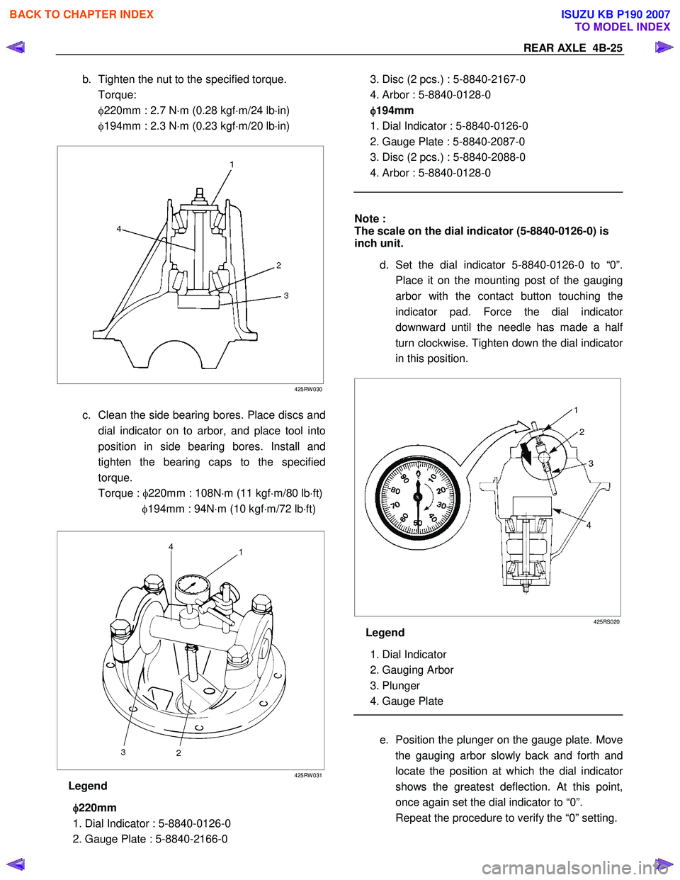
c. Clean the side bearing bores. Place discs and
dial indicator on to arbor, and place tool into
position in side bearing bores. Install and
tighten the bearing caps to the specified
torque.
Torque : φ220mm : 108N ⋅m (11 kgf ⋅m/80 lb ⋅ft)
φ194mm : 94N ⋅m (10 kgf ⋅m/72 lb ⋅ft)
425RW 031
Legend
φ
φφ
φ
220mm
1. Dial Indicator : 5-8840-0126-0
2. Gauge Plate : 5-8840-2166-0
3. Disc (2 pcs.) : 5-8840-2167-0
4. Arbor : 5-8840-0128-0
φ
φφ
φ
194mm
1. Dial Indicator : 5-8840-0126-0
2. Gauge Plate : 5-8840-2087-0
3. Disc (2 pcs.) : 5-8840-2088-0
4. Arbor : 5-8840-0128-0
Note :
The scale on the dial indicator (5-8840-0126-0) is
inch unit.
d. Set the dial indicator 5-8840-0126-0 to “0”.
Place it on the mounting post of the gauging
arbor with the contact button touching the
indicator pad. Force the dial indicato
r
downward until the needle has made a hal
f
turn clockwise. Tighten down the dial indicato
r
in this position.
425RS020
Legend
1. Dial Indicator
2. Gauging Arbor
3. Plunger
4. Gauge Plate
e. Position the plunger on the gauge plate. Move
the gauging arbor slowly back and forth and
locate the position at which the dial indicato
r
shows the greatest deflection. At this point,
once again set the dial indicator to “0”.
Repeat the procedure to verify the “0” setting.
BACK TO CHAPTER INDEX
TO MODEL INDEX
ISUZU KB P190 2007