lock ISUZU KB P190 2007 Workshop Owner's Manual
[x] Cancel search | Manufacturer: ISUZU, Model Year: 2007, Model line: KB P190, Model: ISUZU KB P190 2007Pages: 6020, PDF Size: 70.23 MB
Page 270 of 6020
POWER-ASSISTED STEERING SYSTEM 3B-9
4. Install all the lines and hoses. Fill the system with
new power steering fluid and bleed the system as
described in Bleeding the Power Steering System.
Operate the engine for about 15 minutes.
Remove the pump return line at the pump inlet and
plug the connection on the pump. W hile refilling the
reservoir, check the draining fluid for contamination.
If foreign matter is still evident, replace all lines,
disassemble and clean or replace the powe
r
steering system components. Do not re-use any
drained power steering fluid.
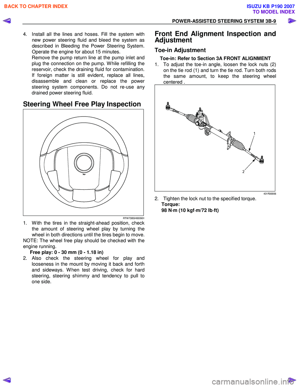
Steering Wheel Free Play Inspection
RTW 73BSH000901
1. W ith the tires in the straight-ahead position, check the amount of steering wheel play by turning the
wheel in both directions until the tires begin to move.
NOTE: The wheel free play should be checked with the
engine running. Free play: 0 - 30 mm (0 - 1.18 in)
2.
Also check the steering wheel for play and
looseness in the mount by moving it back and forth
and sideways. W hen test driving, check for hard
steering, steering shimmy and tendency to pull to
one side.
Front End Alignment Inspection and
Adjustment
Toe-in Adjustment
Toe-in: Refer to Section 3A FRONT ALIGNMENT
1. To adjust the toe-in angle, loosen the lock nuts (2) on the tie rod (1) and turn the tie rod. Turn both rods
the same amount, to keep the steering wheel
centered .
431R30006
2. Tighten the lock nut to the specified torque. Torque:
98 N ⋅
⋅⋅
⋅
m (10 kgf ⋅
⋅⋅
⋅
m/72 lb ⋅
⋅⋅
⋅
ft)
BACK TO CHAPTER INDEX
TO MODEL INDEX
ISUZU KB P190 2007
Page 274 of 6020
POWER-ASSISTED STEERING SYSTEM 3B-13
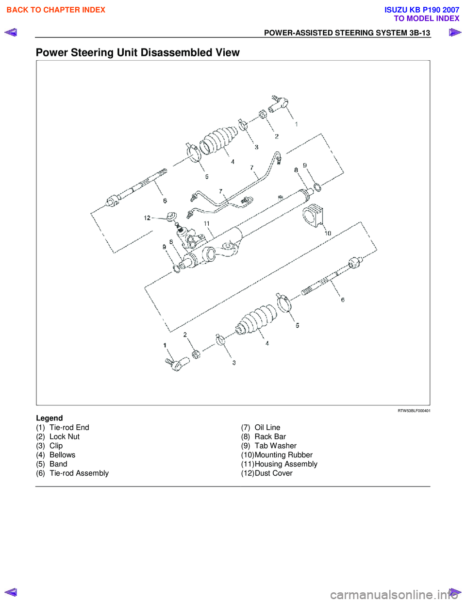
Power Steering Unit Disassembled View
RTW 53BLF000401
Legend
(1) Tie-rod End
(2) Lock Nut
(3) Clip
(4) Bellows
(5) Band
(6) Tie-rod Assembly
(7) Oil Line
(8) Rack Bar
(9) Tab W asher
(10) Mounting Rubber
(11) Housing Assembly
(12) Dust Cover
BACK TO CHAPTER INDEX
TO MODEL INDEX
ISUZU KB P190 2007
Page 275 of 6020
3B-14 POWER-ASSISTED STEERING SYSTEM
Disassembly
NOTE : The valve hosing is made of aluminum and care
should be exercised when clamping in a vise, etc.
to prevent distortion or damage.
For the left side, follow the same steps as right side.
1. Loosen lock nut and remove tie-rod end.
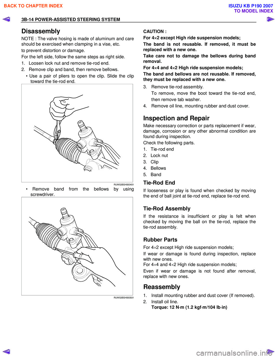
2. Remove clip and band, then remove bellows.
• Use a pair of pliers to open the clip. Slide the cliptoward the tie-rod end.
RUW 53BSH000401
• Remove band from the bellows by using
screwdriver.
RUW 53BSH000501
CAUTION :
For 4 ×
××
×
2 except High ride suspension models;
The band is not reusable. If removed, it must be
replaced with a new one.
Take care not to damage the bellows during band
removal.
For 4 ×
××
×
4 and 4 ×
××
×
2 High ride suspension models;
The band and bellows are not reusable. If removed,
they must be replaced with a new one.
3. Remove tie-rod assembly.
To remove, move the boot toward the tie-rod end, then remove tab washer.
4. Remove oil line, mounting rubber and dust cover.
Inspection and Repair
Make necessary correction or parts replacement if wear,
damage, corrosion or any other abnormal condition are
found during inspection.
Check the following parts.
1. Tie-rod end
2. Lock nut
3. Clip
4. Bellows
5. Band
Tie-Rod End
If looseness or play is found when checked by moving
the end of ball joint at tie-rod end, replace tie-rod end.
Tie-Rod Assembly
If the resistance is insufficient or play is felt when
checked by moving the ball on the tie-rod, replace the
tie-rod assembly.
Rubber Parts
For 4 ×2 except High ride suspension models;
If wear or damage is found during inspection, replace
with new ones.
For 4 ×4 and 4 ×2 High ride suspension models;
Even if wear or damage is not found after removal,
replace with new ones.
Reassembly
1. Install mounting rubber and dust cover (If removed).
2. Install oil line. Torque: 12 N ⋅
⋅⋅
⋅
m (1.2 kgf ⋅
⋅⋅
⋅
m/104 lb ⋅
⋅⋅
⋅
in)
BACK TO CHAPTER INDEX
TO MODEL INDEX
ISUZU KB P190 2007
Page 276 of 6020
POWER-ASSISTED STEERING SYSTEM 3B-15
3. Install tie-rod assembly with tab washer, then tighten
to specified torque. For 4 ×2 except High ride suspension models;
Torque: 83 N ⋅
⋅⋅
⋅
m (8.5 kgf ⋅
⋅⋅
⋅
m/61 lb ⋅
⋅⋅
⋅
ft)
For 4 ×4 and 4 ×2 High ride suspension models;
Torque: 108 N ⋅
⋅⋅
⋅
m (11.0 kgf ⋅
⋅⋅
⋅
m/80 lb ⋅
⋅⋅
⋅
ft)
After tightening, bend tab washer against width
across flat of inner ball joint.
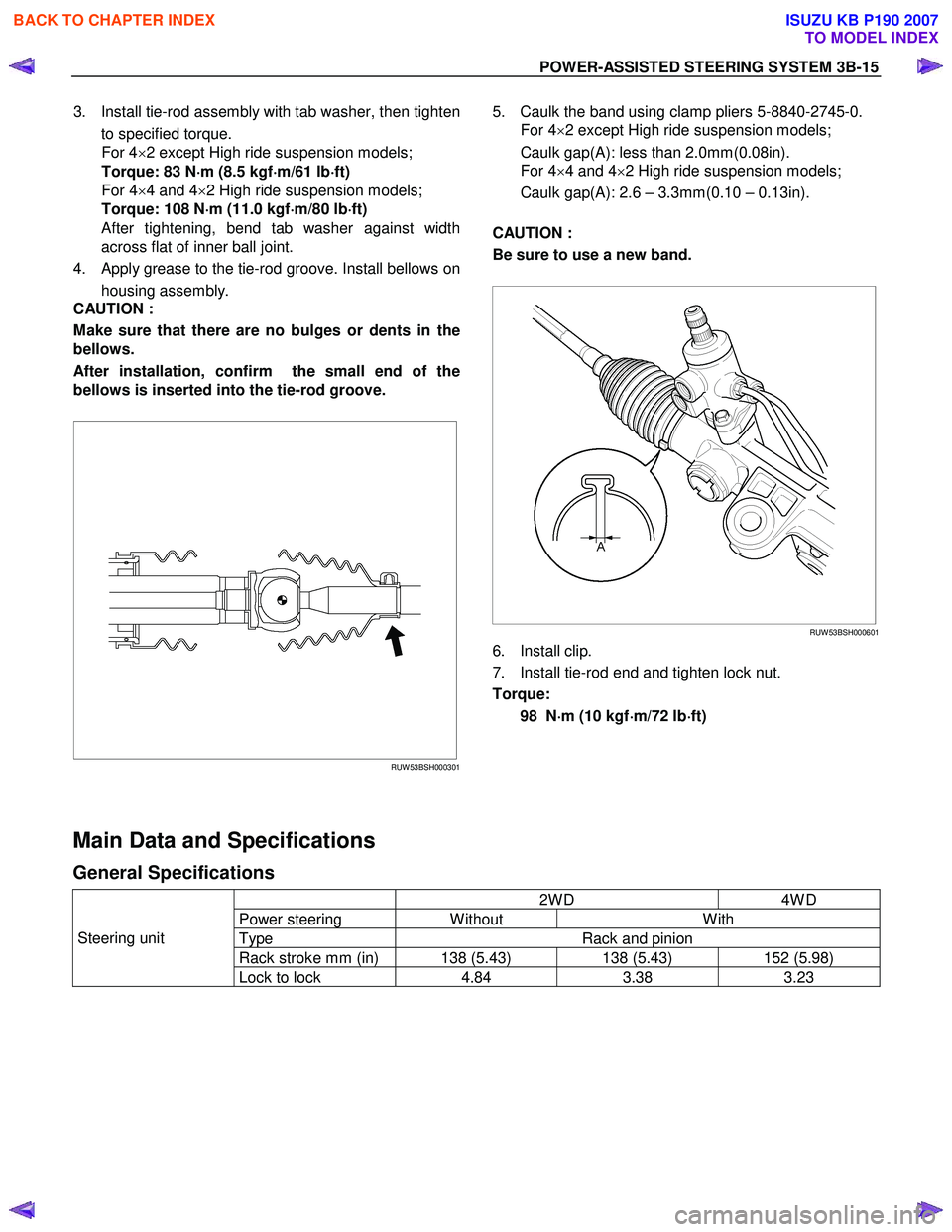
4. Apply grease to the tie-rod groove. Install bellows on housing assembly.
CAUTION :
Make sure that there are no bulges or dents in the
bellows.
After installation, confirm the small end of the
bellows is inserted into the tie-rod groove.
RUW 53BSH000301
5. Caulk the band using clamp pliers 5-8840-2745-0.
For 4 ×2 except High ride suspension models;
Caulk gap(A): less than 2.0mm(0.08in).
For 4 ×4 and 4 ×2 High ride suspension models;
Caulk gap(A): 2.6 – 3.3mm(0.10 – 0.13in).
CAUTION :
Be sure to use a new band.
RUW 53BSH000601
6. Install clip.
7. Install tie-rod end and tighten lock nut.
Torque:
98 N ⋅
⋅⋅
⋅
m (10 kgf ⋅
⋅⋅
⋅
m/72 lb ⋅
⋅⋅
⋅
ft)
Main Data and Specifications
General Specifications
2W D 4W D
Power steering W ithout W ith
Type Rack and pinion
Rack stroke mm (in) 138 (5.43) 138 (5.43) 152 (5.98)
Steering unit
Lock to lock 4.84 3.38 3.23
BACK TO CHAPTER INDEX
TO MODEL INDEX
ISUZU KB P190 2007
Page 288 of 6020
POWER-ASSISTED STEERING SYSTEM 3B-27
Supplemental Restraint System Steering Wheel & Column
Service Precaution
This steering wheel and column repair section covers
the Supplemental Restraint System (SRS) steering
column. The following repair procedures are specific to
SRS components. W hen servicing a vehicle equipped
with Supplemental Restraint System, pay close attention
to all W ARNINGS and CAUTIONS.
For detailed explanation about SRS, refer to Restraints
section.
WARNING: THIS VEHICLE HAS A SUPPLEMENTAL
RESTRAINT SYSTEM (SRS). REFER TO THE SRS
COMPONENT AND WIRING LOCATION VIEW IN
ORDER TO DETERMINE WHETHER YOU ARE
PERFORMING SERVICE ON OR NEAR THE SRS
COMPONENTS OR THE SRS WIRING. WHEN YOU
ARE PERFORMING SERVICE ON OR NEAR THE
SRS COMPONENTS OR THE SRS WIRING, REFER
TO THE SRS SERVICE INFORMATION. FAILURE TO
FOLLOW WARNINGS COULD RESULT IN POSSIBLE
AIR BAG DEPLOYMENT, PERSONAL INJURY, OR
OTHERWISE UNNECESSARY SRS SYSTEM
REPAIRS.
SAFE HANDLING OF INFLATOR MODULES
REQUIRES THE PROCEDURES DESCRIBED
BELOW TO BE FOLLOWED FOR BOTH LIVE AND
DEPLOYED MODULES.
SAFETY PRECAUTIONS MUST BE FOLLOWED
WHEN HANDLING A DEPLOYED AIR BAG
ASSEMBLY (AIR BAG). AFTER DEPLOYMENT, THE
AIR BAG ASSEMBLY (AIR BAG) SURFACE MAY
CONTAIN A SMALL AMOUNT OF SODIUM
HYDROXIDE, A BY-PRODUCT OF THE
DEPLOYMENT REACTION, THAT IS IRRITATING TO
THE SKIN AND EYES. MOST OF THE POWDER ON
THE AIR BAG ASSEMBLY (AIR BAG) IS HARMLESS.
AS A PRECAUTION, WEAR GLOVES AND SAFETY
GLASSES WHEN HANDLING A DEPLO
YED AIR BAG
ASSEMBLY, AND WASH YOUR HANDS WITH MILD
SOAP AND WATER AFTERWARDS.
WHEN CARRYING A LIVE AIR BAG ASSEMBLY,
MAKE SURE THE BAG AND TRIM COVER ARE
POINTED AWAY FROM YOU. NEVER CARRY AN AIR
BAG ASSEMBLY BY THE WIRES OR CONNECTOR
ON THE UNDERSIDE OF MODULE. IN THE CASE OF
AN ACCIDENTAL DEPLOYMENT, THE BAG WILL
THEN DEPLOY WITH MINIMAL CHANCE OF INJURY.
WHEN PLACING A LIVE AIR BAG ASSEMBLY ON
A
BENCH OR OTHER SURFACE, ALWAYS FACE THE
BAG AND TRIM COVER UP, AWAY FROM THE
SURFACE.
NEVER REST A STEERING COLUMN ASSEMBLY
ON THE STEERING WHEEL WITH THE AIR BAG
ASSEMBLY FACE DOWN AND COLUMN VERTICAL.
THIS IS NECESSARY SO THAT A FREE SPACE IS
PROVIDED TO ALLOW THE AIR BAG ASSEMBLY
TO EXPAND IN THE UNLIKELY EVENT OF
ACCIDENTAL DEPLOYMENT. OTHERWISE,
PERSONAL INJURY COULD RESULT.
TO AVOID DEPLOYMENT WHEN
TROUBLESHOOTING THE SRS SYSTEM, DO NOT
USE ELECTRICAL TEST EQUIPMENT, SUCH AS
A
BATTERY-POWERED OR A/C-POWERED VOLT-
METER, OHMMETER, ETC., OR ANY TYPE OF
ELECTRICAL EQUIPMENT OTHER THAN SPECIFIED
IN THIS MANUAL. DO NOT USE A NON-POWERED
PROBE-TYPE TESTER.
INSTRUCTIONS IN THIS MANUAL MUST BE
FOLLOWED CAREFULLY, OTHERWISE PERSONAL
INJURY MAY RESULT.
SRS Connectors
CAUTION: The special yellow color connectors are
used for the supplemental restraint system-air bag
circuit.
When removing the cable harness, do not pull the
cables. Otherwise, cable disconnection may occur.
When connecting the SRS connector, insert the
connector completely. Imperfect locking may cause
malfunction of the SRS circuit.
BACK TO CHAPTER INDEX
TO MODEL INDEX
ISUZU KB P190 2007
Page 290 of 6020
POWER-ASSISTED STEERING SYSTEM 3B-29
Removal
1. Turn the steering wheel so that the vehicle's wheels
are pointing straight ahead.
2. Turn the ignition switch to "LOCK".
3. Disconnect the battery "-" terminal cable, and wait at least 5 minutes (with SRS air bag).
4. Disconnect the yellow 2-way SRS connector located under the steering column (with SRS air bag).
CAUTION: The wheels of the vehicle must be
straight ahead and the steering column in the
"LOCK" position before disconnecting the steering
wheel. Failure to do so will cause the coil assembly
to lose its centering which will cause damage to the
coil assembly (with SRS air bag).
5. Disable the SRS (Refer to "Disabling the SRS" in this section) (with SRS air bag).
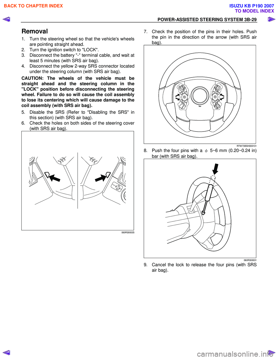
6. Check the holes on both sides of the steering cove
r
(with SRS air bag).
060R300025
7. Check the position of the pins in their holes. Push
the pin in the direction of the arrow (with SRS ai
r
bag).
RTW 73BSH000101
8. Push the four pins with a φ 5~6 mm (0.20~0.24 in)
bar (with SRS air bag).
060R300031
9. Cancel the lock to release the four pins (with SRS air bag).
BACK TO CHAPTER INDEX
TO MODEL INDEX
ISUZU KB P190 2007
Page 294 of 6020
POWER-ASSISTED STEERING SYSTEM 3B-33
Steering Wheel
Steering Wheel and Associated Parts
RTW 73BLF000101
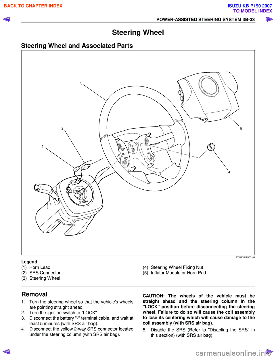
Legend
(1) Horn Lead
(2) SRS Connector
(3) Steering W heel
(4) Steering W heel Fixing Nut
(5) Inflator Module or Horn Pad
Removal
1. Turn the steering wheel so that the vehicle's wheels are pointing straight ahead.
2. Turn the ignition switch to "LOCK".
3. Disconnect the battery "-" terminal cable, and wait at least 5 minutes (with SRS air bag).
4. Disconnect the yellow 2-way SRS connector located
under the steering column (with SRS air bag).
CAUTION: The wheels of the vehicle must be
straight ahead and the steering column in the
"LOCK" position before disconnecting the steering
wheel. Failure to do so will cause the coil assembly
to lose its centering which will cause damage to the
coil assembly (with SRS air bag).
5. Disable the SRS (Refer to "Disabling the SRS" in this section) (with SRS air bag).
BACK TO CHAPTER INDEX
TO MODEL INDEX
ISUZU KB P190 2007
Page 295 of 6020
3B-34 POWER-ASSISTED STEERING SYSTEM
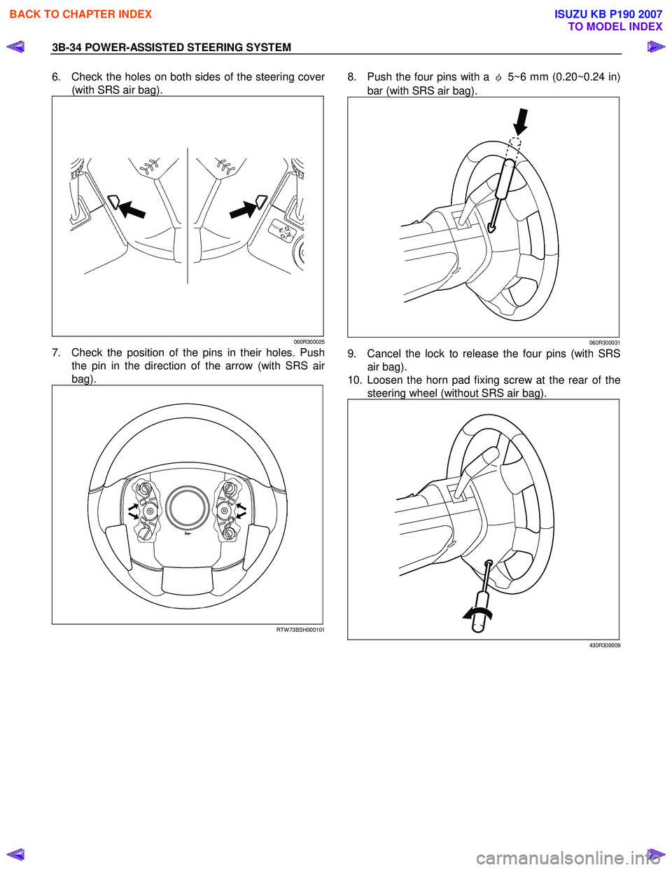
6. Check the holes on both sides of the steering cover
(with SRS air bag).
060R300025
7. Check the position of the pins in their holes. Push
the pin in the direction of the arrow (with SRS ai
r
bag).
RTW 73BSH000101
8. Push the four pins with a φ 5~6 mm (0.20~0.24 in)
bar (with SRS air bag).
060R300031
9. Cancel the lock to release the four pins (with SRS air bag).
10. Loosen the horn pad fixing screw at the rear of the steering wheel (without SRS air bag).
430R300009
BACK TO CHAPTER INDEX
TO MODEL INDEX
ISUZU KB P190 2007
Page 300 of 6020
POWER-ASSISTED STEERING SYSTEM 3B-39
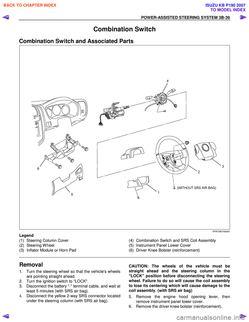
Combination Switch
Combination Switch and Associated Parts
RTW 73BLF000201
Legend
(1) Steering Column Cover
(2) Steering W heel
(3) Inflator Module or Horn Pad
(4) Combination Switch and SRS Coil Assembly
(5) Instrument Panel Lower Cover
(6) Driver Knee Bolster (reinforcement)
Removal
1. Turn the steering wheel so that the vehicle's wheels are pointing straight ahead.
2. Turn the ignition switch to "LOCK".
3. Disconnect the battery "-" terminal cable, and wait at least 5 minutes (with SRS air bag).
4. Disconnect the yellow 2-way SRS connector located
under the steering column (with SRS air bag).
CAUTION: The wheels of the vehicle must be
straight ahead and the steering column in the
"LOCK" position before disconnecting the steering
wheel. Failure to do so will cause the coil assembly
to lose its centering which will cause damage to the
coil assembly. (with SRS air bag)
5. Remove the engine hood opening lever, then remove instrument panel lower cover.
6. Remove the driver knee bolster (reinforcement).
BACK TO CHAPTER INDEX
TO MODEL INDEX
ISUZU KB P190 2007
Page 301 of 6020
3B-40 POWER-ASSISTED STEERING SYSTEM
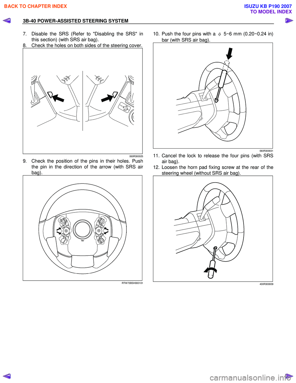
7. Disable the SRS (Refer to "Disabling the SRS" in
this section) (with SRS air bag).
8. Check the holes on both sides of the steering cover.
060R300025
9. Check the position of the pins in their holes. Push the pin in the direction of the arrow (with SRS ai
r
bag).
RTW 73BSH000101
10. Push the four pins with a φ 5~6 mm (0.20~0.24 in)
bar (with SRS air bag).
060R300031
11. Cancel the lock to release the four pins (with SRS air bag).
12. Loosen the horn pad fixing screw at the rear of the steering wheel (without SRS air bag).
430R300009
BACK TO CHAPTER INDEX
TO MODEL INDEX
ISUZU KB P190 2007