Circuit ISUZU KB P190 2007 Workshop Repair Manual
[x] Cancel search | Manufacturer: ISUZU, Model Year: 2007, Model line: KB P190, Model: ISUZU KB P190 2007Pages: 6020, PDF Size: 70.23 MB
Page 2005 of 6020
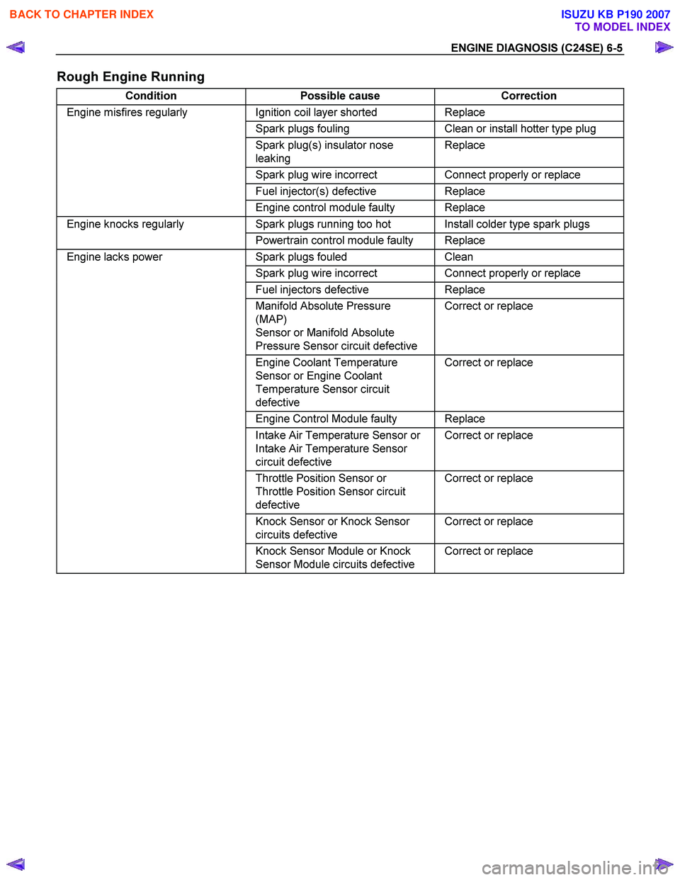
ENGINE DIAGNOSIS (C24SE) 6-5
Rough Engine Running
Condition Possible cause Correction
Engine misfires regularly Ignition coil layer shorted Replace
Spark plugs fouling Clean or install hotter type plug
Spark plug(s) insulator nose
leaking Replace
Spark plug wire incorrect Connect properly or replace
Fuel injector(s) defective Replace
Engine control module faulty Replace
Engine knocks regularly Spark plugs running too hot Install colder type spark plugs
Powertrain control module faulty Replace
Engine lacks power Spark plugs fouled Clean
Spark plug wire incorrect Connect properly or replace
Fuel injectors defective Replace
Manifold Absolute Pressure
(MAP)
Sensor or Manifold Absolute
Pressure Sensor circuit defective Correct or replace
Engine Coolant Temperature
Sensor or Engine Coolant
Temperature Sensor circuit
defective Correct or replace
Engine Control Module faulty Replace
Intake Air Temperature Sensor or
Intake Air Temperature Sensor
circuit defective Correct or replace
Throttle Position Sensor or
Throttle Position Sensor circuit
defective Correct or replace
Knock Sensor or Knock Sensor
circuits defective Correct or replace
Knock Sensor Module or Knock
Sensor Module circuits defective Correct or replace
BACK TO CHAPTER INDEX
TO MODEL INDEX
ISUZU KB P190 2007
Page 2006 of 6020

6-6 ENGINE DIAGNOSIS (C24SE)
Hesitation
Condition Possible cause Correction
Hesitation on acceleration Throttle Position Sensor
adjustment incorrect Replace throttle valve assembly
Throttle Position Sensor circuit
open or shorted Correct or replace
Excessive play in accelerator
linkage Adjust or replace
Manifold Absolute Pressure
(MAP) Sensor circuit open or
shorted Correct or replace
MAP Sensor defective Replace
Intake Air Temperature (IAT)
Sensor circuit open or shorted Correct or replace
Knock Sensor (KS) Circuit open or
shorted Correct or replace
KS
defective Replace
KS Module circuits open or
shorted Correct or replace
KS Module defective Replace
IAT Sensor defective Replace
Hesitation at high speeds
(Fuel pressure too low) Fuel tank strainer clogged Clean or replace
Fuel pipe clogged Clean or replace
Fuel filter clogged Replace
Defective fuel pump system Check and replace
Fuel Pressure Control Valve
leaking Replace
Hesitation at high speeds
(Fuel injector not working
normally) Power supply or ground circuit for
Multiport Fuel Injection System
shorted or open Check and correct or replace
Cable of Multiport Fuel Injection
System disconnected or defective Correct or replace
Hesitation at high speeds
Engine Control Module defective Replace
Throttle Position Sensor circuit
open or shorted Correct or replace
Throttle Position Sensor defective Replace
Engine Coolant Temperature
Sensor circuit open or shorted Correct or replace
Engine Coolant Temperature
Sensor defective Replace
MAP Sensor cable open or
shorted Correct or replace
MAP Sensor defective Replace
IAT Sensor circuit open or shorted Correct or replace
IAT Sensor defective Replace
KS Circuit open or shorted Correct or replace
KS defective Replace
KS Module circuit open or shorted Correct or replace
KS Module defective Replace
Throttle valve not wide opened Check and correct or replace
Air Cleaner Filter clogged Replace filter element
Power supply voltage too low Check and correct or replace
BACK TO CHAPTER INDEX
TO MODEL INDEX
ISUZU KB P190 2007
Page 2007 of 6020
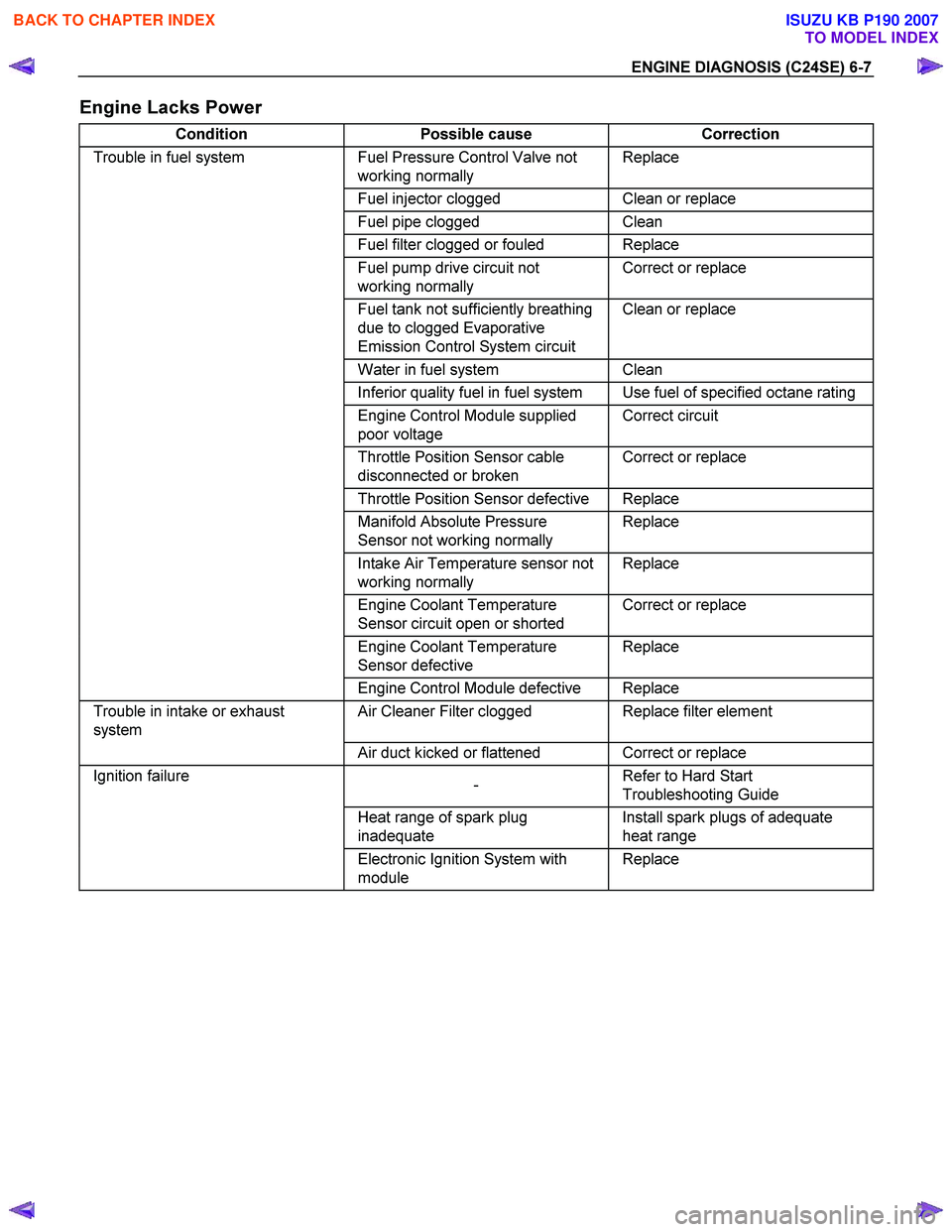
ENGINE DIAGNOSIS (C24SE) 6-7
Engine Lacks Power
Condition Possible cause Correction
Trouble in fuel system Fuel Pressure Control Valve not
working normally Replace
Fuel injector clogged Clean or replace
Fuel pipe clogged Clean
Fuel filter clogged or fouled Replace
Fuel pump drive circuit not
working normally Correct or replace
Fuel tank not sufficiently breathing
due to clogged Evaporative
Emission Control System circuit Clean or replace
Water in fuel system Clean
Inferior quality fuel in fuel system Use fuel of specified octane rating
Engine Control Module supplied
poor voltage Correct circuit
Throttle Position Sensor cable
disconnected or broken Correct or replace
Throttle Position Sensor defective Replace
Manifold Absolute Pressure
Sensor not working normally Replace
Intake Air Temperature sensor not
working normally Replace
Engine Coolant Temperature
Sensor circuit open or shorted Correct or replace
Engine Coolant Temperature
Sensor defective Replace
Engine Control Module defective Replace
Trouble in intake or exhaust
system Air Cleaner Filter clogged Replace filter element
Air duct kicked or flattened Correct or replace
Ignition failure
- Refer to Hard Start
Troubleshooting Guide
Heat range of spark plug
inadequate Install spark plugs of adequate
heat range
Electronic Ignition System with
module Replace
BACK TO CHAPTER INDEX
TO MODEL INDEX
ISUZU KB P190 2007
Page 2008 of 6020
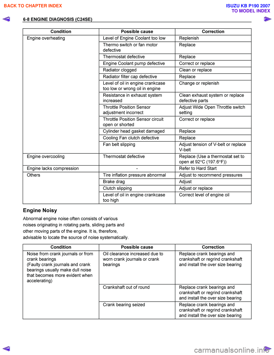
6-8 ENGINE DIAGNOSIS (C24SE)
Condition Possible cause Correction
Engine overheating Level of Engine Coolant too low Replenish
Thermo switch or fan motor
defective Replace
Thermostat
defective Replace
Engine Coolant pump defective Correct or replace
Radiator clogged Clean or replace
Radiator filter cap defective Replace
Level of oil in engine crankcase
too low or wrong oil in engine Change or replenish
Resistance in exhaust system
increased Clean exhaust system or replace
defective parts
Throttle Position Sensor
adjustment incorrect Adjust Wide Open Throttle switch
setting
Throttle Position Sensor circuit
open or shorted Correct or replace
Cylinder head gasket damaged Replace
Cooling Fan clutch defective Replace
Fan belt slipping Adjust tension of V-belt or replace
V-belt
Engine overcooling Thermostat defective Replace (Use a thermostat set to
open at 92 °C (197.6 °F))
Engine lacks compression - Refer to Hard Start
Others Tire inflation pressure abnormal Adjust to recommend pressures
Brake drag Adjust
Clutch slipping Adjust or replace
Level of oil in engine crankcase
too high Correct level of engine oil
Engine Noisy
Abnormal engine noise often consists of various
noises originating in rotating parts, sliding parts and
other moving parts of the engine. It is, therefore,
advisable to locate the source of noise systematically.
Condition Possible cause Correction
Noise from crank journals or from
crank bearings
(Faulty crank journals and crank
bearings usually make dull noise
that becomes more evident when
accelerating) Oil clearance increased due to
worn crank journals or crank
bearings Replace crank bearings and
crankshaft or regrind crankshaft
and install the over size bearing
Crankshaft out of round Replace crank bearings and
crankshaft or regrind crankshaft
and install the over size bearing
Crank bearing seized Replace crank bearings and
crankshaft or regrind crankshaft
and install the over size bearing
BACK TO CHAPTER INDEX
TO MODEL INDEX
ISUZU KB P190 2007
Page 2011 of 6020

ENGINE DIAGNOSIS (C24SE) 6-11
Abnormal Combustion
Condition Possible cause Correction
Trouble in fuel injection system Fuel pressure control valve
defective Replace
Fuel filter clogged Replace
Fuel pump clogged Clean or replace
Fuel tank or fuel pipe clogged Clean or replace
Fuel injector clogged Clean or replace
Fuel pump relay defective Replace
Power supply cable for fuel pump
loosely connected or defective Reconnect, correct or replace
Manifold Absolute Pressure
Sensor circuit open or shorted Correct or replace
Manifold Absolute Pressure
Sensor defective Replace
Engine Coolant Temperature
(ECT) Sensor circuit open or
shorted Correct or replace
ECT Sensor defective Replace
Throttle Position Sensor
adjustment incorrect Reconnect
Throttle Position Sensor defective Replace
Throttle Position Sensor
connector loosely connected Reconnect
Vehicle Speed Sensor cable
loosely connected or defective Correct or replace
Vehicle Speed Sensor loosely
fixed Fix tightly
Vehicle Speed Sensor in wrong
contact or defective Replace
Engine Control Module cable
loosely connected or defective Correct or replace
Trouble in emission control
system Heated Oxygen Sensor circuit
open (If applicable) Correct or replace
Heated Oxygen Sensor defective
(If applicable) Replace
Signal vacuum hose loosely fitted
or defective Correct or replace
ECT Sensor circuit open or
shorted Correct or replace
ECT Sensor defective Replace
Evaporative Emission Control
system (If applicable) Refer to Section 6E
Trouble in ignition system
- Refer to "Engine Lacks Power"
Trouble in cylinder head parts Carbon deposits in combustion
chamber Remove carbon
Carbon deposit on valve, valve
seat and valve guide Remove carbon
BACK TO CHAPTER INDEX
TO MODEL INDEX
ISUZU KB P190 2007
Page 2014 of 6020

6-14 ENGINE DIAGNOSIS (C24SE)
Malfunction Indicator Lamp
The instrument panel "CHECK ENGINE" Malfunction
Indicator lamp (MIL) illuminates by self diagnostic
system when the system checks the starting of
engine, or senses malfunctions.
Condition Possible cause Correction
"CHECK ENGINE" MIL does not
illuminate at the starting of engine Bulb defective Replace
MIL circuit open Correct or replace
Command signal circuit to operate
self diagnostic system shorted Correct or replace
Engine Control Module (ECM)
cable loosely connected,
disconnected or defective Correct or replace
ECM
defective Replace
“CHECK ENGINE” MIL
illuminates, and stays on Deterioration heated oxygen
sensor of internal element Replace
Heated oxygen sensor connector
terminal improper contact
(If applicable) Reconnect properly
Heated oxygen sensor lead wire
shorted (If applicable) Correct
Heated oxygen sensor circuit
open (If applicable) Correct or replace
Deterioration engine coolant
temperature sensor of internal
element Replace
Engine coolant temperature
sensor connector terminal
improper contact Reconnect properly
Engine coolant temperature
sensor lead wire shorted Correct
Engine coolant temperature
sensor circuit open Correct or replace
Throttle position sensor open or
shorted circuits Correct or replace
Deterioration of crankshaft
position sensor Replace
Crankshaft position sensor circuit
open or shorted Correct or replace
Vehicle speed sensor circuit open Correct or replace
Manifold absolute pressure sensor
circuit open or shorted Correct or replace
Intake air temperature sensor
circuit open or shorted Correct or replace
Fuel injector circuit open or shorted Correct or replace
ECM driver transistor defective Replace EPROM or ECM
Malfunctioning of ECM RAM
(Random Access Memory) or
Malfunctioning of ECM PROM
(Programmed Read Only Memory) Replace EPROM or ECM
BACK TO CHAPTER INDEX
TO MODEL INDEX
ISUZU KB P190 2007
Page 2019 of 6020
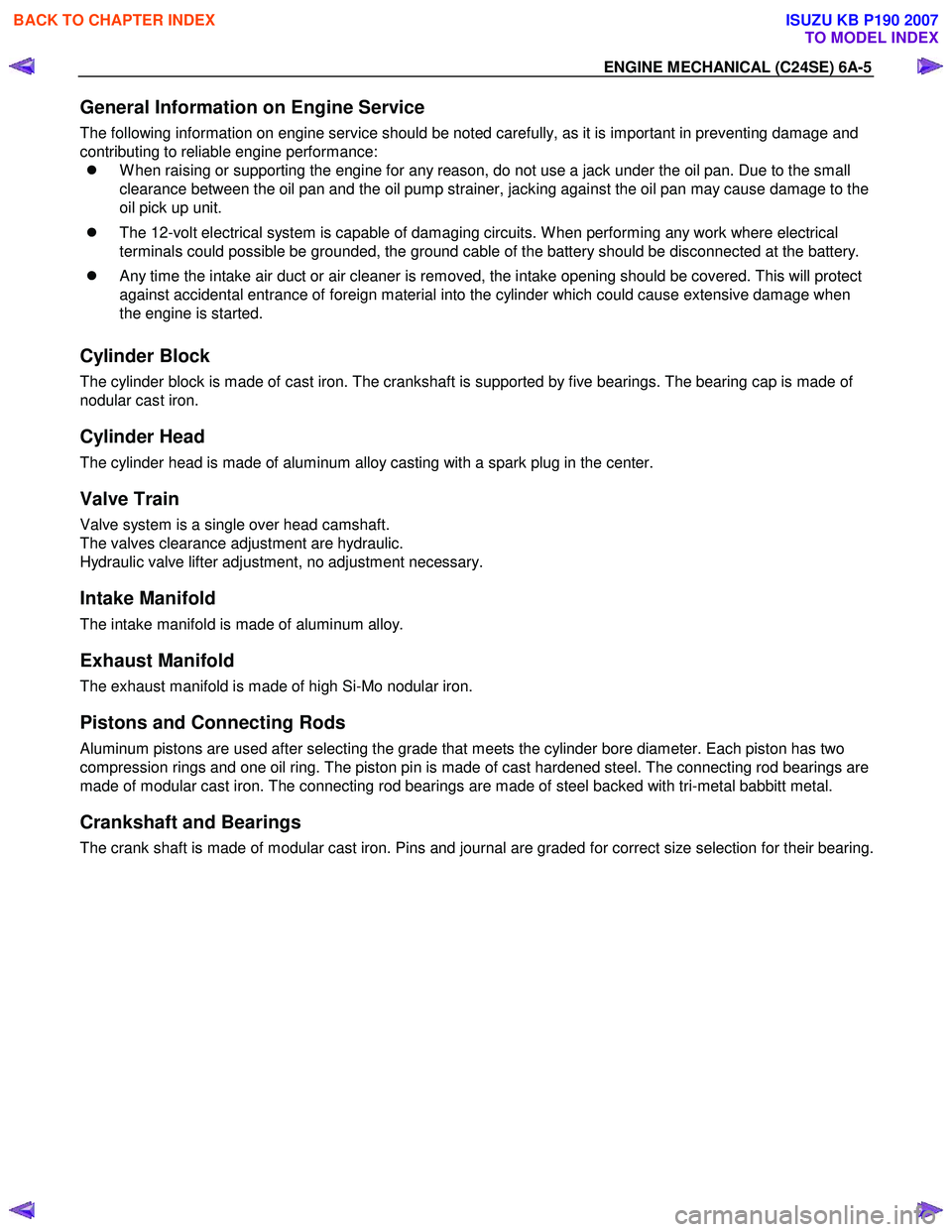
ENGINE MECHANICAL (C24SE) 6A-5
General Information on Engine Service
The following information on engine service should be noted carefully, as it is important in preventing damage and
contributing to reliable engine performance:
�z W hen raising or supporting the engine for any reason, do not use a jack under the oil pan. Due to the small
clearance between the oil pan and the oil pump strainer, jacking against the oil pan may cause damage to the
oil pick up unit.
�z The 12-volt electrical system is capable of damaging circuits. W hen performing any work where electrical
terminals could possible be grounded, the ground cable of the battery should be disconnected at the battery.
�z Any time the intake air duct or air cleaner is removed, the intake opening should be covered. This will protect
against accidental entrance of foreign material into the cylinder which could cause extensive damage when
the engine is started.
Cylinder Block
The cylinder block is made of cast iron. The crankshaft is supported by five bearings. The bearing cap is made of
nodular cast iron.
Cylinder Head
The cylinder head is made of aluminum alloy casting with a spark plug in the center.
Valve Train
Valve system is a single over head camshaft.
The valves clearance adjustment are hydraulic.
Hydraulic valve lifter adjustment, no adjustment necessary.
Intake Manifold
The intake manifold is made of aluminum alloy.
Exhaust Manifold
The exhaust manifold is made of high Si-Mo nodular iron.
Pistons and Connecting Rods
Aluminum pistons are used after selecting the grade that meets the cylinder bore diameter. Each piston has two
compression rings and one oil ring. The piston pin is made of cast hardened steel. The connecting rod bearings are
made of modular cast iron. The connecting rod bearings are made of steel backed with tri-metal babbitt metal.
Crankshaft and Bearings
The crank shaft is made of modular cast iron. Pins and journal are graded for correct size selection for their bearing.
BACK TO CHAPTER INDEX
TO MODEL INDEX
ISUZU KB P190 2007
Page 2106 of 6020

6B-2 ENGINE COOLING
General Description
Legend
1 W ater Pump
2 Thermostat
3 Radiator
4 Reserve Tank 5 Coolant Distributor
6 Cylinder Block and Head
7 Throttle Body
8 Heater
The Cooling System is a pressurized type, where the water
pump, which is cambelt driven, forces the circulation of
the coolant through the cylinder block and head. The
thermostat regulates the flow of coolant between the
radiator and the bypass circuit. The heater is part of the
bypass circuit. The throttle body pre-heat is a separate
circuit which is not regulated by the thermostat. An oil
cooler may be fitted as part of this circuit.
BACK TO CHAPTER INDEX
TO MODEL INDEX
ISUZU KB P190 2007
Page 2109 of 6020
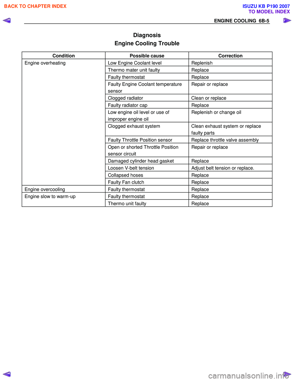
ENGINE COOLING 6B-5
Diagnosis
Engine Cooling Trouble
Condition Possible cause Correction
Engine overheating Low Engine Coolant level Replenish
Thermo mater unit faulty Replace
Faulty thermostat Replace
Faulty Engine Coolant temperature
sensor Repair or replace
Clogged radiator Clean or replace
Faulty radiator cap Replace
Low engine oil level or use of
improper engine oil Replenish or change oil
Clogged exhaust system Clean exhaust system or replace
faulty parts
Faulty Throttle Position sensor Replace throttle valve assembly
Open or shorted Throttle Position
sensor circuit Repair or replace
Damaged cylinder head gasket Replace
Loosen V-belt tension Adjust belt tension or replace.
Collapsed hoses Replace
Faulty Fan clutch Replace
Engine overcooling Faulty thermostat Replace
Engine slow to warm-up Faulty thermostat Replace
Thermo unit faulty Replace
BACK TO CHAPTER INDEX
TO MODEL INDEX
ISUZU KB P190 2007
Page 2142 of 6020
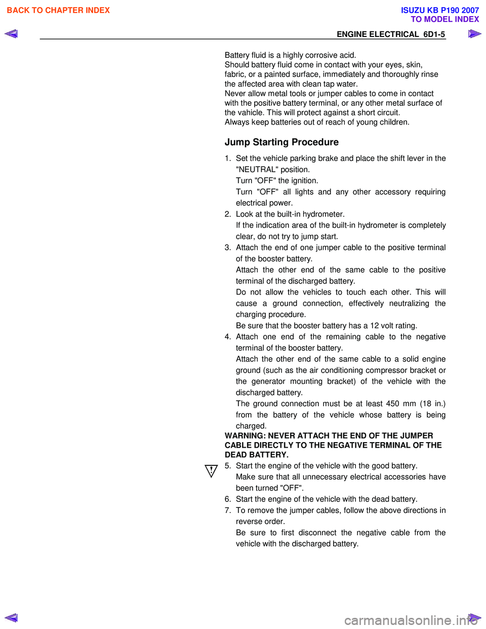
ENGINE ELECTRICAL 6D1-5
Battery fluid is a highly corrosive acid.
Should battery fluid come in contact with your eyes, skin,
fabric, or a painted surface, immediately and thoroughly rinse
the affected area with clean tap water.
Never allow metal tools or jumper cables to come in contact
with the positive battery terminal, or any other metal surface of
the vahicle. This will protect against a short circuit.
Always keep batteries out of reach of young children.
Jump Starting Procedure
1. Set the vehicle parking brake and place the shift lever in the
"NEUTRAL" position.
Turn "OFF" the ignition.
Turn "OFF" all lights and any other accessory requiring electrical power.
2. Look at the built-in hydrometer.
If the indication area of the built-in hydrometer is completel
y
clear, do not try to jump start.
3.
Attach the end of one jumper cable to the positive terminal
of the booster battery.
Attach the other end of the same cable to the positive
terminal of the discharged battery.
Do not allow the vehicles to touch each other. This will cause a ground connection, effectively neutralizing the
charging procedure.
Be sure that the booster battery has a 12 volt rating.
4.
Attach one end of the remaining cable to the negative
terminal of the booster battery.
Attach the other end of the same cable to a solid engine ground (such as the air conditioning compressor bracket o
r
the generator mounting bracket) of the vehicle with the
discharged battery.
The ground connection must be at least 450 mm (18 in.) from the battery of the vehicle whose battery is being
charged.
WARNING: NEVER ATTACH THE END OF THE JUMPER
CABLE DIRECTLY TO THE NEGATIVE TERMINAL OF THE
DEAD BATTERY.
5. Start the engine of the vehicle with the good battery.
Make sure that all unnecessary electrical accessories have been turned "OFF".
6. Start the engine of the vehicle with the dead battery.
7. To remove the jumper cables, follow the above directions in reverse order.
Be sure to first disconnect the negative cable from the vehicle with the discharged battery.
BACK TO CHAPTER INDEX
TO MODEL INDEX
ISUZU KB P190 2007