Circuit ISUZU KB P190 2007 Workshop Repair Manual
[x] Cancel search | Manufacturer: ISUZU, Model Year: 2007, Model line: KB P190, Model: ISUZU KB P190 2007Pages: 6020, PDF Size: 70.23 MB
Page 2169 of 6020

STARTING AND CHARGING SYSTEM 6D3-21
Technical Data
(mm)
Brush wear - Minimum Length 3.8
Sliprings - Minimum Diameter 26.7
Sliprings - Trueness <0.06
Pole claws - Trueness <0.05(93.25 ±0.05)
Torque N.m(kgf⋅m)
Pulley retaining nut 54-68(5.5-6.9)
Capacitor retaining screw 2.7-3.8(0.3-0.4)
Capacitor whiz nut 1.5-2.2(0.1-0.2)
B+ terminal nut M8 7.5-8.5(0.8-0.9)
B+ terminal rectifier nut 6.0-7.5(0.6-0.8)
Regulator retaining screw 1.6-2.3(0.1-0.2)
Rectifier retaining screw 1.6-2.3(0.1-0.2)
Bearing retaining plate screw 2.1-3.0(0.2-0.3)
Through bolt 3.8-5.5(0.4-0.6)
W inding resistance(between phases) (Ω )
Stator Rotor
70 Amp generator 0.086+10% 2.6 ±0.13
85 Amp generator 0.058+10% 2.6 ±0.13
90 Amp generator 0.056+10% 2.6 ±0.13
W arning lamp fault indication
Fault running Generator not
running Ignition ON Generator
Iginiton ON
Generator out cable
O/C ON
ON
Battery "S" cable O/C ONON
Battery overcharged ONON
Positive diode short OFFON
Negative diode short ONON
Positive diode open ONOFF
Negative diode open ONOFF
Phase voltage sensing ONON
cable open circuit
Power transistor
shorted ON
ON
W arnign lamp driver
O/C OFF
OFF
BACK TO CHAPTER INDEX
TO MODEL INDEX
ISUZU KB P190 2007
Page 2171 of 6020

SECTION 6E
TABLE OF CONTENTS
C24SE ENGINE DRIVEABILITY AND EMISSIONS
ABBREVIATIONS CHARTS ......................... 6E-6
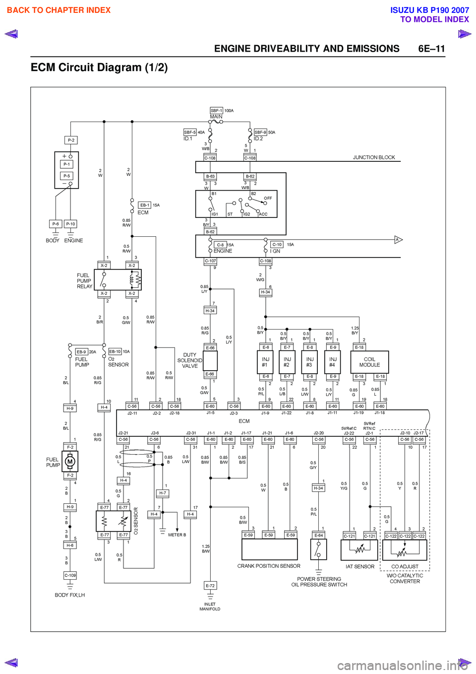
ECM Circuit Diagram (1/2) ............................ 6E-11
ECM Circuit Diagram (2/2) ............................ 6E-12
GROUND POINT CHART - LHD G.EXP (1/4) 6E-13
GROUND POINT CHART - RHD G.EXP (1/4) 6E-17
LOCATION ................................................... 6E-21
CABLE HARNESS & CONNECTOR LOCATION .............................................. 6E-23
CABLE HARNESS & CONNECTOR LOCATION - LHD ................................... 6E-24
CABLE HARNESS & CONNECTOR LOCATION - RHD ................................... 6E-25
CONNECTOR LIST ...................................... 6E-28
RELAY AND FUSE ....................................... 6E-30
RELAY AND FUSE BOX LOCATION (LHD & RHD) ........................................... 6E-30
FUSE AND RELAY LOCATION (LHD & RHD) 6E-32
ECM WIRING DIAGRAM (1/9) ..................... 6E-33
ECM WIRING DIAGRAM (2/9) ..................... 6E-34
ECM WIRING DIAGRAM (3/9) ..................... 6E-35
ECM WIRING DIAGRAM (4/9) ..................... 6E-36
ECM WIRING DIAGRAM (5/9) ..................... 6E-37
ECM WIRING DIAGRAM (6/9) ..................... 6E-38
ECM WIRING DIAGRAM (7/9) ..................... 6E-39
ECM WIRING DIAGRAM (8/9) ..................... 6E-40
ECM WIRING DIAGRAM (9/9) ..................... 6E-41
ECM CONNECTOR PIN ASSIGNMENT & OUTPUT SIGNAL .................................... 6E-42
GENERAL DESCRIPTION FOR ECM AND SENSORS ............................................... 6E-48
Engine Control Module (ECM) ................... 6E-48
Manifold Absolute Pressure (MAP) Sensor 6E-48
Throttle Position Sensor (TPS) .................. 6E-49
Idle Air Control (IAC) Valve ....................... 6E-49
Crankshaft Position (CKP) Sensor ............ 6E-50
Knock Sensor (KS) .................................... 6E-50
Engine Coolant Temperature (ECT) Sensor 6E-50
Intake Air Temperature (IAT) Sensor ........ 6E-51
Vehicle Speed Sensor (VSS) .................... 6E-51
Heated Oxygen (O
2) Sensor ..................... 6E-51
GENERAL DESCRIPTION FOR FUEL METERING .............................................. 6E-52 Battery Voltage Correction Mode ............... 6E-52
Clear Flood Mode ...................................... 6E-52
Deceleration Fuel Cutoff (DFCO) Mode .... 6E-52
Engine Speed/ Vehicle Speed/ Fuel Disable Mode ........................................................ 6E-52
Acceleration Mode ..................................... 6E-52
Fuel Cutoff Mode ....................................... 6E-52
Starting Mode ............................................ 6E-52
Run Mode .................................................. 6E-52
Fuel Metering System Components .......... 6E-53
Fuel Injector ............................................... 6E-53
Fuel Pressure Regulator ............................ 6E-53
Fuel Rail ..................................................... 6E-53
Fuel Pump Electrical Circuit ....................... 6E-53
Thottle Body Unit ....................................... 6E-53
GENERAL DESCRIPTION FOR ELECTRIC IGNITION SYSTEM ................................. 6E-54
Spark Plug ................................................. 6E-54
GENERAL DESCRIPTION FOR EVAPORATIVE EMISSION SYSTEM ............................... 6E-57
EVAP Emission Control System Purpose .. 6E-57
EVAP Emission Control System Operation 6E-57
System Fault Detection .............................. 6E-57
POSITIVE CRANKCASE VENTILATION (PCV) SYSTEM .................................................. 6E-59
Crankcase Ventilation System Purpose .... 6E-59
A/C CLUTCH DIAGNOSIS ........................ 6E-60
A/C Clutch Circuit Operation ...................... 6E-60
A/C Clutch Circuit Purpose ........................ 6E-60
A/C Request Signal ................................... 6E-60
ISUZU STRATEGY BASED DIAGNOSTICS 6E-61
Overview .................................................... 6E-61
STRATEGY BASED DIAGNOSTICS CHART 6E-61 Diagnostic Thought Process ...................... 6E-62
1. Verify the Complaint .............................. 6E-62
2. Perform Preliminary Checks .................. 6E-62
3. Check Bulletins and Troubleshooting Hints 6E-63
4. Perform Service Manual Diagnostic Checks 6E-63
5a and 5b. Perform Service Manual Diagnostic Procedures .............................................. 6E-63
5c. Technician Self Diagnoses .................. 6E-63
5d. Intermittent Diagnosis .......................... 6E-64
6 E –1
E N GINE DRIV EABILITY AND E M IS SIONS
BACK TO CHAPTER INDEX
TO MODEL INDEX
ISUZU KB P190 2007
Page 2172 of 6020

6E–2 ENGINE DRIVEABILITY AND EMISSIONS
5e. Vehicle Operates as Designed ............ 6E-65
6. Re-examine the complaint ..................... 6E-66
7. Repair and Verify Fix ............................. 6E-66
GENERAL SERVICE INFORMATION .......... 6E-67 On-Board Diagnostic (OBD) ...................... 6E-68
On-Board Diagnostic Tests ....................... 6E-68
The Diagnostic Executive .......................... 6E-68
Diagnostic Information ............................... 6E-68
Check Engine Lamp .................................. 6E-68
Data Link Connector (DLC) ....................... 6E-68
Tech 2 Operating Flow Cart (Start Up) ...... 6E-70
TYPICAL SCAN DATA & DEFINITIONS (ENGINE DATA) ......................................... 6E-72
TYPICAL SCAN DATA & DEFINITIONS (O2 SENSOR DATA) .................................. 6E-74
MISCELLANEOUS TEST ............................. 6E-76
PLOTTING SNAPSHOT GRAPH ................. 6E-78 Plotting Graph Flow Chart (Plotting graph after obtaining vehicle information) .................. 6E-79
Flow Chart for Snapshot Replay (Plotting Graph) ....................................... 6E-80
SNAPSHOT DISPLAY WITH TIS2000 ......... 6E-81
ON-BOARD DIAGNOSTIC (OBD) SYSTEM CHECK 6E-98
Circuit Description ......................................... 6E-90
Diagnostic Aids ............................................. 6E-90
Test Description ............................................ 6E-90
ON-BOARD DIAGNOSTIC (OBD) SYSTEM CHECK .................................................... 6E-91
NO CHECK ENGINE LAMP (MIL) ................ 6E-94 Circuit Description ..................................... 6E-94
Diagnostic Aids .......................................... 6E-94
No Check Engine Lamp (MIL) ................... 6E-94
CHECK ENGINE LAMP (MIL) “ON” STEADY 6E-96 Circuit description ...................................... 6E-96
Diagnostic Aids .......................................... 6E-96
Check Engine Lamp (MIL) “ON” Steady .... 6E-96
FUEL METERING SYSTEM CHECK ........... 6E-98
FUEL INJECTOR COIL TEST PROCEDURE AND FUEL INJECTOR BALANCE TEST
PROCEDURE ............................................. 6E-98
Test Description ......................................... 6E-98
Injector Coil Test Procedure (Steps 1-6) and Injector Balance Test Procedure
(Steps 7-11) ............................................. 6E-99
Injector Coil Test Procedure (Steps 1-6) and Injector Balance Test Procedure
(Steps 7-11) ............................................. 6E-100
FUEL SYSTEM ELECTRICAL TEST ........... 6E-103 Circuit Description ..................................... 6E-103
Diagnostic Aids .......................................... 6E-104 Fuel Pressure Relief Procedure ................. 6E-104
Fuel Pressure Gauge Installation .............. 6E-104
Fuel System Electrical Test ....................... 6E-104
FUEL SYSTEM DIAGNOSIS ........................ 6E-108 Circuit Description ...................................... 6E-108
Test Description ......................................... 6E-108
Fuel Pressure Relief Procedure ................. 6E-109
Fuel Pressure Gauge Installation .............. 6E-109
Fuel System Diagnosis .............................. 6E-110
ECM DIAGNOSTIC TROUBLE CODES (DTC) 6E-113
DIAGNOSTIC TROUBLE CODE (DTC) P0107 MANIFOLD ABSOLUTE PRESSURE
CIRCUIT LOW INPUT ................................ 6E-119
Circuit Description ...................................... 6E-119
Diagnostic Aids .......................................... 6E-119
Diagnostic Trouble Code (DTC) P0107 Manifold Absolute Pressure Circuit Low
Input ......................................................... 6E-120
DIAGNOSTIC TROUBLE CODE (DTC) P0108 MANIFOLD ABSOLUTE PRESSURE
CIRCUIT HIGH INPUT ............................... 6E-123
Circuit Description ...................................... 6E-123
Diagnostic Aids .......................................... 6E-124
Diagnostic Trouble Code (DTC) P0108 Manifold Absolute Pressure Circuit High
Input ......................................................... 6E-124
DIAGNOSTIC TROUBLE CODE (DTC) P0112 INTAKE AIR TEMPERATURE SENSOR LOW
INPUT ......................................................... 6E-127
Circuit Description ...................................... 6E-127
Diagnostic Aids .......................................... 6E-127
Diagnostic Trouble Code (DTC) P0112 Intake Air Temperature Sensor Low Input 6E-128
DIAGNOSTIC TROUBLE CODE (DTC) P0113 INTAKE AIR TEMPERATURE SENSOR HIGH
INPUT ......................................................... 6E-131
Circuit Description ...................................... 6E-131
Diagnostic Aids .......................................... 6E-131
Diagnostic Trouble Code (DTC) P0113 Intake Air Temperature Sensor High Input 6E-132
DIAGNOSTIC TROUBLE CODE (DTC) P0117 ENGINE COOLANT TEMPERATURE
SENSOR LOW INPUT ................................ 6E-136
Circuit Description ...................................... 6E-136
Diagnostic Aids .......................................... 6E-136
Diagnostic Trouble Code (DTC) P0117 Engine Coolant Temperature Sensor Low
Input ......................................................... 6E-137
DIAGNOSTIC TROUBLE CODE (DTC) P0118 ENGINE COOLANT TEMPERATURE
SENSOR HIGH INPUT ............................... 6E-139
Circuit Description ...................................... 6E-139
BACK TO CHAPTER INDEX
TO MODEL INDEX
ISUZU KB P190 2007
Page 2173 of 6020

ENGINE DRIVEABILITY AND EMISSIONS 6E–3
Diagnostic Aids .......................................... 6E-139
Diagnostic Trouble Code (DTC) P0118 Engine Coolant Temperature Sensor High
Input ......................................................... 6E-140
DIAGNOSTIC TROUBLE CODE (DTC) P0122 THROTTLE POSITION SENSOR LOW
INPUT ......................................................... 6E-143
Circuit Description ..................................... 6E-143
Diagnostic Aids .......................................... 6E-143
Diagnostic Trouble Code (DTC) P0122 Throttle Position Sensor Low Input ....................... 6E-144
DIAGNOSTIC TROUBLE CODE (DTC) P0123 THROTTLE POSITION SENSOR HIGH
INPUT ...................................................... 6E-147
Circuit Description ..................................... 6E-147
Diagnostic Aids .......................................... 6E-147
Diagnostic Trouble Code (DTC) P0123 Throttle Position Sensor High Input ...................... 6E-148
DIAGNOSTIC TROUBLE CODE (DTC) P0131 O
2 SENSOR CIRCUIT LOW VOLTAGE
(BANK 1 SENSOR 1) ................................. 6E-150
Circuit Description ..................................... 6E-150
Diagnostic Aids .......................................... 6E-150
Diagnostic Trouble Code (DTC) P0131 O
2 Sensor Circuit Low Voltage (Bank 1 Sensor 1)
6E-160
DIAGNOSTIC TROUBLE CODE (DTC) P0132 O
2
SENSOR CIRCUIT HIGH VOLTAGE (BANK 1
SENSOR 1) ................................................ 6E-155
Circuit Description ..................................... 6E-155
Diagnostic Aids .......................................... 6E-155
Diagnostic Trouble Code (DTC) P0132 O
2 Sensor Circuit High Voltage
(Bank 1 Sensor 1) .................................... 6E-156
DIAGNOSTIC TROUBLE CODE (DTC) P0134 O
2 SENSOR NO ACTIVITY DEFECTED
(BANK 1 SENSOR 1) ................................. 6E-159
Circuit Description ..................................... 6E-159
Diagnostic Aids .......................................... 6E-160
Diagnostic Trouble Code (DTC) P0134 O
2 Sensor Circuit No Activity Detected
(Bank 1 Sensor 1) .................................... 6E-160
DIAGNOSTIC TROUBLE CODE (DTC) P0135 O
2 SENSOR HEATER CIRCUIT
(BANK 1 SENSOR 1) ................................. 6E-163
Circuit Description ..................................... 6E-163
Diagnostic Aids .......................................... 6E-164
Diagnostic Trouble Code (DTC) P0135 O
2 Sensor Heater Circuit (Bank 1 Sensor 1) 6E-164
DIAGNOSTIC TROUBLE CODE (DTC) P0201 INJECTOR 1 CONTROL CIRCUIT ............. 6E-167
DIAGNOSTIC TROUBLE CODE (DTC) P0202 INJECTOR 2 CONTROL CIRCUIT ............. 6E-167
DIAGNOSTIC TROUBLE CODE (DTC) P0203 INJECTOR 3 CONTROL CIRCUIT ............. 6E-167
DIAGNOSTIC TROUBLE CODE (DTC) P0204 INJECTOR 4 CONTROL CIRCUIT ............. 6E-167
Circuit Description ...................................... 6E-167
Diagnostic Aids .......................................... 6E-168
Diagnostic Trouble Code (DTC) P0201 Injector 1 Control Circuit .......................... 6E-168
Diagnostic Trouble Code (DTC) P0202 Injector 2 Control Circuit .......................... 6E-168
Diagnostic Trouble Code (DTC) P0203 Injector 3 Control Circuit .......................... 6E-168
Diagnostic Trouble Code (DTC) P0204 Injector 4 Control Circuit .......................... 6E-168
DIAGNOSTIC TROUBLE CODE (DTC) P0325 KNOCK SENSOR (KS) MODULE CIRCUIT 6E-174
Circuit Description ...................................... 6E-174
Diagnostic Aids .......................................... 6E-174
Diagnostic Trouble Code (DTC) P0325 Knock
Sensor Module Circuit ............................. 6E-174
DIAGNOSTIC TROUBLE CODE (DTC) P0327 KNOCK SENSOR (KS) CIRCUIT ............... 6E-177
Circuit Description ...................................... 6E-177
Diagnostic Aids .......................................... 6E-177
Diagnostic Trouble Code (DTC) P0327 Knock Sensor Circuit ............................... 6E-178
DIAGNOSTIC TROUBLE CODE (DTC) P0336 CRANKSHAFT POSITION (CKP) SENSOR
CIRCUIT RANGE/PERFORMANCE (58X) . 6E-180
DIAGNOSTIC TROUBLE CODE (DTC) P0337 CRANKSHAFT POSITION (CKP) SENSOR
CIRCUIT LOW INPUT (58X) ...................... 6E-180
Circuit Description ...................................... 6E-180
Diagnostic Aids .......................................... 6E-181
Diagnostic Trouble Code (DTC) P0336 Crankshaft Position Sensor Circuit
Range/performance (58x) ........................ 6E-181
Diagnostic Trouble Code (DTC) P0337 Crankshaft Position Sensor Circuit Low
Input (58x) ............................................... 6E-181
DIAGNOSTIC TROUBLE CODE (DTC) P0351 IGNITION 1 CONTROL CIRCUIT ............... 6E-186
DIAGNOSTIC TROUBLE CODE (DTC) P0352 IGNITION 2 CONTROL CIRCUIT ............... 6E-186
Circuit Description ...................................... 6E-186
Diagnostic Aids .......................................... 6E-186
Diagnostic Trouble Code (DTC) P0351 Ignition 1 Control Circuit .......................... 6E-187
Diagnostic Trouble Code (DTC) P0352 Ignition 2 Control Circuit .......................... 6E-187
BACK TO CHAPTER INDEX
TO MODEL INDEX
ISUZU KB P190 2007
Page 2174 of 6020

6E–4 ENGINE DRIVEABILITY AND EMISSIONS
DIAGNOSTIC TROUBLE CODE (DTC) P0443 EVAPORATIVE (EVAP) EMISSION CONTROL
SYSTEM PURGE CONTROL CIRCUIT ..... 6E-191
Circuit Description ..................................... 6E-191
Diagnostic Aids .......................................... 6E-191
Diagnostic Trouble Code (DTC) P0443 EVAP Emission Control System Purge
Control Circuit .......................................... 6E-192
DIAGNOSTIC TROUBLE CODE (DTC) P0502 VEHICLE SPEED SENSOR (VSS) CIRCUIT
LOW INPUT ................................................ 6E-195
Circuit Description ..................................... 6E-195
Diagnostic Aids .......................................... 6E-195
Diagnostic Trouble Code (DTC) P0502 Vehicle Speed Sensor Circuit Low Input . 6E-196
DIAGNOSTIC TROUBLE CODE (DTC) P0562 SYSTEM VOLTAGE LOW .......................... 6E-202
Circuit Description ..................................... 6E-202
Diagnostic Aids .......................................... 6E-202
Diagnostic Trouble Code (DTC) P0562 System Voltage Low ............................................. 6E-202
DIAGNOSTIC TROUBLE CODE (DTC) P0563 SYSTEM VOLTAGE HIGH ......................... 6E-204
Circuit Description ..................................... 6E-204
Diagnostic Aids .......................................... 6E-204
Diagnostic Trouble Code (DTC) P0563 System Voltage High ............................................ 6E-204
DIAGNOSTIC TROUBLE CODE (DTC) P0601 ECM MEMORY CHECKSUM ..................... 6E-206
Circuit Description ..................................... 6E-206
Diagnostic Aids .......................................... 6E-206
Diagnostic Trouble Code (DTC) P0601 ECM Memory Checksum .................................. 6E-206
DIAGNOSTIC TROUBLE CODE (DTC) P0602 ECU PROGRAMMING ERROR ................. 6E-207
Circuit Description ..................................... 6E-207
Diagnostic Aids .......................................... 6E-207
Diagnostic Trouble Code (DTC) P0602 ECU Programming Error .................................. 6E-207
DTC P0650 MALFUNCTION INDICATOR LAMP (MIL) CONTOROL CIRCUIT MALFUNCTION 6E-208
Circuit Description ..................................... 6E-208
Diagnostic Aids .......................................... 6E-208
Diagnostic Trouble Code (DTC) P0650 Malfunction Indicator Lamp (MIL) Control
Circuit Malfunction ................................... 6E-209
DIAGNOSTIC TROUBLE CODE (DTC) P1167 FUEL SUPPLY SYSTEM RICH DURING
DECELERATION FUEL CUT OFF ............. 6E-211
Circuit Description ..................................... 6E-211
Diagnostic Aids .......................................... 6E-211
Diagnostic Trouble Code (DTC) P1167 Fuel Supply System Rich During
Deceleration Fuel Cutoff .......................... 6E-212
DIAGNOSTIC TROUBLE CODE (DTC) P1171 FUEL SUPPLY SYSTEM LEAN DURING
POWER ENRICHMENT ............................. 6E-214
Circuit Description ...................................... 6E-214
Diagnostic Aids .......................................... 6E-215
Diagnostic Trouble Code (DTC) P1171 Fuel Supply System Lean During Power
Enrichment .............................................. 6E-215
DIAGNOSTIC TROUBLE CODE (DTC) P1625 ECM SYSTEM RESET ............................... 6E-217
Circuit Description ...................................... 6E-217
Diagnostic Aids .......................................... 6E-217
Diagnostic Trouble Code (DTC) P1625 ECM System Reset .......................................... 6E-217
DIAGNOSTIC TROUBLE CODE (DTC) P1626 IMMOBILIZER NO SIGNAL ........................ 6E-218
Circuit Description ...................................... 6E-218
Diagnostic Aids .......................................... 6E-218
Diagnostic Trouble Code (DTC) P1626 Immobilizer No Signal .............................. 6E-219
DIAGNOSTIC TROUBLE CODE (DTC) P1631 IMMOBILIZER WRONG SIGNAL ............... 6E-222
Circuit Description ...................................... 6E-222
Diagnostic Aids .......................................... 6E-222
Diagnostic Trouble Code (DTC) P1631 Immobilizer Wrong Signal ........................ 6E-223
DIAGNOSTIC TROUBLE CODE (DTC) P1648 WRONG SECURITY CODE ENTERED .. 6E-224
Circuit Description ...................................... 6E-224
Diagnostic Aids .......................................... 6E-224
Diagnostic Trouble Code (DTC) P1648 Wrong Security Code Entered ............................ 6E-225
DIAGNOSTIC TROUBLE CODE (DTC) P1649 IMMOBILIZER FUNCTION NOT
PROGRAMMED ......................................... 6E-226
Circuit Description ...................................... 6E-226
Diagnostic Aids .......................................... 6E-226
Diagnostic Trouble Code (DTC) P1649 Immobilizer Function Not Programmed ... 6E-227
DIAGNOSTIC TROUBLE CODE (DTC) P1693 TACHOMETER OUTPUT LOW VOLTAGE 6E-228
Circuit Description ...................................... 6E-228
Diagnostic Aids .......................................... 6E-228
Diagnostic Trouble Code (DTC) P1693 Tachometer Output Low Voltage ............. 6E-229
SYMPTOM DIAGNOSIS ............................... 6E-232
PRELIMINARY CHECKS ............................. 6E-232
VISUAL/PHYSICAL CHECK ......................... 6E-232
INTERMITTENT ........................................... 6E-232
BACK TO CHAPTER INDEX
TO MODEL INDEX
ISUZU KB P190 2007
Page 2181 of 6020

ENGINE DRIVEABILITY AND EMISSIONS 6E–11
ECM Circuit Diagram (1/2)
BACK TO CHAPTER INDEX
TO MODEL INDEX
ISUZU KB P190 2007
Page 2182 of 6020

6E–12 ENGINE DRIVEABILITY AND EMISSIONS
ECM Circuit Diagram (2/2)
BACK TO CHAPTER INDEX
TO MODEL INDEX
ISUZU KB P190 2007
Page 2218 of 6020

6E–48 ENGINE DRIVEABILITY AND EMISSIONS
GENERAL DESCRIPTION FOR ECM AND
SENSORS
Engine Control Module (ECM)
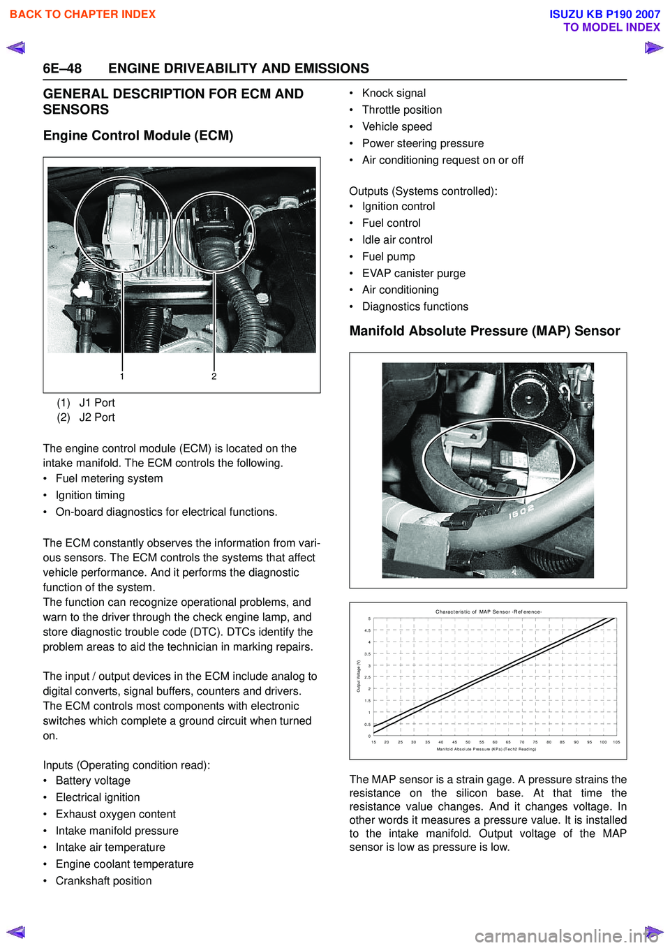
The engine control module (ECM) is located on the
intake manifold. The ECM controls the following.
• Fuel metering system
• Ignition timing
• On-board diagnostics for electrical functions.
The ECM constantly observes the information from vari-
ous sensors. The ECM controls the systems that affect
vehicle performance. And it performs the diagnostic
function of the system.
The function can recognize operational problems, and
warn to the driver through the check engine lamp, and
store diagnostic trouble code (DTC). DTCs identify the
problem areas to aid the technician in marking repairs.
The input / output devices in the ECM include analog to
digital converts, signal buffers, counters and drivers.
The ECM controls most components with electronic
switches which complete a ground circuit when turned
on.
Inputs (Operating condition read):
• Battery voltage
• Electrical ignition
• Exhaust oxygen content
• Intake manifold pressure
• Intake air temperature
• Engine coolant temperature
• Crankshaft position • Knock signal
• Throttle position
• Vehicle speed
• Power steering pressure
• Air conditioning request on or off
Outputs (Systems controlled):
• Ignition control
• Fuel control
• Idle air control
• Fuel pump
• EVAP canister purge
• Air conditioning
• Diagnostics functions
Manifold Absolute Pressure (MAP) Sensor
The MAP sensor is a strain gage. A pressure strains the
resistance on the silicon base. At that time the
resistance value changes. And it changes voltage. In
other words it measures a pressure value. It is installed
to the intake manifold. Output voltage of the MAP
sensor is low as pressure is low.
(1) J1 Port
(2) J2 Port
12
C harac t eris t ic of MAP Sens or -R ef erenc e-
0
0.5 1
1.5 2
2.5
3
3.5 4
4.5 5
15 20 25 30 35 40 45 50 55 60 65 70 75 80 85 90 95 100 105 Manifold Abs olute Press ure (KPa) (T ec h2 Reading)
Output Voltage (V)
BACK TO CHAPTER INDEX
TO MODEL INDEX
ISUZU KB P190 2007
Page 2223 of 6020

ENGINE DRIVEABILITY AND EMISSIONS 6E–53
Fuel Metering System Components
The fuel metering system is made up of the following
parts.
• Fuel injector
• Throttle body
•Fuel rail
• Fuel pressure regulator
•ECM
• Crankshaft position (CKP) sensor
• Idle air control (IAC) valve
•Fuel pump
Fuel Injector
The group fuel injection fuel injector is a solenoid
operated device controlled by the ECM. The ECM
energizes the solenoid, which opens a valve to allow
fuel delivery.
The fuel is injected under pressure in a conical spray
pattern at the opening of the intake valve. Excess fuel
not used by the injectors passes through the fuel
pressure regulator before being returned to the fuel
tank.
Fuel Pressure Regulator
The fuel pressure regulator is a diaphragm-operated
relief valve mounted on the fuel rail with fuel pump
pressure on one side and manifold pressure on the
other side. The fuel pressure regulator maintains the
fuel pressure available to the injector at three times
barometric pressure adjusted for engine load. It may be
serviced separately.
If the pressure is too low or poor performance, DTC
P0131 or P1171 will be the result. If the pressure is too
high, DTC P0132 or P1167 will be the result. Refer to
Fuel System Diagnosis for information on diagnosing
fuel pressure conditions.
Fuel Rail
The fuel rail is mounted to the top of the engine and
distributes fuel to the individual injectors. Fuel is
delivered to the fuel inlet tube of the fuel rail by the fuel
lines. The fuel goes through the fuel rail to the fuel
pressure regulator. The fuel pressure regulator
maintains a constant fuel pressure at the injectors.
Remaining fuel is then returned to the fuel tank.
Fuel Pump Electrical Circuit
When the key is first turned ON, the ECM energizes the
fuel pump relay for two seconds to build up the fuel
pressure quickly. If the engine is not started within two
seconds, the ECM shuts the fuel pump off and waits
until the engine is cranked. When the engine is cranked
and the 58X crankshaft position signal has been
detected by the ECM, the ECM supplies 12 volts to the
fuel pump relay to energize the electric in-tank fuel
pump.
An inoperative fuel pump will cause a “no-start”
condition. A fuel pump which does not provide enough pressure will result in poor performance.
Thottle Body Unit
The throttle body has a throttle plate to control the
amount of air delivered to the engine. The Thottle
position sensor and IAC valve are also mounted on the
throttle body.
Vacuum ports located behind the throttle plate provide
the vacuum signals needed by various components.
Engine coolant is directed through a coolant cavity in
the throttle body to warm the throttle valve and to
prevent icing.
BACK TO CHAPTER INDEX
TO MODEL INDEX
ISUZU KB P190 2007
Page 2227 of 6020

ENGINE DRIVEABILITY AND EMISSIONS 6E–57
GENERAL DESCRIPTION FOR
EVAPORATIVE EMISSION SYSTEM
EVAP Emission Control System Purpose
The basic evaporative emission control system used on
the charcoal canister storage method. The method
transfers fuel vapor from the fuel tank to an activated
carbon (charcoal) storage devise to hold the vapors
when the vehicle is not operating.
The canister is located on the rear axle housing by the
frame cross-member.
When the engine is running, the fuel vapor is purged
from the carbon element by intake air flow and
consumed in the normal combustion process.
EVAP Emission Control System Operation
The EVAP canister purge is controlled by a solenoid
valve that allows the manifold vacuum to purge the
canister. The engine control module (ECM) supplies a
ground to energize the solenoid valve (purge on). The
EVAP purge solenoid control is pulse-width modulated
(PWM) (turned on and off several times a second). The
duty cycle (pulse width) is determined by engine
operating conditions including load, throttle position,
coolant temperature and ambient temperature. The duty
cycle is calculated by the ECM. the output is
commanded when the appropriate conditions have
been met. These conditions are:
• The engine is fully warmed up.
• The engine has been running for a specified time.
• The IAT reading is above 10°C (50°F).
• Purge/Vacuum Hoses. Made of rubber compounds, these hoses route the gasoline fumes from their
sources to the canister and from the canister to the
intake air flow.
• EVAP Canister. Mounted on a bracket ahead of the fuel tank, the canister stores fuel vapors until the
ECM determined that engine conditions are right for
them to be removed and burned.
Poor idle, stalling and Poor driveability can be caused
by:
• A malfunctioning purge solenoid.
• A damaged canister.
• Hoses that are split, cracked, or not connected properly.
System Fault Detection
The EVAP leak detection strategy is based on applying
vacuum to the EVAP system and monitoring vacuum
decay. At an appropriate time, the EVAP purge solenoid
is turned “ON,” allowing the engine vacuum to draw a
small vacuum on the entire evaporative emission
system.
After the desired vacuum level has been achieved, the
EVAP purge solenoid is turned “OFF,” sealing the
system. A leak is detected by monitoring for a decrease
in vacuum level over a given time period, all other
variables remaining constant.
If the desired vacuum level cannot be achieved in the
test described above, a large leak or a faulty EVAP
purge control solenoid valve is indicated.
Leaks can be caused by the following conditions:
• Missing or faulty fuel cap
• Disconnected, damaged, pinched, or blocked EVAP purge line
• Disconnected, damaged, pinched, or blocked fuel tank vapor line
• Disconnected or faulty EVAP purge control solenoid valve
• Open ignition feed circuit to the purge solenoid
(1) Purge Solenoid Valve
(2) From Canistor to Purge Solenoid
(3) From Purge Solenoid to Intake
(1) Canistor
(2) Air Separator
132
12
BACK TO CHAPTER INDEX
TO MODEL INDEX
ISUZU KB P190 2007