service indicator ISUZU KB P190 2007 Workshop Workshop Manual
[x] Cancel search | Manufacturer: ISUZU, Model Year: 2007, Model line: KB P190, Model: ISUZU KB P190 2007Pages: 6020, PDF Size: 70.23 MB
Page 3726 of 6020
Powertrain Interface Module – V6 Page 6E1–65
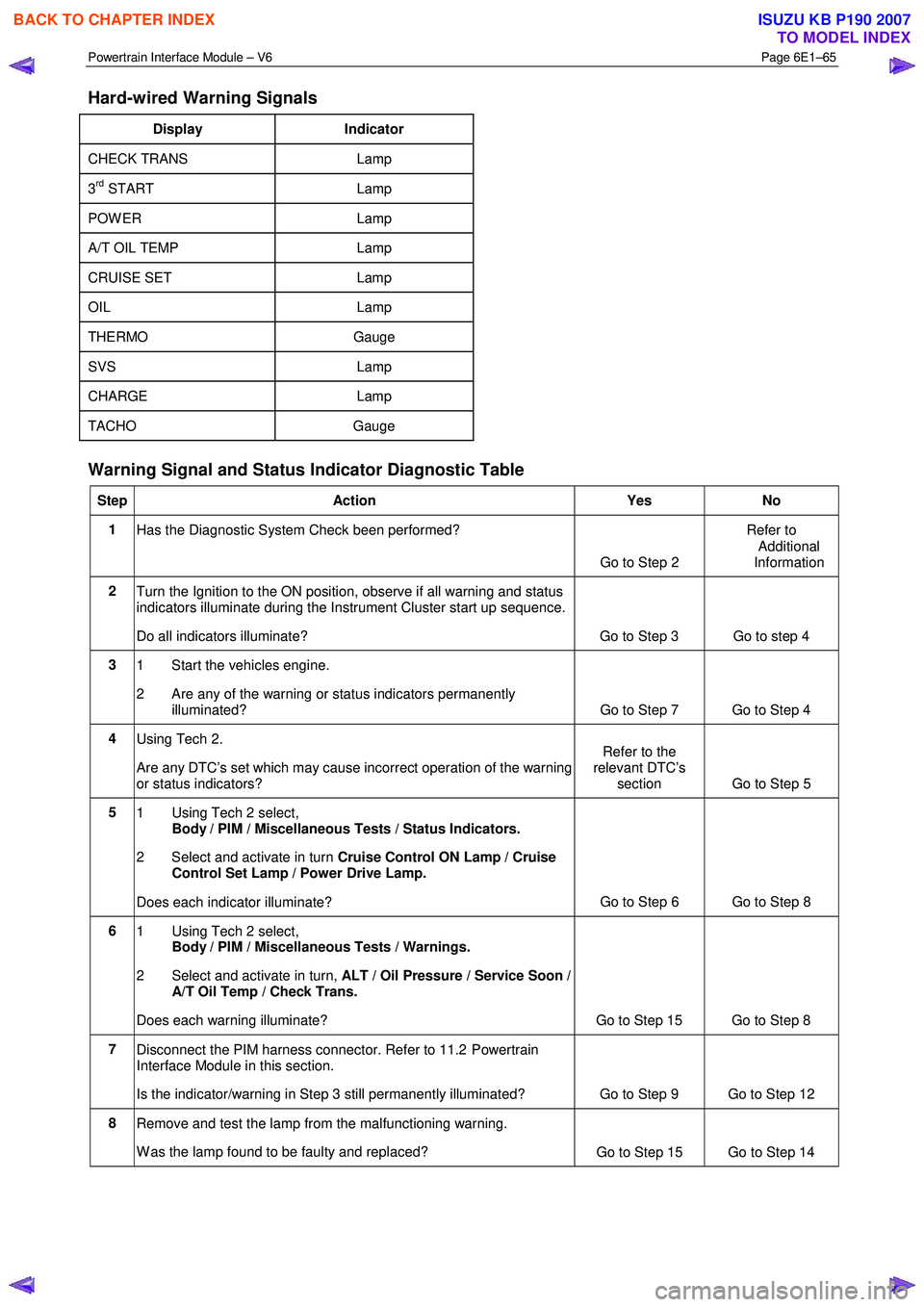
Hard-wired Warning Signals
Display Indicator
CHECK TRANS Lamp
3rd START Lamp
POW ER Lamp
A/T OIL TEMP Lamp
CRUISE SET Lamp
OIL Lamp
THERMO Gauge
SVS Lamp
CHARGE Lamp
TACHO Gauge
Warning Signal and Status Indicator Diagnostic Table
Step Action Yes No
1
Has the Diagnostic System Check been performed?
Go to Step 2 Refer to
Additional
Information
2 Turn the Ignition to the ON position, observe if all warning and status
indicators illuminate during the Instrument Cluster start up sequence.
Do all indicators illuminate? Go to Step 3 Go to step 4
3 1 Start the vehicles engine.
2 Are any of the warning or status indicators permanently illuminated? Go to Step 7 Go to Step 4
4 Using Tech 2.
Are any DTC’s set which may cause incorrect operation of the warning
or status indicators? Refer to the
relevant DTC’s section Go to Step 5
5
1 Using Tech 2 select,
Body / PIM / Miscellaneous Tests / Status Indicators.
2 Select and activate in turn Cruise Control ON Lamp / Cruise
Control Set Lamp / Power Drive Lamp.
Does each indicator illuminate? Go to Step 6 Go to Step 8
6
1 Using Tech 2 select,
Body / PIM / Miscellaneous Tests / Warnings.
2 Select and activate in turn, ALT / Oil Pressure / Service Soon /
A/T Oil Temp / Check Trans.
Does each warning illuminate? Go to Step 15 Go to Step 8
7 Disconnect the PIM harness connector. Refer to 11.2 Powertrain
Interface Module in this section.
Is the indicator/warning in Step 3 still permanently illuminated? Go to Step 9 Go to Step 12
8 Remove and test the lamp from the malfunctioning warning.
W as the lamp found to be faulty and replaced? Go to Step 15 Go to Step 14
BACK TO CHAPTER INDEX
TO MODEL INDEX
ISUZU KB P190 2007
Page 3727 of 6020
Powertrain Interface Module – V6 Page 6E1–66
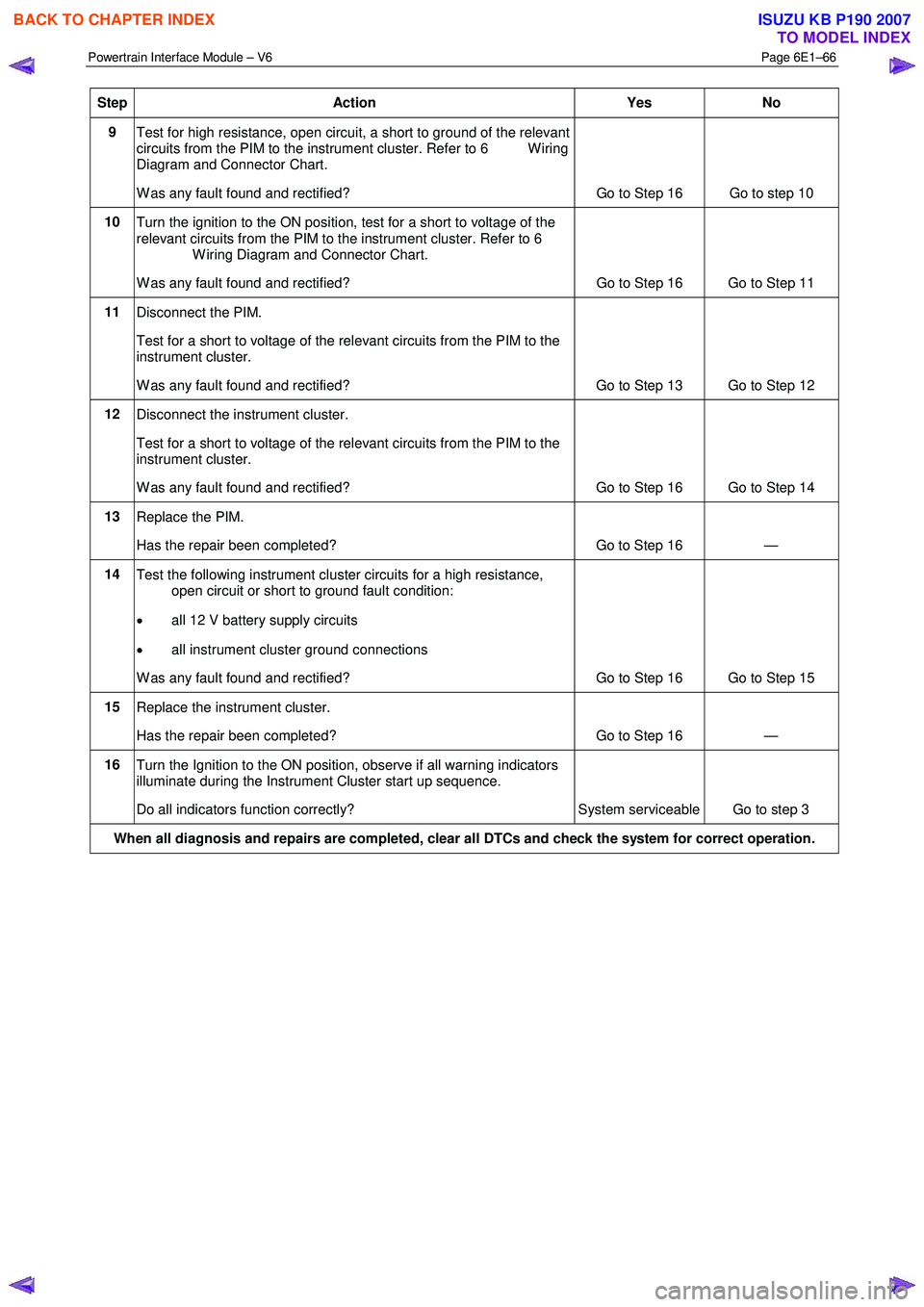
Step Action Yes No
9
Test for high resistance, open circuit, a short to ground of the relevant
circuits from the PIM to the instrument cluster. Refer to 6 W iring
Diagram and Connector Chart.
W as any fault found and rectified? Go to Step 16 Go to step 10
10
Turn the ignition to the ON position, test for a short to voltage of the
relevant circuits from the PIM to the instrument cluster. Refer to 6
W iring Diagram and Connector Chart.
W as any fault found and rectified? Go to Step 16 Go to Step 11
11
Disconnect the PIM.
Test for a short to voltage of the relevant circuits from the PIM to the
instrument cluster.
W as any fault found and rectified? Go to Step 13 Go to Step 12
12 Disconnect the instrument cluster.
Test for a short to voltage of the relevant circuits from the PIM to the
instrument cluster.
W as any fault found and rectified? Go to Step 16 Go to Step 14
13 Replace the PIM.
Has the repair been completed? Go to Step 16 —
14 Test the following instrument cluster circuits for a high resistance,
open circuit or short to ground fault condition:
• all 12 V battery supply circuits
• all instrument cluster ground connections
W as any fault found and rectified? Go to Step 16 Go to Step 15
15 Replace the instrument cluster.
Has the repair been completed? Go to Step 16 —
16 Turn the Ignition to the ON position, observe if all warning indicators
illuminate during the Instrument Cluster start up sequence.
Do all indicators function correctly? System serviceable Go to step 3
When all diagnosis and repairs are completed, clear all DTCs and check the system for correct operation.
BACK TO CHAPTER INDEX
TO MODEL INDEX
ISUZU KB P190 2007
Page 3743 of 6020
Powertrain Interface Module – V6 Page 6E1–82
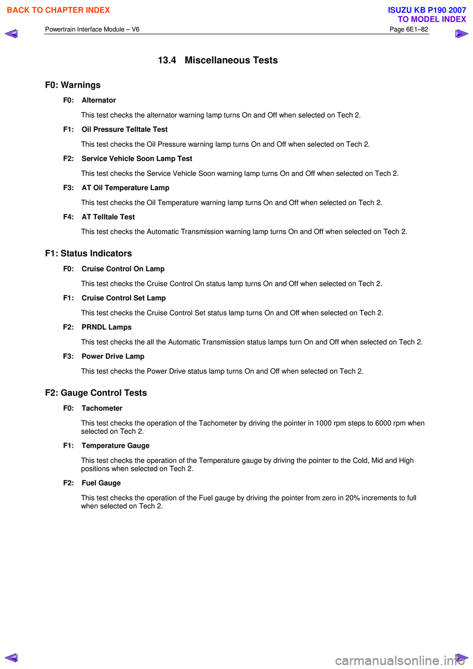
13.4 Miscellaneous Tests
F0: Warnings
F0: Alternator
This test checks the alternator warning lamp turns On and Off when selected on Tech 2.
F1: Oil Pressure Telltale Test
This test checks the Oil Pressure warning lamp turns On and Off when selected on Tech 2.
F2: Service Vehicle Soon Lamp Test
This test checks the Service Vehicle Soon warning lamp turns On and Off when selected on Tech 2.
F3: AT Oil Temperature Lamp
This test checks the Oil Temperature warning lamp turns On and Off when selected on Tech 2.
F4: AT Telltale Test
This test checks the Automatic Transmission warning lamp turns On and Off when selected on Tech 2.
F1: Status Indicators
F0: Cruise Control On Lamp
This test checks the Cruise Control On status lamp turns On and Off when selected on Tech 2.
F1: Cruise Control Set Lamp
This test checks the Cruise Control Set status lamp turns On and Off when selected on Tech 2.
F2: PRNDL Lamps
This test checks the all the Automatic Transmission status lamps turn On and Off when selected on Tech 2.
F3: Power Drive Lamp
This test checks the Power Drive status lamp turns On and Off when selected on Tech 2.
F2: Gauge Control Tests
F0: Tachometer
This test checks the operation of the Tachometer by driving the pointer in 1000 rpm steps to 6000 rpm when
selected on Tech 2.
F1: Temperature Gauge
This test checks the operation of the Temperature gauge by driving the pointer to the Cold, Mid and High
positions when selected on Tech 2.
F2: Fuel Gauge
This test checks the operation of the Fuel gauge by driving the pointer from zero in 20% increments to full when selected on Tech 2.
BACK TO CHAPTER INDEX
TO MODEL INDEX
ISUZU KB P190 2007
Page 3787 of 6020

Automatic Transmission – 4L60E – Electrical Diagnosis Page 7C2–1
7C2
Diagnosis
ATTENTION
Before performing any service operation or other procedure described in this Section, refer to 00 Warnings, Cautions and Notes for correct workshop practices with regard to safety and/or property damage.
1 General Information ............................................................................................................ ...................8
1.1 Introduction ............................................................................................................................................................ 8
1.2 General Description ............................................................................................................................................... 8
Transmission Adaptive Functions ................................................................................................ ....................... 9
Limp Home Mode Description ............................................................................................................................ 10
1.3 Transmission Indicators and Messages ............................................................................................................ 10
1.4 Electronic Component Description ............................................................................................... ..................... 10
Transmission Control Module (TCM) ................................................................................................................. 10
2 Wiring Diagrams and Connector Chart ............................................................................................ ..13
3 Tech 2 Information ...............................................................................................................................14
3.1 Tech 2 Diagnostics .............................................................................................................................................. 14
Test Modes ........................................................................................................................................................... 14
Diagnostic Trouble Codes ....................................................................................................... ......................... 14
Data Display ..................................................................................................................................................... 14
Snapshot .......................................................................................................................................................... 15
Additional Functions ........................................................................................................... .............................. 15
Miscellaneous Tests ......................................................................................................................................... 15
Programming.................................................................................................................................................... 16
3.2 Data Display ......................................................................................................................................................... 16
Transmission Data .............................................................................................................. ................................. 16
Transmission Data Parameters ................................................................................................... ..................... 16
TCC Data............................................................................................................................................................... 17
TCC Data Parameters ............................................................................................................ .......................... 17
1-2 Shift Data ........................................................................................................................................................ 18
1-2 Shift Data Parameters ................................................................................................................................ 18
2-3 Shift Data ........................................................................................................................................................ 18
2-3 Shift Data Parameters ................................................................................................................................ 18
3-4 Shift Data ........................................................................................................................................................ 19
3-4 Shift Data Parameters ................................................................................................................................ 19
3-2 Downshift Data............................................................................................................................................... 19
3-2 Downshift Data Parameters ....................................................................................................................... 19
Pressure Control Solenoid Data ................................................................................................. ........................ 19
Pressure Control Solenoid Data Parameters ...................................................................................... ............. 20
Transmission Adapts .......................................................................................................................................... 20
1-2 Adapt Data ................................................................................................................................................. 20
2-3 Adapt Data ................................................................................................................................................. 20
3-4 Adapt Data ................................................................................................................................................. 20
Steady State Adapt Data ........................................................................................................ .......................... 21
3.3 Tech 2 Data Definitions ........................................................................................................ ............................... 21
3.4 Miscellaneous Tests ............................................................................................................................................ 23
Automatic Tra nsm ission – 4L60E – Electric al
BACK TO CHAPTER INDEX
TO MODEL INDEX
ISUZU KB P190 2007
Page 3822 of 6020
Automatic Transmission – 4L60E – Electrical Diagnosis Page 7C2–36
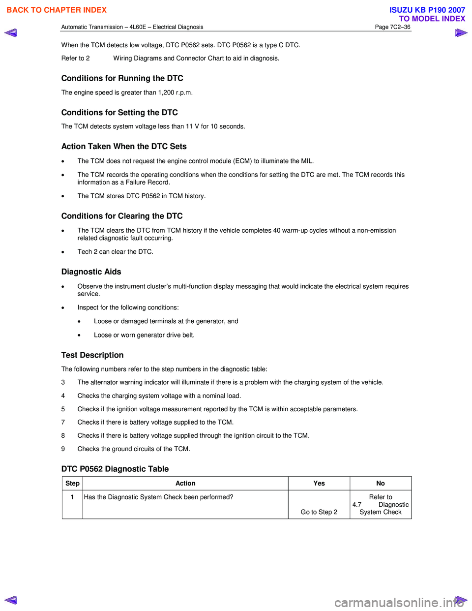
When the TCM detects low voltage, DTC P0562 sets. DTC P0562 is a type C DTC.
Refer to 2 W iring Diagrams and Connector Chart to aid in diagnosis.
Conditions for Running the DTC
The engine speed is greater than 1,200 r.p.m.
Conditions for Setting the DTC
The TCM detects system voltage less than 11 V for 10 seconds.
Action Taken When the DTC Sets
• The TCM does not request the engine control module (ECM) to illuminate the MIL.
• The TCM records the operating conditions when the conditions for setting the DTC are met. The TCM records this
information as a Failure Record.
• The TCM stores DTC P0562 in TCM history.
Conditions for Clearing the DTC
• The TCM clears the DTC from TCM history if the vehicle completes 40 warm-up cycles without a non-emission
related diagnostic fault occurring.
• Tech 2 can clear the DTC.
Diagnostic Aids
• Observe the instrument cluster’s multi-function display messaging that would indicate the electrical system requires
service.
• Inspect for the following conditions:
• Loose or damaged terminals at the generator, and
• Loose or worn generator drive belt.
Test Description
The following numbers refer to the step numbers in the diagnostic table:
3 The alternator warning indicator will illuminate if there is a problem with the charging system of the vehicle.
4 Checks the charging system voltage with a nominal load.
5 Checks if the ignition voltage measurement reported by the TCM is within acceptable parameters.
7 Checks if there is battery voltage supplied to the TCM.
8 Checks if there is battery voltage supplied through the ignition circuit to the TCM.
9 Checks the ground circuits of the TCM.
DTC P0562 Diagnostic Table
Step Action Yes No
1 Has the Diagnostic System Check been performed?
Go to Step 2 Refer to
4.7 Diagnostic
System Check
BACK TO CHAPTER INDEX
TO MODEL INDEX
ISUZU KB P190 2007
Page 3823 of 6020
Automatic Transmission – 4L60E – Electrical Diagnosis Page 7C2–37
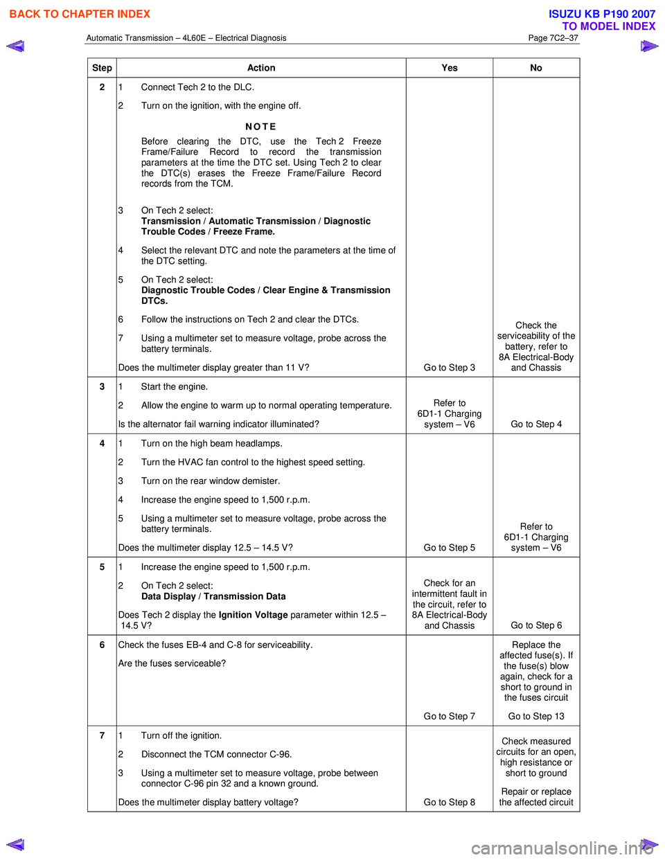
Step Action Yes No
2 1 Connect Tech 2 to the DLC.
2 Turn on the ignition, with the engine off.
NOTE
Before clearing the DTC, use the Tech 2 Freeze
Frame/Failure Record to record the transmission
parameters at the time the DTC set. Using Tech 2 to clear
the DTC(s) erases the Freeze Frame/Failure Record
records from the TCM.
3 On Tech 2 select: Transmission / Automatic Transmission / Diagnostic
Trouble Codes / Freeze Frame.
4 Select the relevant DTC and note the parameters at the time of the DTC setting.
5 On Tech 2 select:
Diagnostic Trouble Codes / Clear Engine & Transmission
DTCs.
6 Follow the instructions on Tech 2 and clear the DTCs.
7 Using a multimeter set to measure voltage, probe across the battery terminals.
Does the multimeter display greater than 11 V? Go to Step 3 Check the
serviceability of the battery, refer to
8A Electrical-Body and Chassis
3 1 Start the engine.
2 Allow the engine to warm up to normal operating temperature.
Is the alternator fail warning indicator illuminated? Refer to
6D1-1 Charging system – V6 Go to Step 4
4 1 Turn on the high beam headlamps.
2 Turn the HVAC fan control to the highest speed setting.
3 Turn on the rear window demister.
4 Increase the engine speed to 1,500 r.p.m.
5 Using a multimeter set to measure voltage, probe across the battery terminals.
Does the multimeter display 12.5 – 14.5 V? Go to Step 5 Refer to
6D1-1 Charging system – V6
5 1 Increase the engine speed to 1,500 r.p.m.
2 On Tech 2 select: Data Display / Transmission Data
Does Tech 2 display the Ignition Voltage parameter within 12.5 –
14.5 V? Check for an
intermittent fault in the circuit, refer to
8A Electrical-Body
and Chassis Go to Step 6
6
Check the fuses EB-4 and C-8 for serviceability.
Are the fuses serviceable?
Go to Step 7 Replace the
affected fuse(s). If the fuse(s) blow
again, check for a short to ground in the fuses circuit
Go to Step 13
7 1 Turn off the ignition.
2 Disconnect the TCM connector C-96.
3 Using a multimeter set to measure voltage, probe between connector C-96 pin 32 and a known ground.
Does the multimeter display battery voltage? Go to Step 8 Check measured
circuits for an open,
high resistance or short to ground
Repair or replace
the affected circuit
BACK TO CHAPTER INDEX
TO MODEL INDEX
ISUZU KB P190 2007
Page 3825 of 6020

Automatic Transmission – 4L60E – Electrical Diagnosis Page 7C2–39
Conditions for Setting the DTC
The TCM detects system voltage greater than 18 V for 10 seconds.
Action Taken When the DTC Sets
•
The TCM does not request the engine control module (ECM) to illuminate the MIL.
• The TCM records the operating conditions when the conditions for setting the DTC are met. The TCM records this
information as a Failure Record.
• The TCM stores DTC P0563 in TCM history.
Conditions for Clearing the DTC
•
The TCM clears the DTC from TCM history if the vehicle completes 40 warm-up cycles without a non-emission
related diagnostic fault occurring.
• Tech 2 can clear the DTC.
Diagnostic Aids
• Observe the instrument cluster’s multi-function display for messaging that would indicate the electrical system
requires service.
• Use Tech 2 to inspect all other modules for voltage related DTCs.
• Running the engine with a battery charger attached may cause DTC P0563 to set.
• Inspect the charging circuit for high resistance.
• Inspect the vehicle battery for open or sulphated cells.
Test Description
The following numbers refer to the step numbers in the diagnostic table:
3 The alternator warning indicator will illuminate if there is a problem with the charging system of the vehicle.
4 Checks the charging system voltage with a minimal load.
5 Checks if there is a difference between the Tech 2 reading and the voltage measure in an earlier step.
DTC P0563 Diagnostic Table
Step Action Yes No
1 Has the Diagnostic System Check been performed?
Go to Step 2 Refer to
4.7 Diagnostic System Check
BACK TO CHAPTER INDEX
TO MODEL INDEX
ISUZU KB P190 2007
Page 3967 of 6020

TRANSMISSION CONTROL SYSTEM (AW30–40LE) 7A2-1
SECTION 7A2
TRANSMISSION CONTROL SYSTEM (AW30–40LE)
TABLE OF CONTENTS
Service Precaution ................................................. 7A2-2
General Description ............................................... 7A2-2
Components Location ........................................ 7A2-3
Operating Condition ........................................... 7A2-4
Electronic Control Diagram ...............................7A2-5
Transmission Control Module (TCM) (1/2) .....7A2-6
Transmission Control Module (TCM) (2/2) .....7A2-7
TCM Point Table ................................................. 7A2-8
TCM Voltage & Resistance Check Sheet .......7A2-9
Control System Diagram ...................................7A2-11
Control and Functions ........................................ 7A2-12
Functions of Input / Output Components ........7A2-15
CAN bus systems in automatic transmission
control (AW 30-40LE) ........................................ 7A2-16
High speed CAN bus .......................................... 7A2-16
Diagnosis ................................................................ 7A2-16
Electronic Diagnosis ........................................... 7A2-16
Check Trans Indicator ........................................ 7A2-16
On-Board Diagnostic (OBD) System Check ...7A2-17
“Check Trans” Check ......................................... 7A2-17
Tech 2 Operating ................................................ 7A2-20
Snapshot Display W ith TIS2000 ................... 7A2-26
Service Programming System (SPS) ............. 7A2-30
OBD Diagnostic Management System ............7A2-33
16 - Terminal Data Link Connector (DLC) ......7A2-34
Clear DTC ............................................................ 7A2-35
DTC Check .......................................................... 7A2-35
Self-diagnosis code (Flash code) display ........7A2-35
TCM Precaution .................................................. 7A2-36
Information On TCM .......................................... 7A2-36
TCM Diagnostic Trouble Codes .......................7A2-38
Diagnostic Trouble Code (DTC) Type
Definitions ........................................................... 7A2-39
DTC P0562 or P0563 (Flash Code 72 or 73) .....7A2-40
DTC P0602 (Flash Code 63) ............................. 7A2-43
DTC P0707 or P0708 (Flash Code 17) ............. 7A2-45
DTC P0712 (Flash Code 15) ............................. 7A2-49
DTC P0713 (Flash Code 16) ............................. 7A2-52
DTC P0717 (Flash Code 14) ............................. 7A2-55
DTC P0722 (Flash Code 11) ............................. 7A2-59
DTC P0741 (Flash Code 43) ............................. 7A2-63
DTC P0742 (Flash Code 53) ............................. 7A2-67
DTC P0746 (Flash Code 45) ............................. 7A2-71
DTC P0751 (Flash Code 41)..............................7A2-74
DTC P0752 (Flash Code 51)..............................7A2-78
DTC P0756 (Flash Code 42)..............................7A2-82
DTC P0757 (Flash Code 52)..............................7A2-86
DTC P0962 or P0963 (Flash Code 35) ..............7A2-90
DTC P0973 or P0974 (Flash Code 31) ..............7A2-93
DTC P0976 or P0977 (Flash Code 32) ..............7A2-97
DTC P1790 (Flash Code 61)..............................7A2-101
DTC P1791 (Flash Code 62)..............................7A2-103
DTC P2769 or P2770 (Flash Code 33) ..............7A2-105
DTC P2773 or 2774 (Flash Code 75) ................7A2-109
DTC U2104 (Flash Code 65) .............................7A2-112
DTC U2105 (Flash Code 67) .............................7A2-116
BACK TO CHAPTER INDEX
TO MODEL INDEX
ISUZU KB P190 2007
Page 4110 of 6020
ON-VEHICLE SERVICE (AW30–40LE) 7A3-25
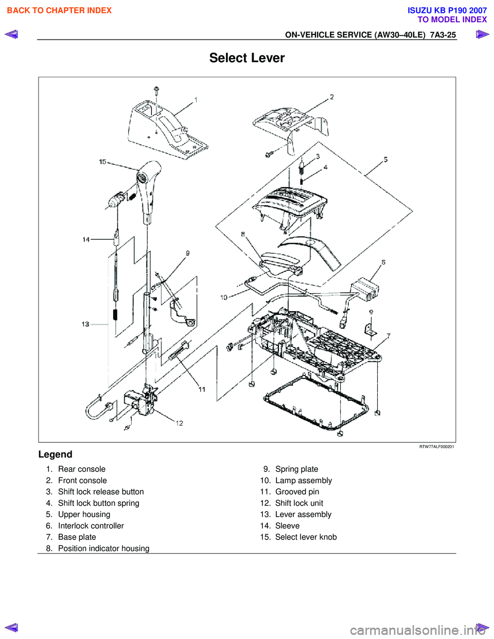
Select Lever
RTW 77ALF000201
Legend
1. Rear console
2. Front console
3. Shift lock release button
4. Shift lock button spring 5. Upper housing
6. Interlock controller
7. Base plate
8. Position indicator housing
9. Spring plate
10. Lamp assembly
11. Grooved pin
12. Shift lock unit
13. Lever assembly
14. Sleeve
15. Select lever knob
BACK TO CHAPTER INDEX
TO MODEL INDEX
ISUZU KB P190 2007
Page 4111 of 6020
7A3-26 ON-VEHICLE SERVICE (AW30–40LE)
Remove or Disconnect
1. Block the wheels.
2. Disconnect the negative battery cable.
3. Remove the rear console and the front console.
4. Remove the 2 screws fixing the select lever knob.
5. Remove the knob together with the knob button and spring from the lever.
6. Turn the sleeve counterclockwise to remove it. Make a note of the number of turns required to free
the sleeve.
7. Remove the harness connectors from the base plate.
8. Remove the upper housing (held in place by 4 latched fasteners).
9. Remove the lamp assembly by turning it counterclockwise.
10. Remove the spring plate.
11. Remove the grooved pin.
12. Disconnect the shift cable from the select lever.
13. Remove the lever assembly by pressing the rod down (lever in N position).
14. Remove the harness connectors from the shift lock unit, then remove the shift lock unit.
15. Remove the interlock controller.
16. If the replacement of shift lock release button o
r
shift lock button spring is required, remove the
position indicator housing, the shift lock button
spring and shift lock release button can be
removed.
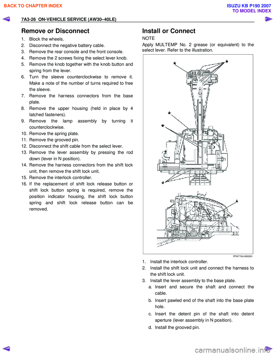
Install or Connect
NOTE
Apply MULTEMP No. 2 grease (or equivalent) to the
select lever. Refer to the illustration.
RTW 77ALH000201
1. Install the interlock controller.
2. Install the shift lock unit and connect the harness to the shift lock unit.
3. Install the lever assembly to the base plate. a. Insert and secure the shaft and connect the cable.
b. Insert pawled end of the shaft into the base plate hole.
c. Insert the detent pin of the shaft into detent aperture (lever assembly in N position).
d. Install the grooved pin.
BACK TO CHAPTER INDEX
TO MODEL INDEX
ISUZU KB P190 2007