jacking points ISUZU KB P190 2007 Workshop Repair Manual
[x] Cancel search | Manufacturer: ISUZU, Model Year: 2007, Model line: KB P190, Model: ISUZU KB P190 2007Pages: 6020, PDF Size: 70.23 MB
Page 3182 of 6020
Engine Cooling – V6 Engine Page 6B1–47
Disconnection of the battery affects certain
vehicle electronic systems. Refer to 1.1
WARNING, CAUTION and NOTES, before
removing the ground lead.
2 Disconnect the battery ground lead. Refer to 8A – Electrical Body & Chassis.
Refer to ‘
‘‘
‘
Environmental Issues ’
’’
’
in 3.1
Service Notes, before draining the coolant.
3 Draining the coolant from the system. Refer to 3.3 Draining and Filling Cooling System in this Section.
4 Raise the front of the vehicle and support on safety stands. Refer to 0A General Information for the location of jacking and support points.
Always wear protective safety glasses when
working with spring type hose clamps.
Failure to do so could result in eye injury.
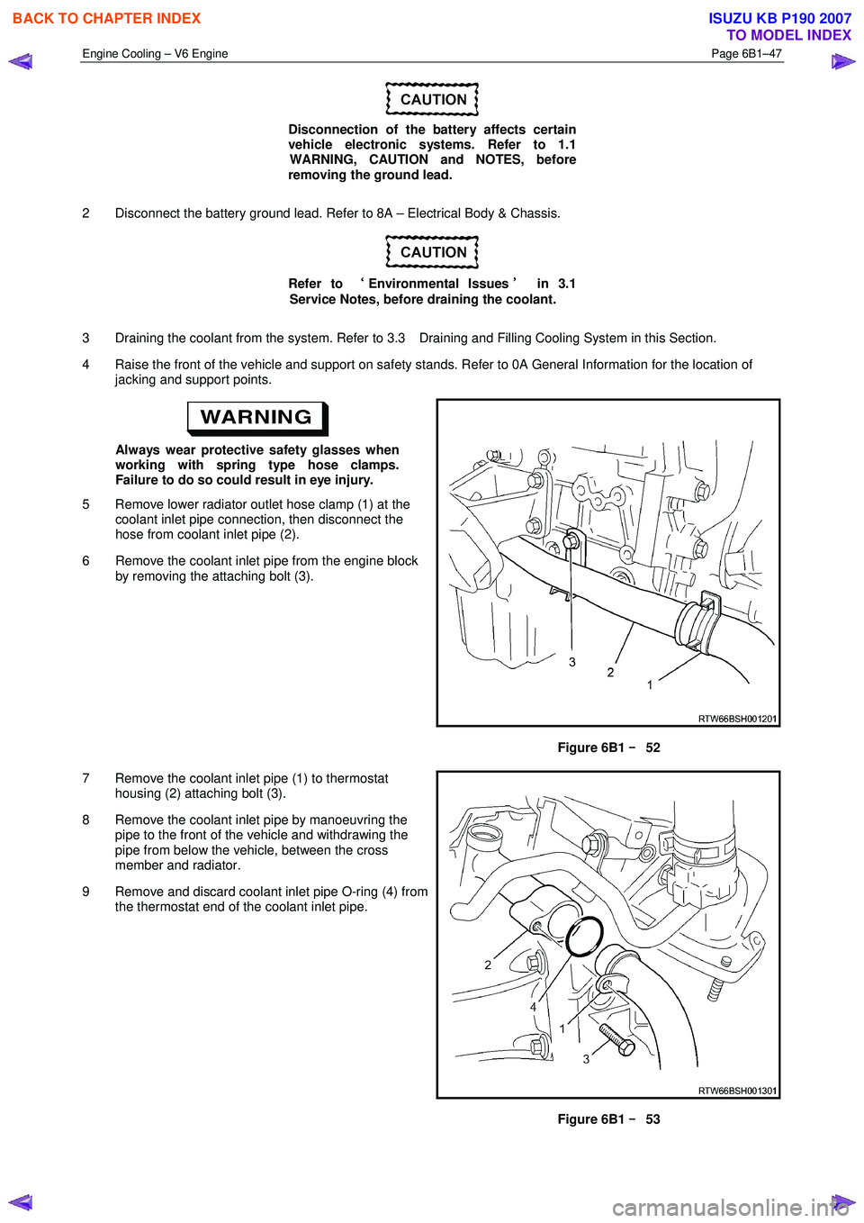
5 Remove lower radiator outlet hose clamp (1) at the coolant inlet pipe connection, then disconnect the
hose from coolant inlet pipe (2).
6 Remove the coolant inlet pipe from the engine block by removing the attaching bolt (3).
Figure 6B1 –
––
–
52
7 Remove the coolant inlet pipe (1) to thermostat housing (2) attaching bolt (3).
8 Remove the coolant inlet pipe by manoeuvring the pipe to the front of the vehicle and withdrawing the
pipe from below the vehicle, between the cross
member and radiator.
9 Remove and discard coolant inlet pipe O-ring (4) from the thermostat end of the coolant inlet pipe.
Figure 6B1 –
––
–
53
BACK TO CHAPTER INDEX
TO MODEL INDEX
ISUZU KB P190 2007
Page 3183 of 6020
Engine Cooling – V6 Engine Page 6B1–48
Install
1 Ensure that the coolant inlet pipe and thermostat housing mating surfaces are clean and dry.
2 Install new O-ring to the coolant inlet pipe.
3 Install coolant inlet pipe at the thermostat housing and secure with the attaching bolt. Tighten all bolts to the correct torque specification.
Coolant inlet pipe to thermostat
housing bolt torque specification ..........................23 N.m
4 Raise the front of the vehicle and support on safety stands. Refer to 0A General Information for the location of jacking and support points.
5 Reinstall the coolant inlet pipe to the engine block and secure with the bolt tightened to the correct torque specification.
Coolant inlet pipe to engine block bolt
torque specification .............................................25 N.m
Always wear protective safety glasses when
working with spring type hose clamps. Failure
to do so could result in eye injury.
6 Connect the lower radiator outlet hose and clamp to the coolant inlet pipe connection.
7 Close the radiator drain tap on the lower RHS of the radiator and remove the piece of rubber tubing to the tap outlet.
8 Lower the front of the vehicle.
9 Refill cooling system. Refer to 3.3 Draining and Filling Cooling System in this Section.
10 Check for coolant leaks. Refer to 3.7 Pressure Testing in this Section.
11 Reconnect battery ground lead. Refer to 8A – Electrical Body & Chassis.
3.13 Cooling Fan and Shroud Assembly
Remove
Disconnection of the battery affects certain
vehicle electronic systems. Refer to 1.1
WARNING, CAUTION and NOTES, before
removing the ground lead.
1 Disconnect the battery ground lead. Refer to 8A – Electrical Body & Chassis.
2 Remove the intake duct and mass air flow as an assembly. Refer to 6A1 Engine Mechanical.
3 Remove the coolant recovery hose from the fan shroud retaining clip.
BACK TO CHAPTER INDEX
TO MODEL INDEX
ISUZU KB P190 2007
Page 3410 of 6020
Engine Management – V6 – Diagnostics Page 6C1-2–132
Step Action Yes No
7
To avoid damage to the drive axles, support the lower
control arms in the normal horizontal position. Do not
run the vehicle in gear with the wheels hanging down
at full travel.
1 Raise the vehicle and support the drive axles with safety stands. Refer to 0A General Information for the location of jacking and
support points.
2 Connect a fused jumper wire between the ground circuit of the connector and the ground circuit of the VSS.
3 Connect a fused jumper wire between the ignition circuit of the connector and the ignition circuit of the VSS.
4 Using connector test adaptor kit J 35616-A, connect a digital multimeter between the VSS signal circuit and ground.
5 Place the transmission in neutral.
6 Rotate the rear wheels by hand while observing the multimeter.
Does the multimeter indicate greater than 0.15 V AC? Go to Step 10 Go to Step 8
8 Perform the following VSS inspection:
• Inspect the VSS wiring harness for conditions that may induce
electromagnetic interference. Refer to 5.2 Intermittent Fault
Conditions in this Section.
• Inspect the VSS for incorrect installation or incorrect attaching
bolt torque value. Refer to 6C1-3 Engine Management – V6 –
Service Operations.
• Inspect the VSS sensor reluctor wheel for damage or conditions
that causes misalignment.
W as any fault found and rectified? Go to Step 12 Go to Step 9
9 Replace the VSS. Refer to 7B1 Manual Transmission – V6.
W as the repair completed? Go to Step 12 —
10 Test the VSS signal circuit for a high resistance, open circuit, short to
ground or short to voltage fault condition. Refer to 8A Electrical -
Body and Chassis for information on electrical fault diagnosis.
W as any fault found and rectified? Go to Step 12 Go to Step 11
11 Replace the ECM. Refer to 6C1-3 Engine Management – V6 –
Service Operations.
W as the repair completed? Go to Step 12 —
12 1 Using Tech 2, clear the DTCs.
2 Switch off the ignition for 30 seconds.
3 Start the engine.
4 Operate the vehicle within the conditions for running the DTC.
Does DTC P0500 fail this ignition cycle? Go to Step 2 Go to Step 13
BACK TO CHAPTER INDEX
TO MODEL INDEX
ISUZU KB P190 2007
Page 3537 of 6020
Engine Management – V6 – Service Operations Page 6C1-3–13
Clean the area around the CMP sensor before
removal to avoid debris from entering the
engine.
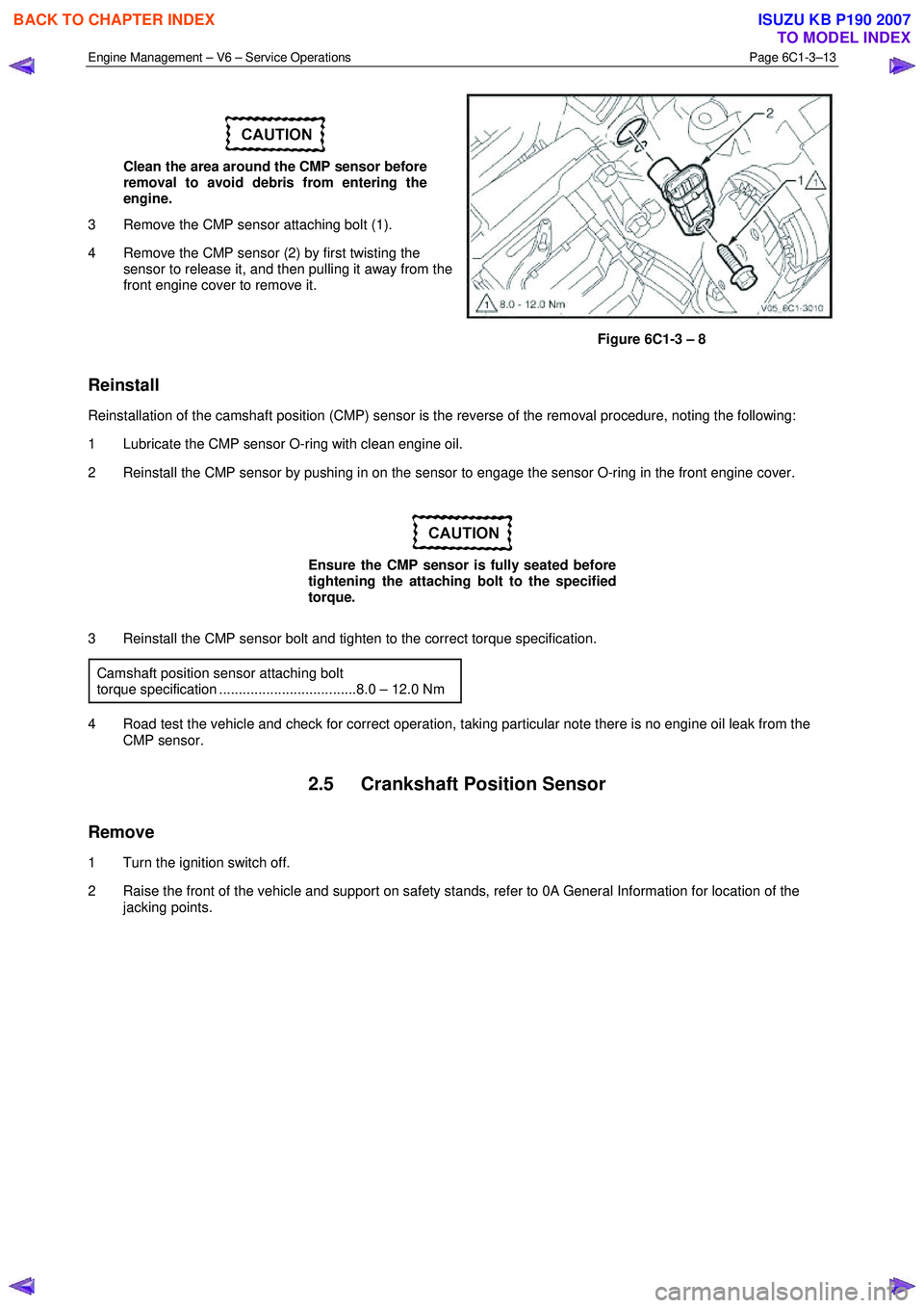
3 Remove the CMP sensor attaching bolt (1).
4 Remove the CMP sensor (2) by first twisting the sensor to release it, and then pulling it away from the
front engine cover to remove it.
Figure 6C1-3 – 8
Reinstall
Reinstallation of the camshaft position (CMP) sensor is the reverse of the removal procedure, noting the following:
1 Lubricate the CMP sensor O-ring with clean engine oil.
2 Reinstall the CMP sensor by pushing in on the sensor to engage the sensor O-ring in the front engine cover.
Ensure the CMP sensor is fully seated before
tightening the attaching bolt to the specified
torque.
3 Reinstall the CMP sensor bolt and tighten to the correct torque specification. Camshaft position sensor attaching bolt
torque specification ...................................8.0 – 12.0 Nm
4 Road test the vehicle and check for correct operation, taking particular note there is no engine oil leak from the CMP sensor.
2.5 Crankshaft Position Sensor
Remove
1 Turn the ignition switch off.
2 Raise the front of the vehicle and support on safety stands, refer to 0A General Information for location of the jacking points.
BACK TO CHAPTER INDEX
TO MODEL INDEX
ISUZU KB P190 2007
Page 3546 of 6020
Engine Management – V6 – Service Operations Page 6C1-3–22
3 Road test the vehicle and check for correct operation.
2.9 Engine Oil Level and Temperature
Sensor
To avoid personal injury, take care when
draining the engine oil or removing the engine
oil level and temperature sensor whilst the
engine is hot. Allow the engine to cool before
performing this procedure.
Remove
1 Turn the ignition switch off.
2 Raise the front and rear of the vehicle and support on safety stands, refer to 0A General Information for location of the jacking points.
3 Drain the engine oil, refer to 6A1 Engine Mechanical – V6.
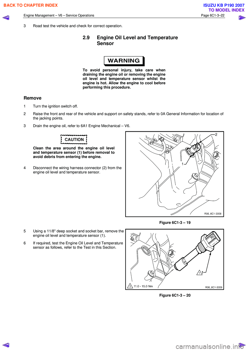
Clean the area around the engine oil level
and temperature sensor (1) before removal to
avoid debris from entering the engine.
4 Disconnect the wiring harness connector (2) from the engine oil level and temperature sensor.
Figure 6C1-3 – 19
5 Using a 11/8" deep socket and socket bar, remove the engine oil level and temperature sensor (1).
6 If required, test the Engine Oil Level and Temperature sensor as follows, refer to the Test in this Section.
Figure 6C1-3 – 20
BACK TO CHAPTER INDEX
TO MODEL INDEX
ISUZU KB P190 2007
Page 3558 of 6020
Engine Management – V6 – Service Operations Page 6C1-3–34
• If the HO2S has been removed, but not replaced, anti-seize compound must be applied to the threads prior to
installation. New HO2S will already have the anti-seize compound applied.
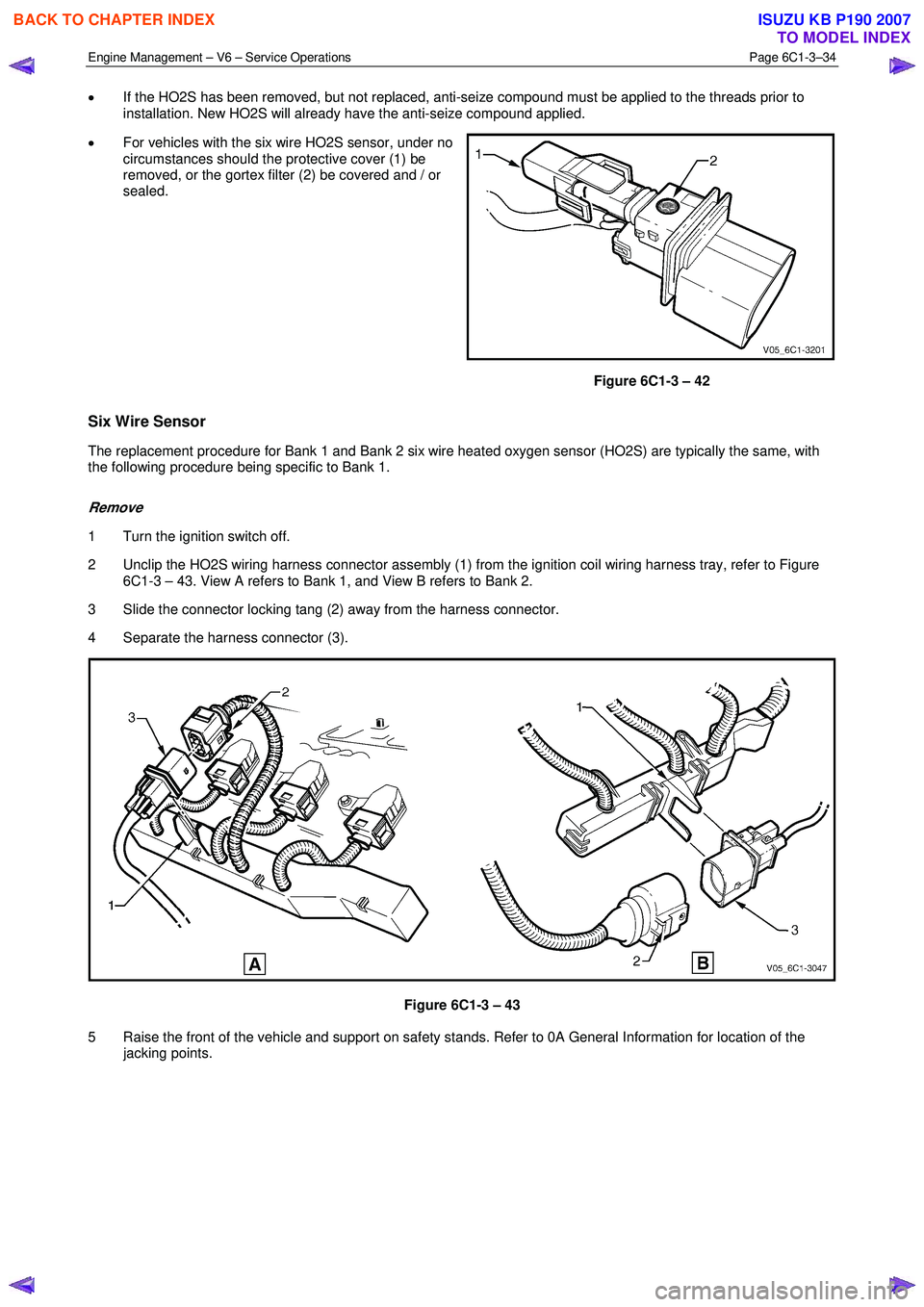
• For vehicles with the six wire HO2S sensor, under no
circumstances should the protective cover (1) be
removed, or the gortex filter (2) be covered and / or
sealed.
Figure 6C1-3 – 42
Six Wire Sensor
The replacement procedure for Bank 1 and Bank 2 six wire heated oxygen sensor (HO2S) are typically the same, with
the following procedure being specific to Bank 1.
Remove
1 Turn the ignition switch off.
2 Unclip the HO2S wiring harness connector assembly (1) from the ignition coil wiring harness tray, refer to Figure 6C1-3 – 43. View A refers to Bank 1, and View B refers to Bank 2.
3 Slide the connector locking tang (2) away from the harness connector.
4 Separate the harness connector (3).
Figure 6C1-3 – 43
5 Raise the front of the vehicle and support on safety stands. Refer to 0A General Information for location of the jacking points.
BACK TO CHAPTER INDEX
TO MODEL INDEX
ISUZU KB P190 2007
Page 3560 of 6020
Engine Management – V6 – Service Operations Page 6C1-3–36
Remove
1 Turn the ignition switch off.
2 Raise the vehicle and support on safety stands, refer to 0A General Information for location of the jacking points.
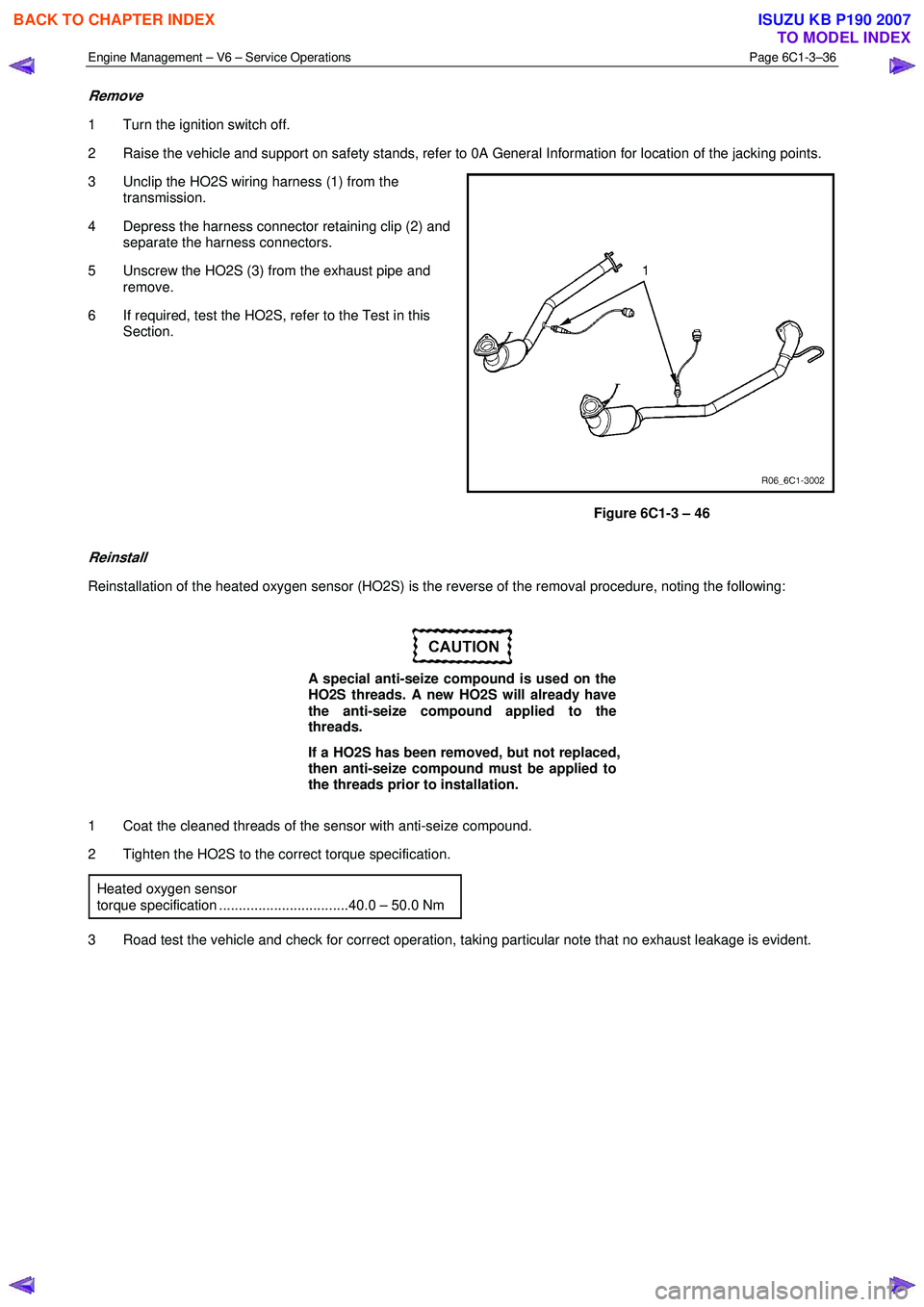
3 Unclip the HO2S wiring harness (1) from the transmission.
4 Depress the harness connector retaining clip (2) and separate the harness connectors.
5 Unscrew the HO2S (3) from the exhaust pipe and remove.
6 If required, test the HO2S, refer to the Test in this Section.
Figure 6C1-3 – 46
Reinstall
Reinstallation of the heated oxygen sensor (HO2S) is the reverse of the removal procedure, noting the following:
A special anti-seize compound is used on the
HO2S threads. A new HO2S will already have
the anti-seize compound applied to the
threads.
If a HO2S has been removed, but not replaced,
then anti-seize compound must be applied to
the threads prior to installation.
1 Coat the cleaned threads of the sensor with anti-seize compound.
2 Tighten the HO2S to the correct torque specification.
Heated oxygen sensor
torque specification .................................40.0 – 50.0 Nm
3 Road test the vehicle and check for correct operation, taking particular note that no exhaust leakage is evident.
BACK TO CHAPTER INDEX
TO MODEL INDEX
ISUZU KB P190 2007
Page 3566 of 6020
Engine Management – V6 – Service Operations Page 6C1-3–42
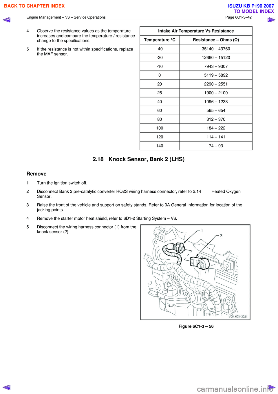
4 Observe the resistance values as the temperature
increases and compare the temperature / resistance
change to the specifications.
5 If the resistance is not within specifications, replace the MAF sensor.
Intake Air Temperature Vs Resistance
Temperature °C Resistance – Ohms (
Ω)
-40 35140 – 43760
-20 12660 – 15120
-10 7943 – 9307
0 5119 – 5892
20 2290 – 2551
25 1900 – 2100
40 1096 – 1238
60 565 – 654
80 312 – 370
100 184 – 222
120 114 – 141
140 74 – 93
2.18 Knock Sensor, Bank 2 (LHS)
Remove
1 Turn the ignition switch off.
2 Disconnect Bank 2 pre-catalytic converter HO2S wiring harness connector, refer to 2.14 Heated Oxygen Sensor.
3 Raise the front of the vehicle and support on safety stands. Refer to 0A General Information for location of the jacking points.
4 Remove the starter motor heat shield, refer to 6D1-2 Starting System – V6.
5 Disconnect the wiring harness connector (1) from the knock sensor (2).
Figure 6C1-3 – 56
BACK TO CHAPTER INDEX
TO MODEL INDEX
ISUZU KB P190 2007
Page 3567 of 6020
Engine Management – V6 – Service Operations Page 6C1-3–43
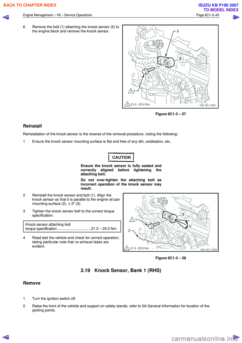
6 Remove the bolt (1) attaching the knock sensor (2) to
the engine block and remove the knock sensor.
Figure 6C1-3 – 57
Reinstall
Reinstallation of the knock sensor is the reverse of the removal procedure, noting the following:
1 Ensure the knock sensor mounting surface is flat and free of any dirt, oxidisation, etc.
Ensure the knock sensor is fully seated and
correctly aligned before tightening the
attaching bolt.
Do not over-tighten the attaching bolt as
incorrect operation of the knock sensor may
result.
2 Reinstall the knock sensor and bolt (1). Align the knock sensor so that it is parallel to the engine oil pan
mounting surface (2), ± 3° (3).
3 Tighten the knock sensor bolt to the correct torque specification.
Knock sensor attaching bolt
torque specification .................................21.0 – 25.0 Nm
4 Road test the vehicle and check for correct operation, taking particular note that no exhaust leaks are
evident.
Figure 6C1-3 – 58
2.19 Knock Sensor, Bank 1 (RHS)
Remove
1 Turn the ignition switch off.
2 Raise the front of the vehicle and support on safety stands, refer to 0A General Information for location of the jacking points.
BACK TO CHAPTER INDEX
TO MODEL INDEX
ISUZU KB P190 2007