service indicator ISUZU KB P190 2007 Workshop Service Manual
[x] Cancel search | Manufacturer: ISUZU, Model Year: 2007, Model line: KB P190, Model: ISUZU KB P190 2007Pages: 6020, PDF Size: 70.23 MB
Page 3438 of 6020
Engine Management – V6 – Diagnostics Page 6C1-2–160
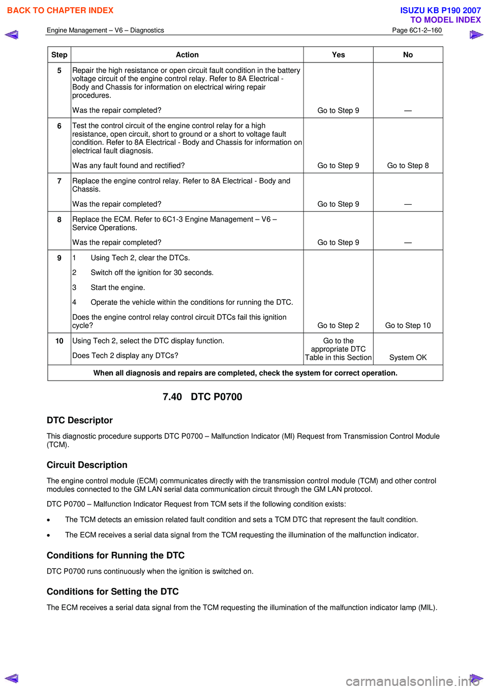
Step Action Yes
No
5 Repair the high resistance or open circuit fault condition in the battery
voltage circuit of the engine control relay. Refer to 8A Electrical -
Body and Chassis for information on electrical wiring repair
procedures.
W as the repair completed? Go to Step 9 —
6 Test the control circuit of the engine control relay for a high
resistance, open circuit, short to ground or a short to voltage fault
condition. Refer to 8A Electrical - Body and Chassis for information on
electrical fault diagnosis.
W as any fault found and rectified? Go to Step 9 Go to Step 8
7 Replace the engine control relay. Refer to 8A Electrical - Body and
Chassis.
W as the repair completed? Go to Step 9 —
8 Replace the ECM. Refer to 6C1-3 Engine Management – V6 –
Service Operations.
W as the repair completed? Go to Step 9 —
9 1 Using Tech 2, clear the DTCs.
2 Switch off the ignition for 30 seconds.
3 Start the engine.
4 Operate the vehicle within the conditions for running the DTC.
Does the engine control relay control circuit DTCs fail this ignition
cycle? Go to Step 2 Go to Step 10
10 Using Tech 2, select the DTC display function.
Does Tech 2 display any DTCs? Go to the
appropriate DTC
Table in this Section System OK
When all diagnosis and repairs are completed, check the system for correct operation.
7.40 DTC P0700
DTC Descriptor
This diagnostic procedure supports DTC P0700 – Malfunction Indicator (MI) Request from Transmission Control Module
(TCM).
Circuit Description
The engine control module (ECM) communicates directly with the transmission control module (TCM) and other control
modules connected to the GM LAN serial data communication circuit through the GM LAN protocol.
DTC P0700 – Malfunction Indicator Request from TCM sets if the following condition exists:
• The TCM detects an emission related fault condition and sets a TCM DTC that represent the fault condition.
• The ECM receives a serial data signal from the TCM requesting the illumination of the malfunction indicator.
Conditions for Running the DTC
DTC P0700 runs continuously when the ignition is switched on.
Conditions for Setting the DTC
The ECM receives a serial data signal from the TCM requesting the illumination of the malfunction indicator lamp (MIL).
BACK TO CHAPTER INDEX
TO MODEL INDEX
ISUZU KB P190 2007
Page 3443 of 6020

Engine Management – V6 – Diagnostics Page 6C1-2–165
Step Action Yes
No
10 1 Using Tech 2, clear the DTCs.
2 Switch off the ignition for 30 seconds.
3 Start the engine.
4 Operate the vehicle within the conditions for running the DTC.
Does DTC P0850 fail this ignition cycle? Go to Step 2 Go to Step 11
11 Using Tech 2, select the DTC display function.
Does Tech 2 display any DTCs? Go to the
appropriate DTC
Table in this Section System OK
When all diagnosis and repairs are completed, check the system for correct operation.
7.43 DTC P1648
DTC Descriptor
This diagnostic procedure supports DTC P1648 – W rong Security Code Entered.
Circuit Description
Tech 2 is used to program the engine control module (ECM). Before any programming, a security code must be entered
into Tech 2. The ECM will check if the code entered is correct before continuing. If the security code is incorrect, DTC
P1648 sets.
Conditions for Running the DTC
Conditions for running the DTC are:
• The ignition is switched on.
• The ignition voltage is 10.0 – 16.0 V.
Conditions for Setting the DTC
An incorrect security code is entered into Tech 2 when attempting to program the ECM.
Action Taken When the DTC Sets
W hen the DTC sets, the malfunction indicator lamp (MIL) is not displayed.
Conditions for Clearing the DTC
The immobiliser security code is a Type ‘C’ DTC. Refer to 1.4 Diagnostic Trouble Codes in this Section, for action
taken when a Type ‘C’ DTC sets and conditions for clearing Type ‘C’ DTCs.
Additional Information
• Refer to 6C1-1 Engine Management –V6 – General Information for details of the ECM operation.
• Refer to 6C1-3 Engine Management –V6 – Service Operations for details on resetting the ECM.
• Since fault condition in a wiring connector may trigger DTCs, always test the connectors related to this diagnostic
procedure for shorted terminals or poor wiring connection before replacing any component. Refer to 8A Electrical -
Body and Chassis for information on electrical fault diagnosis.
• For an intermittent fault condition, refer to 5.2 Intermittent Fault Conditions in this Section.
• To assist diagnosis, refer to 3 W iring Diagrams and Connector Charts in this Section, for the system wiring
diagram and connector charts.
BACK TO CHAPTER INDEX
TO MODEL INDEX
ISUZU KB P190 2007
Page 3632 of 6020
Starting System – V6 Page 6D1-2–24
No Load Test
1 Clamp the starter motor securely to a test bench.
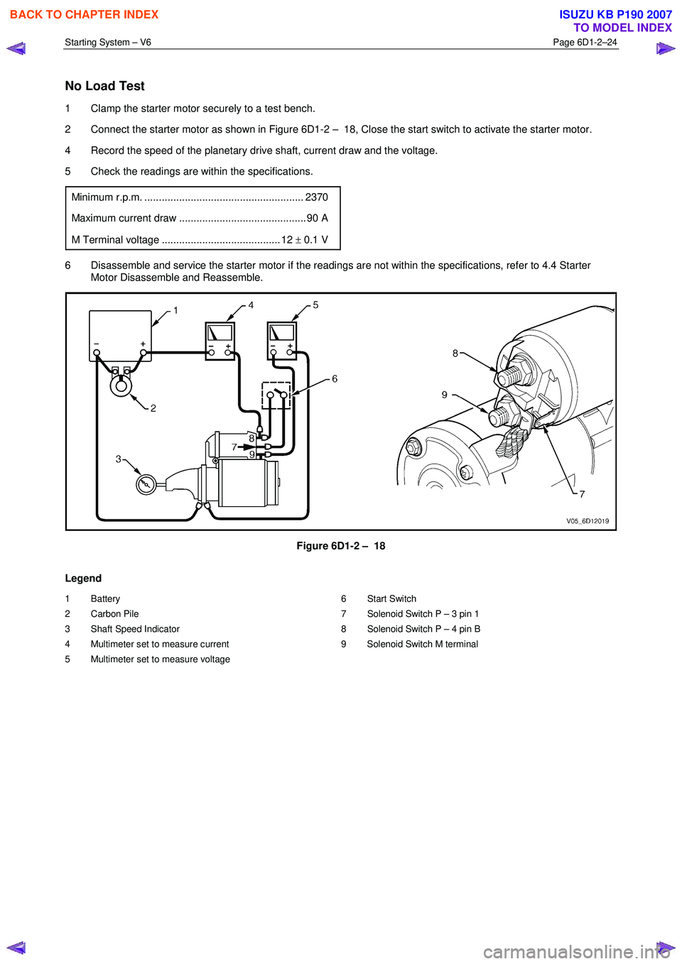
2 Connect the starter motor as shown in Figure 6D1-2 – 18, Close the start switch to activate the starter motor.
4 Record the speed of the planetary drive shaft, current draw and the voltage.
5 Check the readings are within the specifications.
Minimum r.p.m. ....................................................... 2370
Maximum current draw ............................................ 90 A
M Terminal voltage ......................................... 12 ± 0.1 V
6 Disassemble and service the starter motor if the readings are not within the specifications, refer to 4.4 Starter
Motor Disassemble and Reassemble.
Figure 6D1-2 – 18
Legend
1 Battery
2 Carbon Pile
3 Shaft Speed Indicator
4 Multimeter set to measure current
5 Multimeter set to measure voltage 6 Start Switch
7 Solenoid Switch P – 3 pin 1
8 Solenoid Switch P – 4 pin B
9 Solenoid Switch M terminal
BACK TO CHAPTER INDEX
TO MODEL INDEX
ISUZU KB P190 2007
Page 3665 of 6020

Powertrain Interface Module – V6 Page 6E1–4
Conditions for Setting the DTC........................................................................................................................... 56
Conditions for Clearing the DTC ................................................................................................ ........................ 56
Additional Information......................................................................................................................................... 56
DTC P0633 Diagnostic Table..................................................................................................... .......................... 56
9.15 DTC P1611 – Wrong Security Code Entered........................................................................................ .............. 57
DTC Description ................................................................................................................................................... 57
Circuit Description ............................................................................................................................................... 57
Additional Information......................................................................................................... ................................ 57
Conditions for Running the DTC ................................................................................................. ....................... 58
Conditions for Setting the DTC........................................................................................................................... 58
Action Taken When the DTC Sets ................................................................................................. ..................... 58
Conditions for Clearing the DTC ........................................................................................................................ 58
Test Description ................................................................................................................................................... 58
DTC P1611 Diagnostic Table..................................................................................................... .......................... 58
9.16 DTC B0981 – 3rd Start Switch Signal Malfunction ............................................................................................. 59
DTC Description ................................................................................................................................................... 59
Circuit Description ............................................................................................................................................... 59
Additional Information......................................................................................................... ................................ 59
Conditions for Running the DTC ................................................................................................. ....................... 59
Conditions for Setting the DTC........................................................................................................................... 60
Action Taken When the DTC Sets ................................................................................................. ..................... 60
Conditions for Clearing the DTC ........................................................................................................................ 60
Test Description ................................................................................................................................................... 60
DTC B0980 Diagnostic Table ..................................................................................................... ......................... 60
10 Diagnostics For Non DTC Faults ................................................................................................. .......62
10.1 PRND32L Display Diagnostics ............................................................................................... ................................ 62
Circuit Description ............................................................................................................................................... 62
Additional Information......................................................................................................... ................................ 62
Test Description ................................................................................................................................................... 62
PRND32L Display Diagnostic Table ............................................................................................... .................... 63
10.2 Warning Signal and Status Indicators Diagnostics.......................................................................... .................... 64
Circuit Description ............................................................................................................................................... 64
Additional Information......................................................................................................... ................................ 64
Test Description ................................................................................................................................................... 64
Hard-wired Warning Signals ..................................................................................................... .......................... 65
Warning Signal and Status Indicator Diagnostic Table ........................................................................... ......... 65
10.3 Tachometer Diagnostics......................................................................................................................................... 67
Circuit Description ............................................................................................................................................... 67
Additional Information......................................................................................................... ................................ 67
Test Description ................................................................................................................................................... 67
Tachometer Diagnostic Table .................................................................................................... ......................... 67
10.4 Temperature Gauge Diagnostics ............................................................................................. .............................. 69
Circuit Description ............................................................................................................................................... 69
Additional Information......................................................................................................... ................................ 69
Test Description ................................................................................................................................................... 69
Temperature Gauge Diagnostic Table ............................................................................................. .................. 70
11 Service Operations ...............................................................................................................................71
11.1 Safety and Precautionary Measures .................................................................................................................. 71
11.2 Powertrain Interface Module ............................................................................................................................... 71
Remove ................................................................................................................................................................. 72
Reinstall ................................................................................................................................................................ 72
11.3 Vertical Acceleration Sensor ................................................................................................... ........................... 73
Remove ................................................................................................................................................................. 73
Reinstall ................................................................................................................................................................ 73
12 PIM Security and Programming ................................................................................................... .......74
BACK TO CHAPTER INDEX
TO MODEL INDEX
ISUZU KB P190 2007
Page 3692 of 6020
Powertrain Interface Module – V6 Page 6E1–31
9 DTC Tables
9.1 DTC C0550 – PIM Internal Fault
DTC Description
This diagnostic procedure supports the following DTCs:
• DTC C0550 – EEPROM Error.
• DTC C0550 – Internal Control Module Read Only Memory (ROM Error).
• DTC C0550 – Internal Control Module Random Access Memory (RAM) Error.
Circuit Description
The powertrain interface module (PIM) is the control centre for the communication language conversion between GM
LAN serial data and keyword 2000 serial data. If there is an internal microprocessor integrity fault condition with the PIM,
DTC C0550 will set.
Additional Information
• Refer to 6 W iring Diagram and Connector Chart for the following information:
• PIM connector illustration and terminal assignment, and
• PIM wiring diagram.
• For intermittent fault conditions, refer to Intermittent Fault Conditions.
• Since fault conditions in a wiring connector may trigger DTCs, always test the connectors related to this diagnostic
procedure for shorted terminals or poor wiring connection before replacing any component. Refer to 8A Electrical -
Body and Chassis for information on electrical fault diagnosis.
Conditions for Running the DTC
• Conditions for running the DTC are:
• The ignition is switched on.
• The ignition voltage is 10.0 – 16.0 V.
Conditions for Setting the DTC
An internal PIM fault exists.
Action Taken When the DTC Sets
The action taken when any of these DTCs set will depend on the severity of the error. This may vary from no visual or
audible warnings to a Malfunction Indicator Lamp and / or Service Vehicle Soon warning lamp displayed on the
instrument cluster.
Conditions for Clearing the DTC
Refer to 4.1 Diagnostic General Descriptions for information on the conditions for clearing DTCs.
Test Description
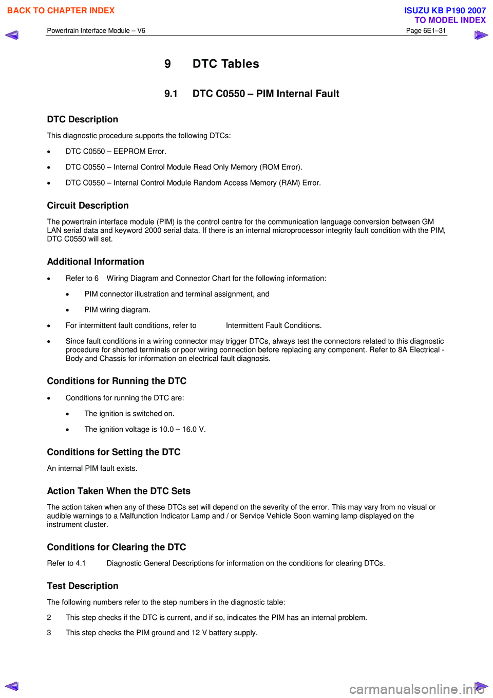
The following numbers refer to the step numbers in the diagnostic table:
2 This step checks if the DTC is current, and if so, indicates the PIM has an internal problem.
3 This step checks the PIM ground and 12 V battery supply.
BACK TO CHAPTER INDEX
TO MODEL INDEX
ISUZU KB P190 2007
Page 3694 of 6020
Powertrain Interface Module – V6 Page 6E1–33
• PIM connector illustration and terminal assignment, and
• PIM wiring diagram.
• For intermittent fault conditions, refer to Intermittent Fault Conditions.
• Since fault conditions in a wiring connector may trigger DTCs, always test the connectors related to this diagnostic
procedure for shorted terminals or poor wiring connection before replacing any component. Refer to 8A Electrical -
Body and Chassis for information on electrical fault diagnosis.
Conditions for Running the DTC
Conditions for running the DTC are:
• The ignition is switched on.
• The ignition voltage is 10.0 – 16.0 V.
Conditions for Setting the DTC
The PIM detects a short to ground or short to voltage on the GM LAN circuits when the ignition is switched on and the
short condition exists for greater than five seconds.
NOTE
This DTC will only set when the ignition has
initially been turned to the ON position, and will
not set when the vehicle is being driven.
Action Taken When the DTC Sets
• W hen the DTC sets, the following warning lamps are displayed on the instrument cluster:
• Malfunction Indicator Lamp, and
• Service Vehicle Soon.
Conditions for Clearing the DTC
Refer to 4.1 Diagnostic General Descriptions for information on the conditions for clearing DTCs.
Test Description
The following numbers refer to the step numbers in the diagnostic table:
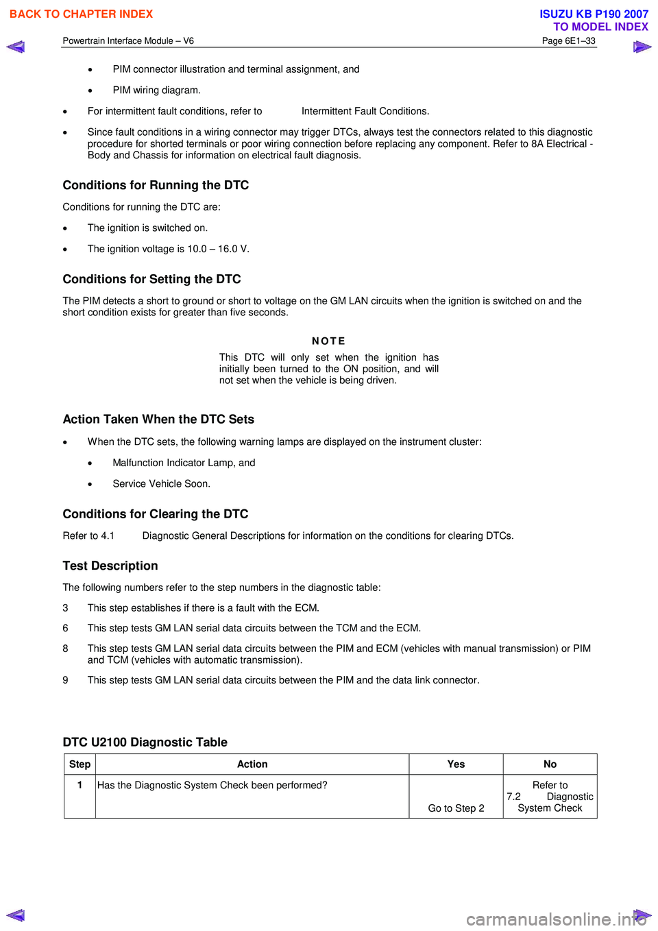
3 This step establishes if there is a fault with the ECM.
6 This step tests GM LAN serial data circuits between the TCM and the ECM.
8 This step tests GM LAN serial data circuits between the PIM and ECM (vehicles with manual transmission) or PIM and TCM (vehicles with automatic transmission).
9 This step tests GM LAN serial data circuits between the PIM and the data link connector.
DTC U2100 Diagnostic Table
Step Action Yes No
1
Has the Diagnostic System Check been performed?
Go to Step 2 Refer to
7.2 Diagnostic System Check
BACK TO CHAPTER INDEX
TO MODEL INDEX
ISUZU KB P190 2007
Page 3697 of 6020

Powertrain Interface Module – V6 Page 6E1–36
• Malfunction Indicator Lamp,
• Service Vehicle Soon
Conditions for Clearing the DTC
Refer to 4.1 Diagnostic General Descriptions for information on the conditions for clearing DTCs.
Test Description
The following numbers refer to the step numbers in the diagnostic table:
4 This step tests GM LAN serial data circuits and the GM LAN component closest to the ECM.
5 This step tests the integrity of the ECM 12 V ignition circuit and ground connections.
6 This step tests the internal GM LAN CAN_HI circuit in the GM LAN component.
7 This step tests the internal GM LAN CAN_LO circuit in the GM LAN component.
DTC U2105 Diagnostic Table
Step Action Yes No
1
Has the Diagnostic System Check been performed?
Go to Step 2 Refer to
7.2 Diagnostic
System Check
2 1 Switch off the ignition for 10 seconds.
2 Operate the vehicle within the conditions for setting DTC U2105.
3 Using Tech 2, select the DTC display function.
Does DTC U2105 fail this ignition cycle? Go to Step 3 Refer to
Additional
Information in this
Section
3 Using Tech 2, attempt to communicate with the ECM.
Does Tech 2 communicate with the ECM? Go to Step 10 Go to Step 4
4 Test serial data circuits between the ECM and PIM (vehicles with
manual transmission), or ECM and TCM (vehicles with automatic
transmission) for a high resistance or open circuit fault condition.
Refer to 8A Electrical - Body and Chassis for information on wiring
circuit testing and repair.
Has any fault been found and rectified? Go to Step 11 Go to Step 5
5 Test the following ECM circuits for a high resistance, open circuit or
short to ground fault condition. Refer to 8A Electrical - Body and
Chassis for information on electrical diagnosis:
• 12 V battery supply circuit,
• 12 V accessory supply circuit, and
• all ECM ground connections.
Has any fault been found and rectified? Go to Step 11 Go to Step 6
BACK TO CHAPTER INDEX
TO MODEL INDEX
ISUZU KB P190 2007
Page 3699 of 6020
Powertrain Interface Module – V6 Page 6E1–38
9.4 DTC U2106 – CAN Bus No
Communication With Transmission
Control Module
DTC Description
This diagnostic procedure supports DTC U2106 – CAN Bus No Communication W ith TCM (Transmission Control
Module).
Circuit Description
The transmission control module (TCM) and engine control module (ECM) transmit and receive data using the GM LAN
serial data protocol, while the immobiliser control unit (ICU) uses Keyword 2000 serial data protocol.
As the GM LAN and keyword 2000 protocols are not compatible, a powertrain interface module (PIM) is integrated into
the serial data system to enable communication between the two different protocols. The PIM also integrates with the
instrument cluster assembly.
The PIM continuously receives messages from the TCM. If the PIM does not receive a message within a predetermined
time, DTC U2106 sets.
Additional Information
• Refer to 6 W iring Diagram and Connector for the following information:
• PIM connector illustration and terminal assignment, and
• PIM wiring diagram.
• For intermittent fault conditions, refer to Intermittent Fault Conditions.
• Since fault conditions in a wiring connector may trigger DTCs, always test the connectors related to this diagnostic
procedure for shorted terminals or poor wiring connection before replacing any component. Refer to 8A Electrical -
Body and Chassis for information on electrical fault diagnosis.
Conditions for Running the DTC
Conditions for running the DTC are:
• The ignition is switched on.
• The ignition voltage is 10.0 – 16.0 V.
Conditions for Setting the DTC
The PIM does not receive a message from the TCM for 1000 milliseconds, during the current ignition cycle.
Action Taken When the DTC Sets
• W hen the DTC sets, the following warning lamps may be displayed on the instrument cluster:
• Malfunction Indicator Lamp,
• Service Vehicle Soon.
Conditions for Clearing the DTC
Refer to 4.1 Diagnostic General Descriptions for information on the conditions for clearing DTCs.
Test Description
The following numbers refer to the step numbers in the diagnostic table:
4 This step tests the TCM power and ground circuits.
5 This step tests GM LAN serial data circuits between the TCM and the PIM.
BACK TO CHAPTER INDEX
TO MODEL INDEX
ISUZU KB P190 2007
Page 3723 of 6020

Powertrain Interface Module – V6 Page 6E1–62
10 Diagnostics For Non DTC Faults
10.1 PRND32L Display Diagnostics
Circuit Description
The powertrain interface module (PIM) receives transmission gear status via the GM Lan serial data bus from the
transmission control module (TCM) it is then sent to the instrument cluster by the PIM via a series of hard wired
connections to illuminate the appropriate gear position indicator within the instrument cluster. Some of these components
do not set a DTC, in the event of a component failure. The following diagnostic procedures are devised to assist in these
cases.
Additional Information
• Refer to 7.2 Diagnostic System Check to monitor DTC’s.
• Refer to 8A Electrical Body and Chassis for the following information:
• Automatic transmission Neutral Start and Back-up Lamp Switch and wiring,
• TCM wiring diagram.
• Refer to 6 W iring Diagram and Connector Chart for the following information:
• PIM connector illustration and terminal assignment, and
• PIM wiring diagram.
• For intermittent faults, refer to Intermittent Fault Conditions.
• Check for an intermittent fault in the wiring harness or connectors, if a fault cannot be found the system is
serviceable.
Since fault conditions in a wiring connector may trigger DTCs, always test the connectors related to this diagnostic
procedure for shorted terminals or poor wiring connection before replacing any component. Refer to 8A Electrical - Body
and Chassis for information on electrical fault diagnosis.
Test Description
The following numbers refer to the step numbers in the diagnostic table:
1 This step tests for DTC’s in the overall system.
2 This step manually tests the PRND32L display.
4 This step uses Tech 2 to drive each indicator on.
7 This step tests for shorts to voltage.
8 This step tests neutral start and back-up lamp switch and automatic transmission.
12 This step tests the instrument cluster circuits.
15 This step manually tests the PRND32L display.
BACK TO CHAPTER INDEX
TO MODEL INDEX
ISUZU KB P190 2007
Page 3725 of 6020

Powertrain Interface Module – V6 Page 6E1–64
Step Action Yes No
12
Test the following instrument cluster circuits for a high resistance,
open circuit or short to ground fault condition:
• all 12 V battery supply circuits
• all instrument cluster ground connections
W as any fault found and rectified? Go to Step 15 Go to Step 13
13 Replace the instrument cluster.
Has the repair been completed? Go to Step 15 —
14 Replace the PIM.
Has the repair been completed? Go to step 15 —
15 1 Turn the ignition to the ON position.
2 Move the gear select lever through each gear position and check the PRND32L display.
Does each indicator display an off to on condition? System OK Go to step 2
When all diagnosis and repairs are completed, clear all DTCs and check the system for correct operation.
10.2 Warning Signal and Status Indicators Diagnostics
Circuit Description
The powertrain interface module (PIM) is connected to the instrument cluster by a series of hard wired connections to
illuminate the appropriate warnings and indicators within the instrument cluster. Some of these components do not set a
DTC, in the event of a component failure. The following diagnostic procedures are devised to assist in these cases.
Additional Information
• Refer to 7.2 Diagnostic System Check to monitor DTC’s.
• Refer to 8A Electrical Body and Chassis for the following information:
• Automatic transmission PRND32L switch and wiring,
• TCM wiring diagram.
• Refer to 6 W iring Diagram and Connector Chart for the following information:
• PIM connector illustration and terminal assignment, and
• PIM wiring diagram.
• For intermittent faults, refer to Intermittent Fault Conditions.
• Check for an intermittent fault in the wiring harness or connectors, if a fault cannot be found the system is
serviceable.
Test Description
The following numbers refer to the step numbers in the diagnostic table:
1 This step tests for DTC’s in the overall system.
2 This step manually tests the warning indicators.
5 This step uses Tech 2 to drive each status indicator on.
6 This step uses Tech 2 to drive each warning indicator on.
9 This step tests the wiring harness between the PIM and the Instrument Cluster.
BACK TO CHAPTER INDEX
TO MODEL INDEX
ISUZU KB P190 2007