check engine ISUZU KB P190 2007 Workshop Repair Manual
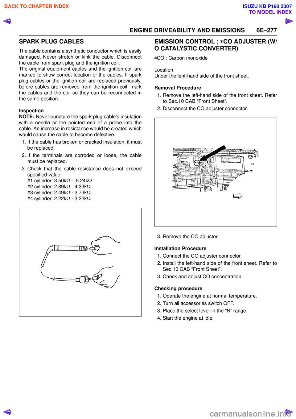
[x] Cancel search | Manufacturer: ISUZU, Model Year: 2007, Model line: KB P190, Model: ISUZU KB P190 2007Pages: 6020, PDF Size: 70.23 MB
Page 2436 of 6020

6E–266 ENGINE DRIVEABILITY AND EMISSIONS
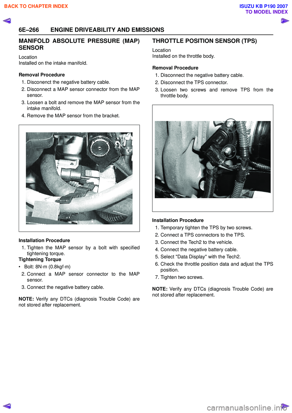
MANIFOLD ABSOLUTE PRESSURE (MAP)
SENSOR
Location
Installed on the intake manifold.
Removal Procedure 1. Disconenct the negative battery cable.
2. Disconnect a MAP sensor connector from the MAP sensor.
3. Loosen a bolt and remove the MAP sensor from the intake manifold.
4. Remove the MAP sensor from the bracket.
Installation Procedure 1. Tighten the MAP sensor by a bolt with specified tightening torque.
Tightening Torque
• Bolt: 8N·m (0.8kgf·m) 2. Connect a MAP sensor connector to the MAP sensor.
3. Connect the negative battery cable.
NOTE: Verify any DTCs (diagnosis Trouble Code) are
not stored after replacement.
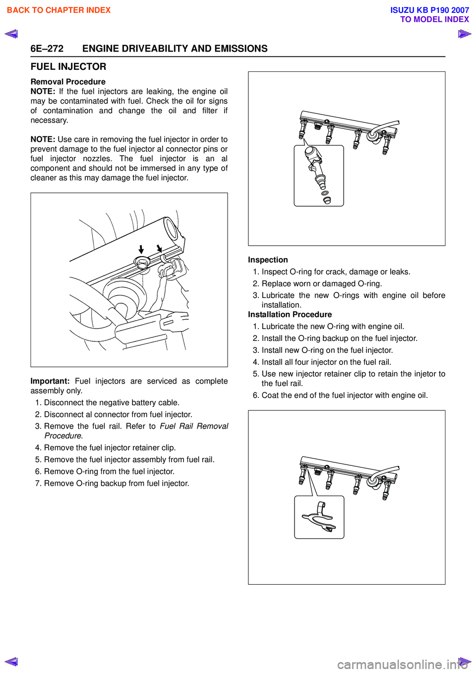
THROTTLE POSITION SENSOR (TPS)
Location
Installed on the throttle body.
Removal Procedure 1. Disconnect the negative battery cable.
2. Disconnect the TPS connector.
3. Loosen two screws and remove TPS from the throttle body.
Installation Procedure 1. Temporary tighten the TPS by two screws.
2. Connect a TPS connectors to the TPS.
3. Connect the Tech2 to the vehicle.
4. Connect the negative battery cable.
5. Select "Data Display" with the Tech2.
6. Check the throttle position data and adjust the TPS position.
7. Tighten two screws.
NOTE: Verify any DTCs (diagnosis Trouble Code) are
not stored after replacement.
BACK TO CHAPTER INDEX
TO MODEL INDEX
ISUZU KB P190 2007
Page 2441 of 6020

ENGINE DRIVEABILITY AND EMISSIONS 6E–271
8. If removal of fuel injector is necessary, Refer to Fuel
Injectors Removal Procedure .
Installation Procedure 1. Install the fuel injectors if necessary. Refer to Fuel Injector Installation Procedure.
2. Install the fuel pressure regulator if necessary. Refer to Fuel Pressure Regulator Installation Procedure .
3. Place the fuel injector rail assembly on the manifold and insert the injectors into each port by pushing
fuel rail.
4. Install two fuel rail retaining bolts. Tighten fuel rail retaining bolt to 19 N·m (1.9kgf·m)
5. Place wiring harness in its place and secure it with two nuts.
6. Connect all connector to each fuel injector.
7. Connect the fuel supply line securely. Do not over tighten. 8. Connect the fuel return line securely. Do not over
tighten.
9. Connect the negative battery cable.
10. Crank the engine until it starts. Cranking the engine may take longer than usual due to trapped air in the
fuel system. Check for leak. If fuel leak is observed,
stop engine immediately. Before correcting fuel
leak, be sure to depressurize system again.
BACK TO CHAPTER INDEX
TO MODEL INDEX
ISUZU KB P190 2007
Page 2442 of 6020

6E–272 ENGINE DRIVEABILITY AND EMISSIONS
FUEL INJECTOR
Removal Procedure
NOTE: If the fuel injectors are leaking, the engine oil
may be contaminated with fuel. Check the oil for signs
of contamination and change the oil and filter if
necessary.
NOTE: Use care in removing the fuel injector in order to
prevent damage to the fuel injector al connector pins or
fuel injector nozzles. The fuel injector is an al
component and should not be immersed in any type of
cleaner as this may damage the fuel injector.
Important: Fuel injectors are serviced as complete
assembly only.
1. Disconnect the negative battery cable.
2. Disconnect al connector from fuel injector.
3. Remove the fuel rail. Refer to Fuel Rail Removal
Procedure .
4. Remove the fuel injector retainer clip.
5. Remove the fuel injector assembly from fuel rail.
6. Remove O-ring from the fuel injector.
7. Remove O-ring backup from fuel injector. Inspection
1. Inspect O-ring for crack, damage or leaks.
2. Replace worn or damaged O-ring.
3. Lubricate the new O-rings with engine oil before installation.
Installation Procedure
1. Lubricate the new O-ring with engine oil.
2. Install the O-ring backup on the fuel injector.
3. Install new O-ring on the fuel injector.
4. Install all four injector on the fuel rail.
5. Use new injector retainer clip to retain the injetor to the fuel rail.
6. Coat the end of the fuel injector with engine oil.
BACK TO CHAPTER INDEX
TO MODEL INDEX
ISUZU KB P190 2007
Page 2445 of 6020

ENGINE DRIVEABILITY AND EMISSIONS 6E–275
IGNITION COIL
Location
Back of the engine right-hand side.
Removal Procedure 1. Disconnect the negative battery cable.
2. Disconnect the ignition coil connector.
3. Disconnect four spark plug cables from the ignition coil.
4. Loosen three bolts and remove ignition coil from the bracket.
Installation Procedure 1. Tighten the ignition coil by three bolts.
2. Connect four spark plug cables to the ignition coil.
3. Connect a ignition coil connector to the ignition coil.
4. Connect the negative battery cable.
NOTE: Verify any DTCs (diagnosis Trouble Code) are
not stored after replacement.
Verify proper connection of spark plug cables for each
cylinders.
SPARK PLUGS
Location
Installed on the left-hand side of cylinder head.
Removal Procedure 1. Disconnect the negative battery cable
2. Remove the spark plug cable.
3. Remove the spark plug.
Inspection 1. Check the insulator for cracks. Replace the spark plug if cracks are present.
2. Check the electrode condition and replace the spark plug if necessary.
If the spark plug electrodes and insulators are fouled
with carbon or oil, the engine will not operate efficiently.
There are a number of possible causes:
• Fuel mixture is too rich.
BACK TO CHAPTER INDEX
TO MODEL INDEX
ISUZU KB P190 2007
Page 2446 of 6020

6E–276 ENGINE DRIVEABILITY AND EMISSIONS
• Oil in the combustion chamber.
• The spark plug gap is not set correctly.
If spark plug fouling is excessive, check the fuel and al
system for possible causes of trouble. If fuel and al
system are normal, install spark plugs of a higher heat
range which have the same physical dimensions as the
original equipment spark plugs.
The following symptoms are characteristics of spark
plugs that are running too hot:
• Fuel mixture is too lean.
• Heat range is incorrect.
If vehicle usage does not conform to normal driving
conditions, a more suitable spark plug may be
substituted.
If fuel and al system are normal, in most cases of this
sort, the problem can be corrected by using a colder
type spark plug with the same physical dimensions as
the original equipment spark plug.
3. Check the gaskets for damage and replace if necessary.
4. Measure the spark plug gap. The specification is 1.0 to 1.1mm (0.039 to 0.043").
5. Adjust the spark gap by bending the grounded electrode. Installation
1. Tighten the spark plug to the 25N·m (2.5kgf·m).
2. Push the spark plug cable in until it snaps in.
Installation Procedure 1. Install the spark plug to the cylinder head.
2. Tighten the spark plug with specified tightening torque.
Tightening Torque
• Bolt: 25N·m (2.5kgf·m) 3. Connect the spark plug cable to the spark plug.
4. Connect the negative battery cable.
NOTE: Verify any DTCs (diagnosis Trouble Code) are
not stored after replacement.
Verify proper connection of spark plug cables for each
cylinders.
BACK TO CHAPTER INDEX
TO MODEL INDEX
ISUZU KB P190 2007
Page 2447 of 6020

ENGINE DRIVEABILITY AND EMISSIONS 6E–277
SPARK PLUG CABLES
The cable contains a synthetic conductor which is easily
damaged. Never stretch or kink the cable. Disconnect
the cable from spark plug and the ignition coil.
The original equipment cables and the ignition coil are
marked to show correct location of the cables. If spark
plug cables or the ignition coil are replaced previously,
before cables are removed from the ignition coil, mark
the cables and the coil so they can be reconnected in
the same position.
Inspection
NOTE: Never puncture the spark plug cable’s insulation
with a needle or the pointed end of a probe into the
cable. An increase in resistance would be created which
would cause the cable to become defective.
1. If the cable has broken or cracked insulation, it must be replaced.
2. If the terminals are corroded or loose, the cable must be replaced.
3. Check that the cable resistance does not exceed specified value.
#1 cylinder: 3.50k Ω - 5.24k Ω
#2 cylinder: 2.89k Ω - 4.33k Ω
#3 cylinder: 2.49k Ω - 3.73k Ω
#4 cylinder: 2.22k Ω - 3.32k Ω
EMISSION CONTROL ; *
**
*
CO ADJUSTER (W/
O CATALYSTIC CONVERTER)
* CO : Carbon monoxide
Location
Under the leht-hand side of the front sheet.
Removal Procedure 1. Remove the left-hand side of the front sheet. Refer to Sec.10 CAB “Front Sheet”.
2. Disconnect the CO adjuster connector.
3. Remove the CO adjuster.
Installation Procedure 1. Connect the CO adjuster connector.
2. Install the left-hand side of the front sheet. Refer to Sec.10 CAB “Front Sheet”.
3. Check and adjust CO concentration.
Checking procedure 1. Operate the engine at normal temperature.
2. Turn all accessories switch OFF.
3. Place the select lever in the “N” range.
4. Start the engine at idle.
BACK TO CHAPTER INDEX
TO MODEL INDEX
ISUZU KB P190 2007
Page 2448 of 6020

6E–278 ENGINE DRIVEABILITY AND EMISSIONS
5. Measure the CO concentration for 1-3 minutes, afteridlling the engine to allow the CO concentration to
stabilize.
6. Check the CO concentration.
7. If the value is not within specification, adjust the CO concentration. Adjustment Procedure
1. Warm-up the engine.
2. Turn OFF switches of all electrical equipment.
3. Open the CO adjuster cap.
4. Turn the CO adjuster screw checking the CO concentration
.
5. Adjust the CO concentration within specification.
Specification:
CO concentration : 0.6 -1.0 %
NOTE: Apply the liquid gasket to the CO adjuster screw
after the adjustment.
BACK TO CHAPTER INDEX
TO MODEL INDEX
ISUZU KB P190 2007
Page 2452 of 6020

ENGINE EXHAUST 6F-3
W hen inspecting or replacing exhaust system components,
make sure there is adequate clearance from all points on the
underbody to prevent overheating the floor pan and possible
damage to the passenger compartment insulation and trim
materials.
Check complete exhaust system and nearby body areas and
rear compartment lid for broken, damaged, missing or
mispositioned parts, open seams, holes, loose connections or
other deterioration which could permit exhaust fumes to seep
into the rear compartment or passenger compartment. Dust or
water in the rear compartment may be an indication of a
problem in one of these areas. Any faulty areas should be
corrected immediately.
Hangers
Various types of hangers are used to support exhaust
system(s). These include conventional rubber straps, rubber
rings, and rubber blocks.
The installation of exhaust system supports is very important,
as improperly installed supports can cause annoying vibrations
which can be difficult to diagnose.
Three Way Catalytic Converter (If applicable)
The three way catalytic converter is an emission control device
added to the exhaust system to reduce pollutants from the
exhaust gas stream.
CAUTION: The catalytic converter requires the use of
unleaded fuel only.
Periodic maintenance of the exhaust system is not required. If
the vehicle is raised for other service, it is advisable to check
the condition of the complete exhaust system.
A dual bed monolith catalytic converter is used in combination
with three way catalytic converter.
Catalytic Types:
Three way (Reduction/Oxidation) catalyst
The catalyst coating on the three way (reduction) converter
contains platinum and rhodium which lowers the levels of
nitrous oxide (NOx) as well as hydrocarbons (HC) and carbon
monoxide (Co).
Gasket
The gasket must be replaced whenever a new exhaust pipe,
muffler or catalytic converter is installed.
BACK TO CHAPTER INDEX
TO MODEL INDEX
ISUZU KB P190 2007
Page 2455 of 6020

6F-6 ENGINE EXHAUST
Installation
To install, follow the removal steps in the reverse order.
Important - Installation
1. Front Exhaust Pipe Flange Nut
Connect the exhaust pipe to the exhaust manifold.
Front exhaust pipe to manifold nut.
Torque
N⋅m (kgf ⋅m)
28 (2.9)
Inspection
Make the necessary adjustments, and part replacements if
excessive wear or damage is discover during inspection.
1. Front Exhaust Pipe
2. Center Exhaust Pipe and Catalytic Converter Flange Nut
3. Exhaust Pipe Damper Rubber
4. Exhaust Silencer with Rear Exhaust Pipe
Check the pipes for for corrosion, cracking , damage or
misalignment and repair if required.
Check the damper rubber for deterioration or damage and
repair if required.
BACK TO CHAPTER INDEX
TO MODEL INDEX
ISUZU KB P190 2007
Page 2459 of 6020

6F-10 ENGINE EXHAUST
3 WAY CATALYTIC CONVERTER
SYSTEM (If applicable)
N2
Inspection
Make the necessary adjustments, and part replacements if
excessive or damage is discovered during inspection.
Exhaust Pipe Assembly
1. Check connections for looseness or damage.
2. Check clamps for weakness, crack, or damage.
Catalytic Converter
Check for dents or damage.
If any part of the converter is damaged or dented, repair or
replace it.
Removal
1. Jack up the vehicle.
2. Check that the converter is cool.
3. Remove the bolts at the front and rear of the converter.
4. Remove the converter and gaskets.
BACK TO CHAPTER INDEX
TO MODEL INDEX
ISUZU KB P190 2007