check engine ISUZU KB P190 2007 Workshop Repair Manual
[x] Cancel search | Manufacturer: ISUZU, Model Year: 2007, Model line: KB P190, Model: ISUZU KB P190 2007Pages: 6020, PDF Size: 70.23 MB
Page 2466 of 6020
6G-2 ENGINE LUBRICATION
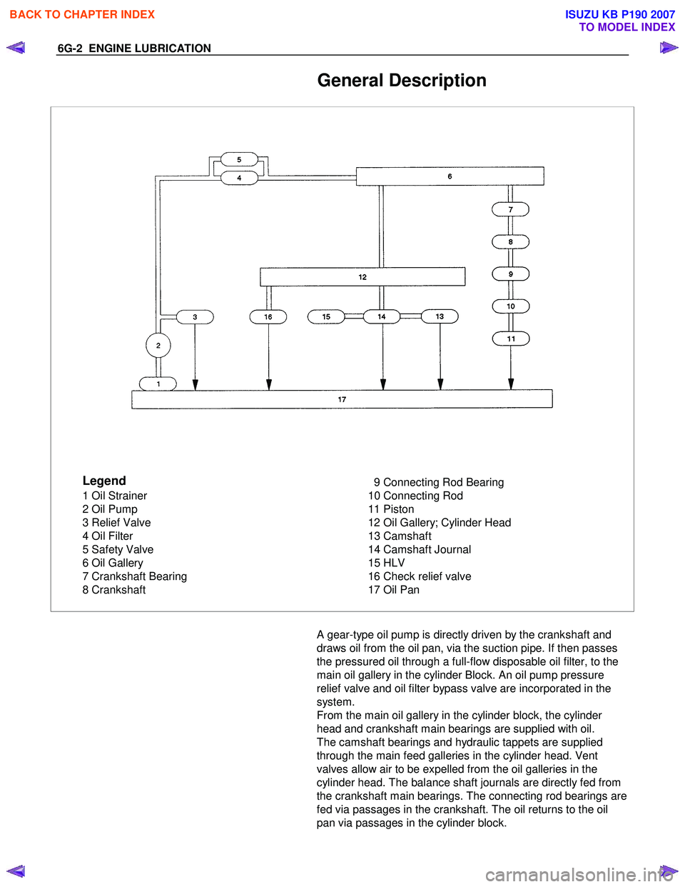
General Description
Legend
1 Oil Strainer
2 Oil Pump
3 Relief Valve
4 Oil Filter
5 Safety Valve
6 Oil Gallery
7 Crankshaft Bearing
8 Crankshaft 9 Connecting Rod Bearing
10 Connecting Rod
11 Piston
12 Oil Gallery; Cylinder Head
13 Camshaft
14 Camshaft Journal
15 HLV
16 Check relief valve
17 Oil Pan
A gear-type oil pump is directly driven by the crankshaft and
draws oil from the oil pan, via the suction pipe. If then passes
the pressured oil through a full-flow disposable oil filter, to the
main oil gallery in the cylinder Block. An oil pump pressure
relief valve and oil filter bypass valve are incorporated in the
system.
From the main oil gallery in the cylinder block, the cylinder
head and crankshaft main bearings are supplied with oil.
The camshaft bearings and hydraulic tappets are supplied
through the main feed galleries in the cylinder head. Vent
valves allow air to be expelled from the oil galleries in the
cylinder head. The balance shaft journals are directly fed from
the crankshaft main bearings. The connecting rod bearings are
fed via passages in the crankshaft. The oil returns to the oil
pan via passages in the cylinder block.
BACK TO CHAPTER INDEX
TO MODEL INDEX
ISUZU KB P190 2007
Page 2469 of 6020
ENGINE LUBRICATION 6G-5
Inspection and Repair
CAUTION: Make necessary correction or parts
replacement if wear, damage or any other abnormal
conditions are found through inspection.
Body and Gears
The pump assembly must be replaced if one or more of the
conditions below is discovered during inspection:
Indentation of gear pair - Use feeler strip and straight edge.
Dimension: 0.03 mm to 0.10 mm
(0.0012 to 0.0039 in)
Oil Strainer
Check the oil strainer for cracking and scoring. If cracking and
scoring are found, the oil strainer must be replaced.
Reassembly
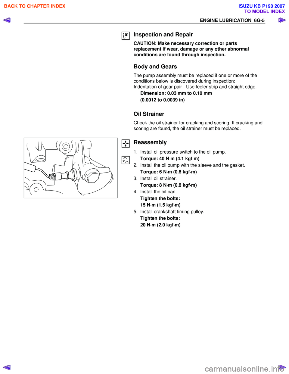
1. Install oil pressure switch to the oil pump.
Torque: 40 N ⋅
⋅⋅
⋅
m (4.1 kgf ⋅
⋅⋅
⋅
m)
2. Install the oil pump with the sleeve and the gasket.
Torque: 6 N ⋅
⋅⋅
⋅
m (0.6 kgf ⋅
⋅⋅
⋅
m)
3. Install oil strainer.
Torque: 8 N ⋅
⋅⋅
⋅
m (0.8 kgf ⋅
⋅⋅
⋅
m)
4. Install the oil pan.
Tighten the bolts:
15 N ⋅
⋅⋅
⋅
m (1.5 kgf ⋅
⋅⋅
⋅
m)
5. Install crankshaft timing pulley.
Tighten the bolts:
20 N ⋅
⋅⋅
⋅
m (2.0 kgf ⋅
⋅⋅
⋅
m)
BACK TO CHAPTER INDEX
TO MODEL INDEX
ISUZU KB P190 2007
Page 2475 of 6020
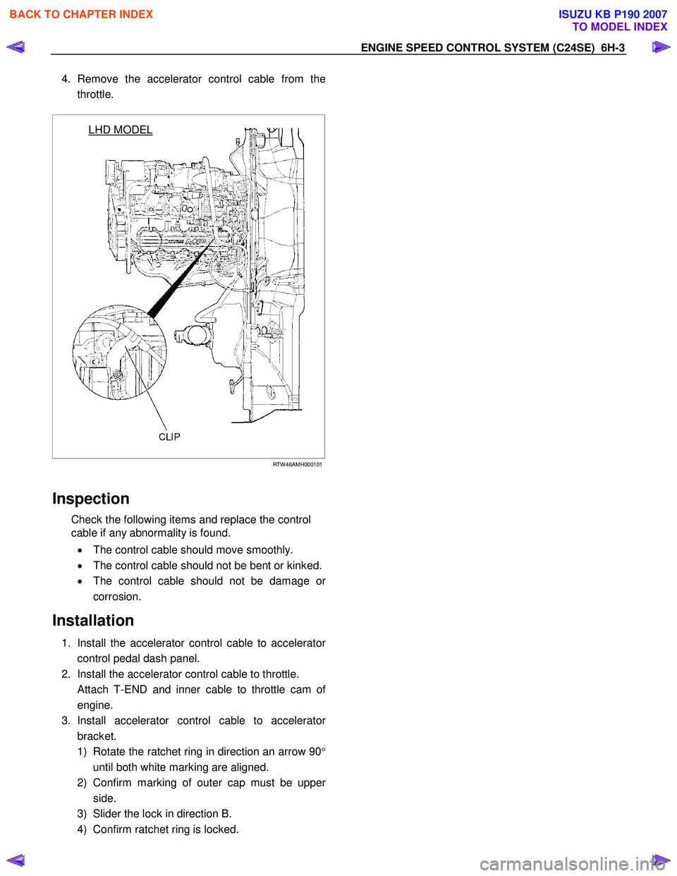
4. Remove the accelerator control cable from the
throttle.
LHD MODEL
RTW 46AMH000101
Inspection
Check the following items and replace the control
cable if any abnormality is found.
• The control cable should move smoothly.
• The control cable should not be bent or kinked.
• The control cable should not be damage o
r
corrosion.
Installation
1. Install the accelerator control cable to accelerator
control pedal dash panel.
2. Install the accelerator control cable to throttle.
Attach T-END and inner cable to throttle cam o
f
engine.
3. Install accelerator control cable to accelerato
r
bracket.
1) Rotate the ratchet ring in direction an arrow 90 °
until both white marking are aligned.
2) Confirm marking of outer cap must be uppe
r
side.
3) Slider the lock in direction B.
4) Confirm ratchet ring is locked.
EN
GIN E SPEED CONTR O L SY STEM (C 24SE) 6H-3
BACK TO CHAPTER INDEX
TO MODEL INDEX
ISUZU KB P190 2007
Page 2481 of 6020
Engine Mechanical – V6 Page 6A1–2
Visual / Physical Inspection ................................................................................................................................ 28
Intermittent ........................................................................................................................................................... 28
2.3 Engine Misfire without Internal Engine Noises .................................................................................. ............... 29
2.4 Engine Misfire with Abnormal Internal Lower Engine Noises...................................................................... .... 30
2.5 Engine Misfire with Abnormal Valve Train Noise .............................................................................................. 31
2.6 Engine Misfire with Coolant Consumption ........................................................................................................ 31
2.7 Engine Misfire with Excessive Oil Consumption .................................................................................. ............ 31
2.8 Engine Noise on Start-up, but only Lasting a Few Seconds ....................................................................... ..... 31
2.9 Upper Engine Noise, Regardless of Engine Speed........................................................................................... 33
2.10 Lower Engine Noise, Regardless of Engine Speed ................................................................................. ......... 34
2.11 Engine Noise Under Load ................................................................................................................................... 35
2.12 Engine Will Not Crank – Crankshaft Will Not Rotate ............................................................................. ........... 35
2.13 Coolant in Combustion Chamber ....................................................................................................................... 37
Definition .............................................................................................................................................................. 37
2.14 Coolant in Engine Oil.......................................................................................................... ................................. 37
Definition .............................................................................................................................................................. 37
2.15 Engine Compression Test ........................................................................................................ ........................... 38
Preliminary Steps................................................................................................................................................. 38
Engine Cylinder Compression Test ............................................................................................... .................... 38
Test Result Evaluation......................................................................................................................................... 38
2.16 Cylinder Leakage Test .......................................................................................................... ............................... 39
2.17 Engine Oil Consumption Diagnosis ............................................................................................... .................... 39
Definition .............................................................................................................................................................. 39
2.18 Engine Oil Leak Diagnosis ...................................................................................................... ............................ 40
Introduction .......................................................................................................................................................... 40
Locating and Identifying the Leak .............................................................................................. ........................ 40
Visual Inspection ................................................................................................................................................. 40
Powder Method .................................................................................................................. .................................. 40
Black Light and Dye Method ..................................................................................................... .......................... 40
Possible Causes for Engine Oil Leaks ........................................................................................... .................... 41
2.19 Engine Oil Pressure Diagnosis ........................................................................................................................... 42
2.20 Accessory Drive Belt Diagnosis ................................................................................................. ........................ 42
Tension Check ..................................................................................................................................................... 42
Inspect .................................................................................................................................................................. 42
Drive Belt Chirp .................................................................................................................................................... 43
Definition .......................................................................................................................................................... 43
Diagnostic Aids................................................................................................................................................. 43
Test Description ............................................................................................................... ................................ 43
Diagnostic Table............................................................................................................................................... 44
Drive Belt Squeal .............................................................................................................. ................................... 45
Definition .......................................................................................................................................................... 45
Diagnostic Aids................................................................................................................................................. 45
Test Description ............................................................................................................... ................................ 45
Diagnostic Table............................................................................................................................................... 46
Drive Belt Whine ............................................................................................................... ................................... 46
Definition .......................................................................................................................................................... 46
Diagnostic Aids................................................................................................................................................. 46
Test Description ............................................................................................................... ................................ 46
Diagnostic Table............................................................................................................................................... 47
Drive Belt Rumble .............................................................................................................. .................................. 47
Definition .......................................................................................................................................................... 47
Diagnostic Aids................................................................................................................................................. 48
Test Description ............................................................................................................... ................................ 48
Diagnostic Table............................................................................................................................................... 48
Drive Belt Vibration........................................................................................................... ................................... 49
Definition .......................................................................................................................................................... 49
Diagnostic Aids................................................................................................................................................. 49
Test Description ............................................................................................................... ................................ 49
Diagnostic Table............................................................................................................................................... 50
Drive Belt Falls Off ........................................................................................................... .................................... 50
BACK TO CHAPTER INDEX
TO MODEL INDEX
ISUZU KB P190 2007
Page 2482 of 6020
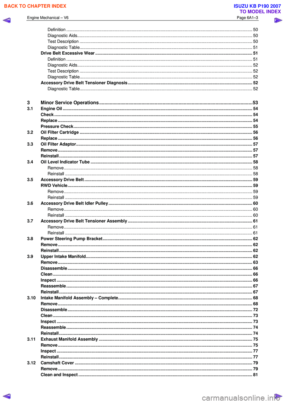
Engine Mechanical – V6 Page 6A1–3
Definition .......................................................................................................................................................... 50
Diagnostic Aids................................................................................................................................................. 50
Test Description ............................................................................................................... ................................ 50
Diagnostic Table............................................................................................................................................... 51
Drive Belt Excessive Wear ...................................................................................................... ............................ 51
Definition .......................................................................................................................................................... 51
Diagnostic Aids................................................................................................................................................. 52
Test Description ............................................................................................................... ................................ 52
Diagnostic Table............................................................................................................................................... 52
Accessory Drive Belt Tensioner Diagnosis ....................................................................................... ................ 52
Diagnostic Table............................................................................................................................................... 52
3 Minor Service Operations ....................................................................................................... .............53
3.1 Engine Oil ............................................................................................................................................................. 54
Check .................................................................................................................................................................... 54
Replace ........................................................................................................................ ......................................... 54
Pressure Check ................................................................................................................. ................................... 55
3.2 Oil Filter Cartridge ............................................................................................................................................... 56
Replace ................................................................................................................................................................. 56
3.3 Oil Filter Adaptor............................................................................................................. ..................................... 57
Remove ................................................................................................................................................................. 57
Reinstall ................................................................................................................................................................ 57
3.4 Oil Level Indicator Tube ....................................................................................................... ............................... 58
Remove ............................................................................................................................................................ 58
Reinstall ........................................................................................................................................................... 58
3.5 Accessory Drive Belt ........................................................................................................... ................................ 59
RWD Vehicle ......................................................................................................................................................... 59
Remove ............................................................................................................................................................ 59
Reinstall ........................................................................................................................................................... 59
3.6 Accessory Drive Belt Idler Pulley .............................................................................................. ......................... 60
Remove ............................................................................................................................................................ 60
Reinstall ........................................................................................................................................................... 60
3.7 Accessory Drive Belt Tensioner Assembly ........................................................................................ ............... 61
Remove ............................................................................................................................................................ 61
Reinstall ........................................................................................................................................................... 61
3.8 Power Steering Pump Bracket .................................................................................................... ........................ 62
Remove ................................................................................................................................................................. 62
Reinstall ................................................................................................................................................................ 62
3.9 Upper Intake Manifold.......................................................................................................... ................................ 62
Remove ................................................................................................................................................................. 63
Disassemble ......................................................................................................................................................... 66
Clean ..................................................................................................................................................................... 66
Inspect .................................................................................................................................................................. 66
Reassemble .......................................................................................................................................................... 67
Reinstall ...................................................................................................................... .......................................... 67
3.10 Intake Manifold Assembly – Complete............................................................................................ ................... 68
Remove ................................................................................................................................................................. 68
Disassemble ......................................................................................................................................................... 72
Clean ..................................................................................................................................................................... 73
Inspect .................................................................................................................................................................. 73
Reassemble .......................................................................................................................................................... 74
Reinstall ...................................................................................................................... .......................................... 74
3.11 Exhaust Manifold Assembly ...................................................................................................... ......................... 75
Remove ................................................................................................................................................................. 75
Inspect .................................................................................................................................................................. 77
Reinstall ................................................................................................................................................................ 77
3.12 Camshaft Cover ................................................................................................................. .................................. 79
Remove ................................................................................................................................................................. 79
Clean and Inspect .............................................................................................................. .................................. 81
BACK TO CHAPTER INDEX
TO MODEL INDEX
ISUZU KB P190 2007
Page 2494 of 6020

Engine Mechanical – V6 Page 6A1–15
Cylinder Head Assembly
Figure 6A1 – 7
Legend
1 Cylinder Head, Left-hand
2 Cylinder Head, Right-hand
3 Cylinder Head Gasket, Left-hand
4 Cylinder Head Gasket, Right-hand
5 Cylinder Head Bolt
6 Cylinder Head Front Bolt
7 Cylinder Head Coolant Hole Threaded Plug
8 Spark Plug Sleeve
9 Cylinder Head Oil Gallery Expansion Plug
10 Exhaust Valve
11 Intake Valve
12 Valve Rocker Arm Assembly
13 Hydraulic Valve Lash Adjuster Assembly
14 Valve Stem Oil Seal 15 Valve Spring
16 Valve Spring Cap
17 Valve Stem Key
18 Cylinder Head Camshaft Front Thrust Bearing Cap
19 Camshaft Oil Seal Ring
20 Exhaust Camshaft
21 Intake Camshaft, Left-hand (bank 2)
22 Intake Camshaft, Right-hand (bank 1)
23 Exhaust Camshaft, Right-hand (bank 1)
24 Cylinder Head Camshaft Cap – Intermediate
25 Cylinder Head Camshaft Cap Bolt
26 Cylinder Head Oil Galley Check Valve
27 Engine Coolant Temperature Sensor
BACK TO CHAPTER INDEX
TO MODEL INDEX
ISUZU KB P190 2007
Page 2507 of 6020
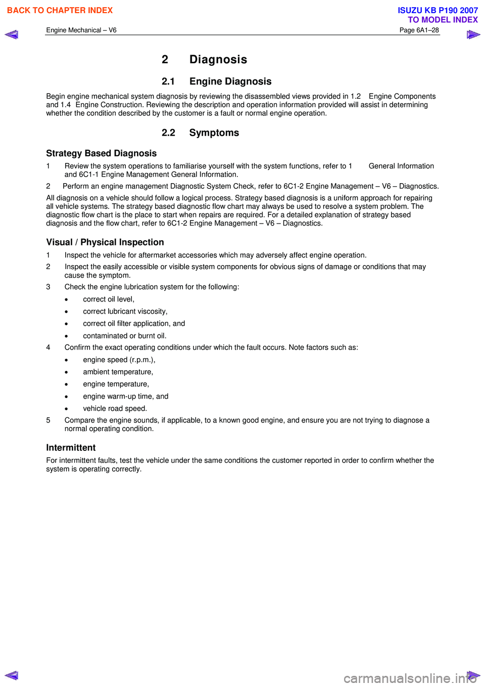
Engine Mechanical – V6 Page 6A1–28
2 Diagnosis
2.1 Engine Diagnosis
Begin engine mechanical system diagnosis by reviewing the disassembled views provided in 1.2 Engine Components
and 1.4 Engine Construction. Reviewing the description and operation information provided will assist in determining
whether the condition described by the customer is a fault or normal engine operation.
2.2 Symptoms
Strategy Based Diagnosis
1 Review the system operations to familiarise yourself with the system functions, refer to 1 General Information and 6C1-1 Engine Management General Information.
2 Perform an engine management Diagnostic System Check, refer to 6C1-2 Engine Management – V6 – Diagnostics.
All diagnosis on a vehicle should follow a logical process. Strategy based diagnosis is a uniform approach for repairing
all vehicle systems. The strategy based diagnostic flow chart may always be used to resolve a system problem. The
diagnostic flow chart is the place to start when repairs are required. For a detailed explanation of strategy based
diagnosis and the flow chart, refer to 6C1-2 Engine Management – V6 – Diagnostics.
Visual / Physical Inspection
1 Inspect the vehicle for aftermarket accessories which may adversely affect engine operation.
2 Inspect the easily accessible or visible system components for obvious signs of damage or conditions that may cause the symptom.
3 Check the engine lubrication system for the following:
• correct oil level,
• correct lubricant viscosity,
• correct oil filter application, and
• contaminated or burnt oil.
4 Confirm the exact operating conditions under which the fault occurs. Note factors such as:
• engine speed (r.p.m.),
• ambient temperature,
• engine temperature,
• engine warm-up time, and
• vehicle road speed.
5 Compare the engine sounds, if applicable, to a known good engine, and ensure you are not trying to diagnose a normal operating condition.
Intermittent
For intermittent faults, test the vehicle under the same conditions the customer reported in order to confirm whether the
system is operating correctly.
BACK TO CHAPTER INDEX
TO MODEL INDEX
ISUZU KB P190 2007
Page 2508 of 6020

Engine Mechanical – V6 Page 6A1–29
2.3 Engine Misfire without Internal Engine
Noises
Cause Correction
Abnormalities, severe cracking, bumps or missing areas in
the accessory drive belt.
Abnormalities in the accessory drive system and/or
components may cause engine speed variations that result
in a misfire diagnostic trouble code (DTC). A misfire code
may be present without an actual misfire condition. Replace the accessory drive belt, refer to 3.5
Accessory
Drive Belt.
Refer to 6C1-2 Engine Management – V6 – Diagnostics to
check for DTCs.
W orn, damaged or misaligned accessory drive components
and excessive pulley run-out may lead to a misfire DTC.
A misfire code may be present without an actual misfire
condition. Inspect the components and repair or replace as required.
Refer to 6C1-2 Engine Management – V6 – Diagnostics to
check for DTCs.
Loose or incorrectly fitted flexplate or crankshaft balancer
assembly.
A misfire DTC may be present without an actual misfire
condition. Repair or replace the flexplate or crankshaft balancer as
required, refer to 3.13 Crankshaft Balancer Assembly
or 4.3 Flexplate Assembly.
Refer to 6C1-2 Engine Management – V6 – Diagnostics to
check for DTCs
Restricted exhaust system.
A severe restriction in the exhaust flow can cause
significant loss of engine performance and may set a DTC.
Possible causes of restrictions in the exhaust system
include collapsed/dented pipes and blocked mufflers and/or
catalytic converters. Repair or replace exhaust system components as required,
refer to 8B Exhaust System.
Refer to 6C1-2 Engine Management – V6 – Diagnostics to
check for DTCs
Incorrectly installed or damaged vacuum hoses. Repair or replace vacuum hoses as required.
Incorrect sealing between the intake manifold and cylinder
heads, upper intake manifold and lower intake manifold,
throttle body and intake manifold. Repair or replace the intake manifold, throttle body gaskets,
cylinder heads, throttle body as required.
Incorrectly installed or damaged barometric
pressure(BARO) sensor and/or seal. The seal should not
be torn or damaged. Repair or replace the BARO sensor and/or seal as
required, refer to 6C1-3 Engine Management – V6 –
Service Operations.
Incorrectly installed or damaged EVAP purge solenoid
and/or O-ring seal. Repair or replace the EVAP purge solenoid and/or seal as
required, refer to 6C1-3 Engine Management – V6 –
Service Operations
W orn or loose stationary hydraulic lash adjusters (SHLA)
and/or rocker arms.
The SHLAs, rocker arms and roller bearings should be
intact and in the correct position. Replace the SHLAs and/or rocker arms as required, refer to
3.21 Stationary Hydraulic Lash Adjuster or 3.20
Rocker Arm.
Stuck valves.
Carbon build up on the valve stems can result in the valves
not closing correctly. Repair or replace as required, refer to 3.22 Cylinder Head
Assembly.
Excessively worn or misaligned timing chain/s. Replace the timing chain/s and components as required,
refer to 3.16 Timing Chains, Tensioners, Shoes and
Guides.
W orn camshaft lobes. Replace the camshaft/s and SHLAs as required, refer to
3.19 Camshaft or 3.21 Stationary Hydraulic Lash
Adjuster.
Excessive oil pressure.
A lubrication system with excessive oil pressure may lead
to excessive lash adjuster pump-up and loss of
compression. 1 Perform an oil pressure test, refer to 3.1
Engine Oil.
2 Repair or replace the engine oil pump as required, refer to 3.17 Oil Pump Assembly.
BACK TO CHAPTER INDEX
TO MODEL INDEX
ISUZU KB P190 2007
Page 2509 of 6020
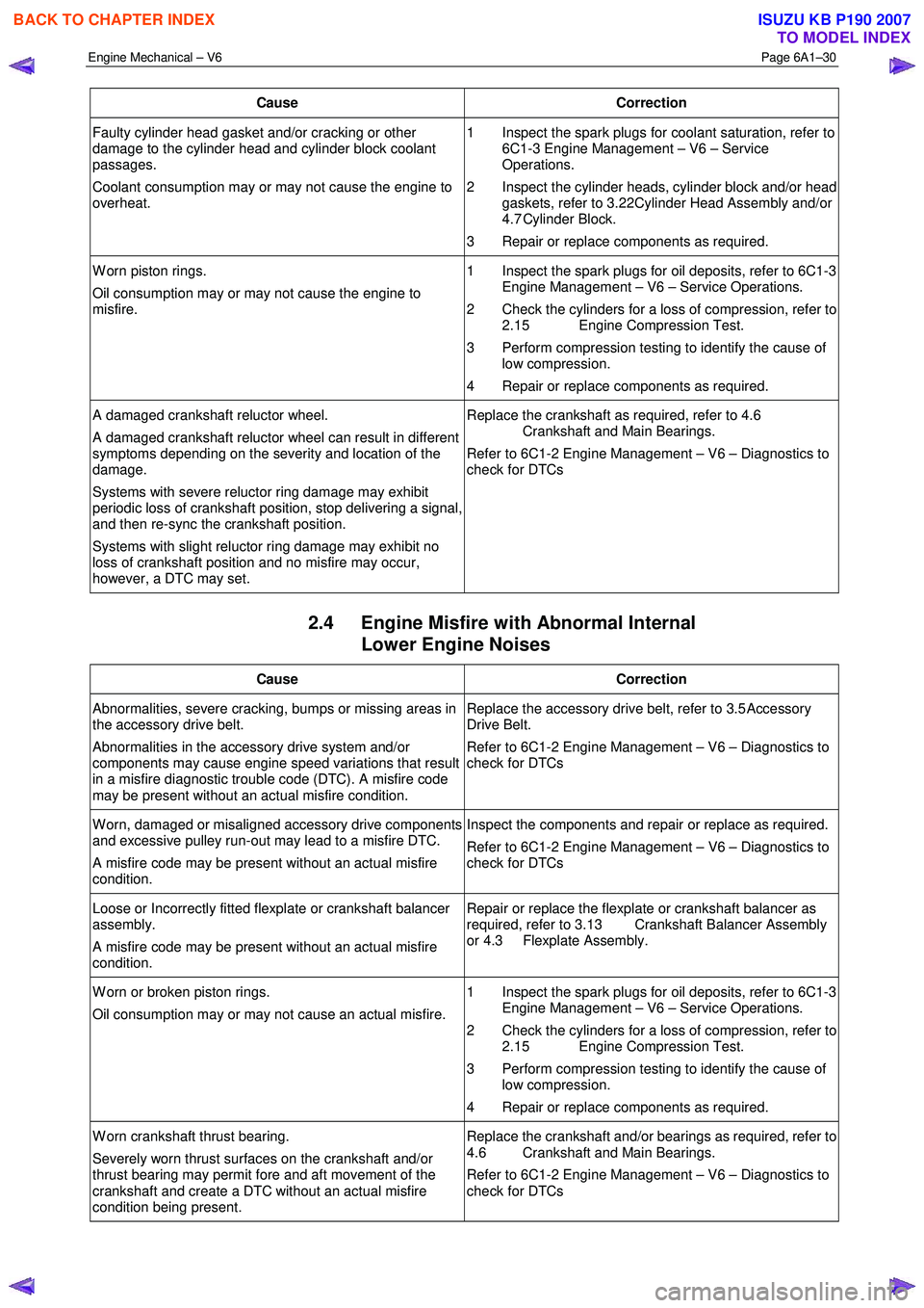
Engine Mechanical – V6 Page 6A1–30
Cause Correction
Faulty cylinder head gasket and/or cracking or other
damage to the cylinder head and cylinder block coolant
passages.
Coolant consumption may or may not cause the engine to
overheat. 1 Inspect the spark plugs for coolant saturation, refer to
6C1-3 Engine Management – V6 – Service
Operations.
2 Inspect the cylinder heads, cylinder block and/or head gaskets, refer to 3.22 Cylinder Head Assembly and/or
4.7 Cylinder Block.
3 Repair or replace components as required.
W orn piston rings.
Oil consumption may or may not cause the engine to
misfire. 1 Inspect the spark plugs for oil deposits, refer to 6C1-3
Engine Management – V6 – Service Operations.
2 Check the cylinders for a loss of compression, refer to 2.15 Engine Compression Test.
3 Perform compression testing to identify the cause of low compression.
4 Repair or replace components as required.
A damaged crankshaft reluctor wheel.
A damaged crankshaft reluctor wheel can result in different
symptoms depending on the severity and location of the
damage.
Systems with severe reluctor ring damage may exhibit
periodic loss of crankshaft position, stop delivering a signal,
and then re-sync the crankshaft position.
Systems with slight reluctor ring damage may exhibit no
loss of crankshaft position and no misfire may occur,
however, a DTC may set. Replace the crankshaft as required, refer to 4.6
Crankshaft and Main Bearings.
Refer to 6C1-2 Engine Management – V6 – Diagnostics to
check for DTCs
2.4 Engine Misfire with Abnormal Internal Lower Engine Noises
Cause Correction
Abnormalities, severe cracking, bumps or missing areas in
the accessory drive belt.
Abnormalities in the accessory drive system and/or
components may cause engine speed variations that result
in a misfire diagnostic trouble code (DTC). A misfire code
may be present without an actual misfire condition. Replace the accessory drive belt, refer to 3.5
Accessory
Drive Belt.
Refer to 6C1-2 Engine Management – V6 – Diagnostics to
check for DTCs
W orn, damaged or misaligned accessory drive components
and excessive pulley run-out may lead to a misfire DTC.
A misfire code may be present without an actual misfire
condition. Inspect the components and repair or replace as required.
Refer to 6C1-2 Engine Management – V6 – Diagnostics to
check for DTCs
Loose or Incorrectly fitted flexplate or crankshaft balancer
assembly.
A misfire code may be present without an actual misfire
condition. Repair or replace the flexplate or crankshaft balancer as
required, refer to 3.13 Crankshaft Balancer Assembly
or 4.3 Flexplate Assembly.
W orn or broken piston rings.
Oil consumption may or may not cause an actual misfire. 1 Inspect the spark plugs for oil deposits, refer to 6C1-3
Engine Management – V6 – Service Operations.
2 Check the cylinders for a loss of compression, refer to 2.15 Engine Compression Test.
3 Perform compression testing to identify the cause of low compression.
4 Repair or replace components as required.
W orn crankshaft thrust bearing.
Severely worn thrust surfaces on the crankshaft and/or
thrust bearing may permit fore and aft movement of the
crankshaft and create a DTC without an actual misfire
condition being present. Replace the crankshaft and/or bearings as required, refer to
4.6 Crankshaft and Main Bearings.
Refer to 6C1-2 Engine Management – V6 – Diagnostics to
check for DTCs
BACK TO CHAPTER INDEX
TO MODEL INDEX
ISUZU KB P190 2007
Page 2510 of 6020

Engine Mechanical – V6 Page 6A1–31
2.5 Engine Misfire with Abnormal Valve
Train Noise
Cause Correction
W orn or loose stationary hydraulic lash adjusters (SHLA)
and/or valve rocker arms.
The SHLAs, rocker arm and roller bearings should be intact
and in the correct position. Replace the SHLAs and/or rocker arms as required, refer to
3.21 Stationary Hydraulic Lash Adjuster or 3.20
Rocker Arm.
Stuck valves.
Carbon build up on the valve stems can result in the valves
not closing correctly. Repair or replace as required, refer to 3.22 Cylinder Head
Assembly.
Excessively worn or misaligned timing chain/s. Replace the timing chain/s and components as required,
refer to 3.16 Timing Chains, Tensioners, Shoes and
Guides.
W orn camshaft lobes. Replace the camshaft/s and SHLAs as required, refer to
3.19 Camshaft or 3.21 Stationary Hydraulic Lash
Adjuster.
Sticking camshaft lash adjusters. Replace the lash adjusters as required, refer to 3.21
Stationary Hydraulic Lash Adjuster.
2.6 Engine Misfire with Coolant
Consumption
Cause Correction
Faulty cylinder head gasket and/or cracking or other
damage to the cylinder heads and cylinder block coolant
passages.
Coolant consumption may or may not cause the engine to
overheat. 1 Inspect the spark plugs for coolant saturation, refer to
6C1-3 Engine Management – V6 – Service
Operations.
2 Inspect the cylinder heads, cylinder block and/or head gaskets, refer to 3.22 Cylinder Head Assembly and/or
4.7 Cylinder Block.
3 Repair or replace components as required.
2.7 Engine Misfire with Excessive Oil Consumption
Cause Correction
W orn valves, valve guides and/or valve stem oil seals. 1 Inspect the spark plugs for coolant saturation, refer to 6C1-3 Engine Management – V6 – Service
Operations.
2 Repair or replace components as required, refer to 3.22 Cylinder Head Assembly.
W orn or broken piston rings.
Oil consumption may or may not cause an actual misfire. 1 Inspect the spark plugs for oil deposits, refer to 6C1-3
Engine Management – V6 – Service Operations.
2 Check the cylinders for a loss of compression, refer to 2.15 Engine Compression Test.
3 Perform compression testing to identify the cause of low compression.
4 Repair or replace components as required.
2.8 Engine Noise on Start-up, but only Lasting a Few Seconds
NOTE
A cold piston knock, which disappears in
approximately 1.5 minutes from start up, should
be considered acceptable. A cold engine knock
usually disappears when the specific cylinder’s
BACK TO CHAPTER INDEX
TO MODEL INDEX
ISUZU KB P190 2007