body ISUZU KB P190 2007 Workshop Manual PDF
[x] Cancel search | Manufacturer: ISUZU, Model Year: 2007, Model line: KB P190, Model: ISUZU KB P190 2007Pages: 6020, PDF Size: 70.23 MB
Page 875 of 6020
6A – 70 ENGINE MECHANICAL
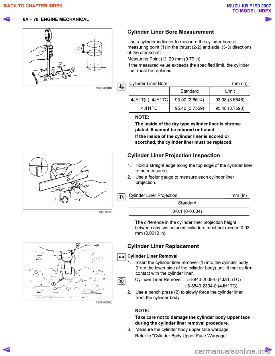
Cylinder Liner Bore Measurement
Use a cylinder indicator to measure the cylinder bore at
measuring point (1) in the thrust (2-2) and axial (3-3) directions
of the crankshaft.
Measuring Point (1): 20 mm (0.79 in)
If the measured value exceeds the specified limit, the cylinder
liner must be replaced.
Cylinder Liner Bore mm (in)
Standard Limit
4JA1T(L), 4JA1TC 93.00 (3.6614) 93.08 (3.6646)
4JH1TC 95.40 (3.7559) 95.48 (3.7590)
NOTE:
The inside of the dry type cylinder liner is chrome
plated. It cannot be rebored or honed.
If the inside of the cylinder liner is scored or
scorched, the cylinder liner must be replaced.
Cylinder Liner Projection Inspection
1. Hold a straight edge along the top edge of the cylinder liner
to be measured.
2. Use a feeler gauge to measure each cylinder liner projection.
Cylinder Liner Projection mm (in)
Standard
0-0.1 (0-0.004)
The difference in the cylinder liner projection height
between any two adjacent cylinders must not exceed 0.03
mm (0.0012 in).
Cylinder Liner Replacement
Cylinder Liner Removal
1. Insert the cylinder liner remover (1) into the cylinder body (from the lower side of the cylinder body) until it makes firm
contact with the cylinder liner.
Cylinder Liner Remover : 5-8840-2039-0 (4JA1L/TC)
: 5-8840-2304-0 (4JH1TC)
2. Use a bench press (2) to slowly force the cylinder liner from the cylinder body.
NOTE:
Take care not to damage the cylinder body upper face
during the cylinder liner removal procedure.
3. Measure the cylinder body upper face warpage. Refer to "Cylinder Body Upper Face Warpage".
012RY00010
012LX016
012RY00012
BACK TO CHAPTER INDEX
TO MODEL INDEX
ISUZU KB P190 2007
Page 876 of 6020
ENGINE MECHANICAL 6A – 71
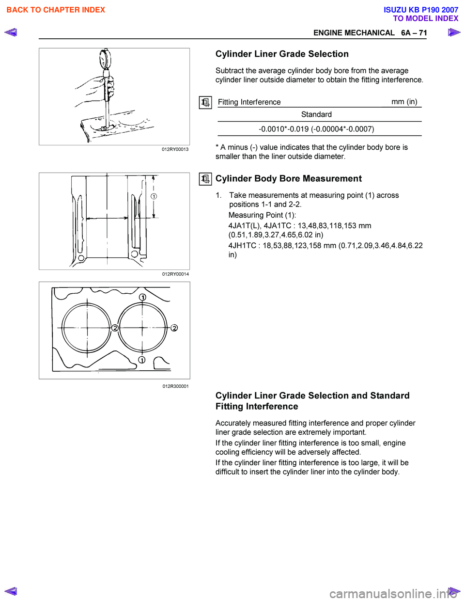
Cylinder Liner Grade Selection
Subtract the average cylinder body bore from the average
cylinder liner outside diameter to obtain the fitting interference.
Fitting Interference mm
(in)
Standard
-0.0010*-0.019 (-0.00004*-0.0007)
* A minus (-) value indicates that the cylinder body bore is
smaller than the liner outside diameter.
Cylinder Body Bore Measurement
1. Take measurements at measuring point (1) across positions 1-1 and 2-2.
Measuring Point (1):
4JA1T(L), 4JA1TC : 13,48,83,118,153 mm
(0.51,1.89,3.27,4.65,6.02 in)
4JH1TC : 18,53,88,123,158 mm (0.71,2.09,3.46,4.84,6.22
in)
Cylinder Liner Grade Selection and Standard
Fitting Interference
Accurately measured fitting interference and proper cylinder
liner grade selection are extremely important.
If the cylinder liner fitting interference is too small, engine
cooling efficiency will be adversely affected.
If the cylinder liner fitting interference is too large, it will be
difficult to insert the cylinder liner into the cylinder body.
012RY00013
012RY00014 012R300001
BACK TO CHAPTER INDEX
TO MODEL INDEX
ISUZU KB P190 2007
Page 877 of 6020
6A – 72 ENGINE MECHANICAL
012RY00022
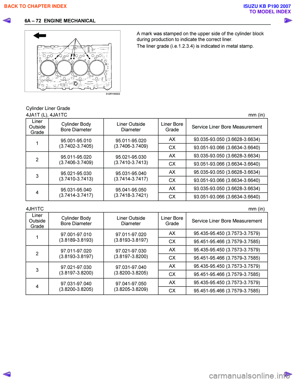
A mark was stamped on the upper side of the cylinder block
during production to indicate the correct liner.
The liner grade (i.e.1.2.3.4) is indicated in metal stamp.
Cylinder Liner Grade
4JA1T (L), 4JA1TC mm (in)
Liner
Outside Grade Cylinder Body
Bore Diameter Liner Outside
Diameter Liner Bore
Grade Service Liner Bore Measurement
AX 93.035-93.050 (3.6628-3.6634) 1 95.001-95.010
(3.7402-3.7405) 95.011-95.020
(3.7406-3.7409) CX 93.051-93.066 (3.6634-3.6640)
AX 93.035-93.050 (3.6628-3.6634) 2 95.011-95.020
(3.7406-3.7409) 95.021-95.030
(3.7410-3.7413) CX 93.051-93.066 (3.6634-3.6640)
AX 95.035-93.050 (3.6628-3.6634) 3 95.021-95.030
(3.7410-3.7413) 95.031-95.040
(3.7414-3.7417) CX 93.051-93.066 (3.6634-3.6640)
AX 93.035-93.050 (3.6628-3.6634) 4 95.031-95.040
(3.7414-3.7417) 95.041-95.050
(3.7418-3.7421) CX 93.051-93.066 (3.6634-3.6640)
4JH1TC mm (in)
Liner
Outside Grade Cylinder Body
Bore Diameter Liner Outside
Diameter Liner Bore
Grade Service Liner Bore Measurement
AX 95.435-95.450 (3.7573-3.7579) 1 97.001-97.010
(3.8189-3.8193) 97.011-97.020
(3.8193-3.8197) CX 95.451-95.466 (3.7579-3.7585)
AX 95.435-95.450 (3.7573-3.7579) 2 97.011-97.020
(3.8193-3.8197) 97.021-97.030
(3.8197-3.8200) CX 95.451-95.466 (3.7579-3.7585)
AX 95.435-95.450 (3.7573-3.7579) 3 97.021-97.030
(3.8197-3.8200) 97.031-97.040
(3.8200-3.8205) CX 95.451-95.466 (3.7579-3.7585)
AX 95.435-95.450 (3.7573-3.7579) 4 97.031-97.040
(3.8200-3.8205) 97.041-97.050
(3.8205-3.8209) CX 95.451-95.466 (3.7579-3.7585)
BACK TO CHAPTER INDEX
TO MODEL INDEX
ISUZU KB P190 2007
Page 878 of 6020
ENGINE MECHANICAL 6A – 73
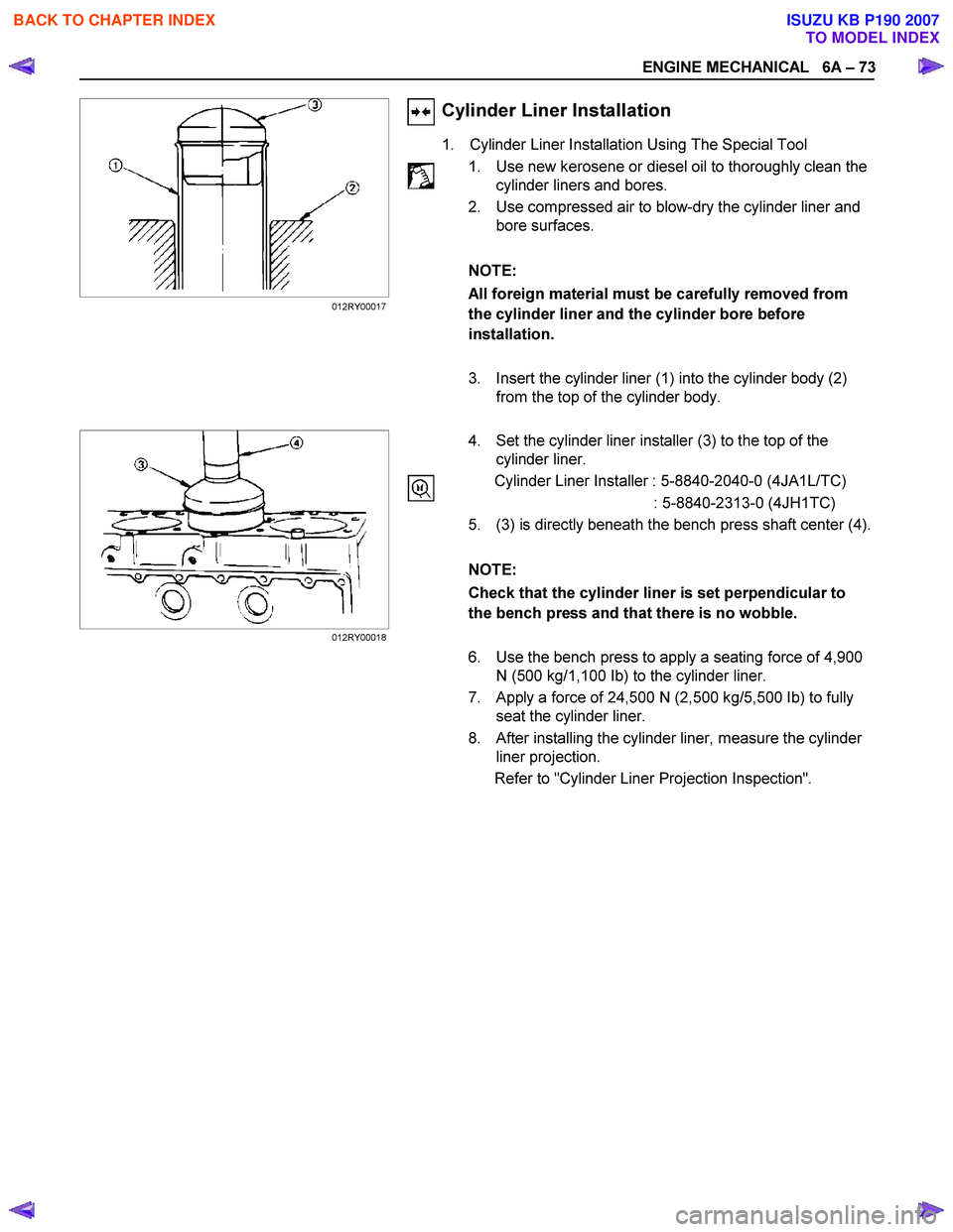
Cylinder Liner Installation
1. Cylinder Liner Installation Using The Special Tool
1. Use new kerosene or diesel oil to thoroughly clean the cylinder liners and bores.
2. Use compressed air to blow-dry the cylinder liner and bore surfaces.
NOTE:
All foreign material must be carefully removed from
the cylinder liner and the cylinder bore before
installation.
3. Insert the cylinder liner (1) into the cylinder body (2) from the top of the cylinder body.
4. Set the cylinder liner installer (3) to the top of the
cylinder liner.
Cylinder Liner Installer : 5-8840-2040-0 (4JA1L/TC)
: 5-8840-2313-0 (4JH1TC)
5. (3) is directly beneath the bench press shaft center (4).
NOTE:
Check that the cylinder liner is set perpendicular to
the bench press and that there is no wobble.
6. Use the bench press to apply a seating force of 4,900 N (500 kg/1,100 Ib) to the cylinder liner.
7. Apply a force of 24,500 N (2,500 kg/5,500 Ib) to fully seat the cylinder liner.
8. After installing the cylinder liner, measure the cylinder liner projection.
Refer to "Cylinder Liner Projection Inspection".
012RY00017
012RY00018
BACK TO CHAPTER INDEX
TO MODEL INDEX
ISUZU KB P190 2007
Page 881 of 6020
6A – 76 ENGINE MECHANICAL
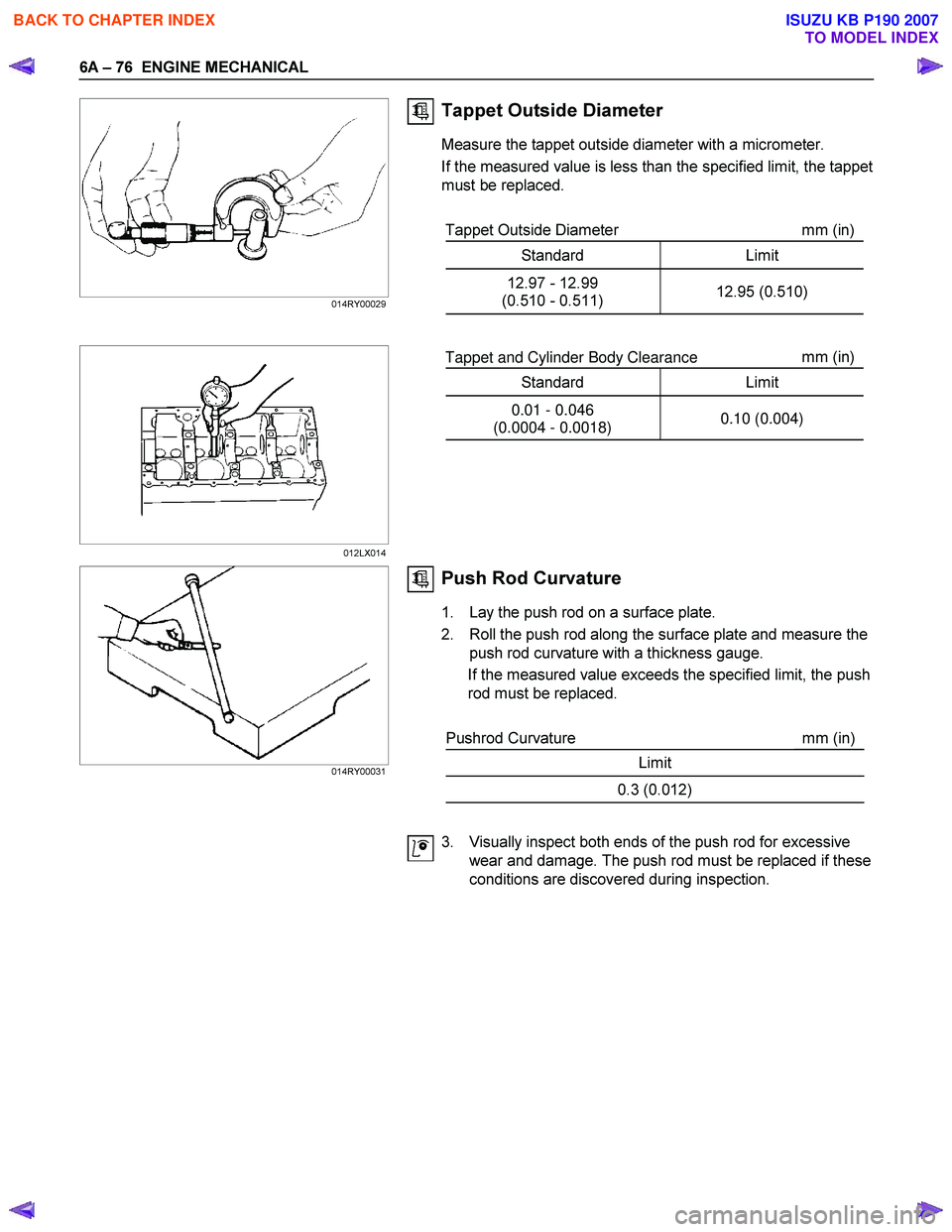
Tappet Outside Diameter
Measure the tappet outside diameter with a micrometer.
If the measured value is less than the specified limit, the tappet
must be replaced.
Tappet Outside Diameter mm (in)
Standard Limit
12.97 - 12.99
(0.510 - 0.511) 12.95 (0.510)
Tappet and Cylinder Body Clearance mm
(in)
Standard Limit
0.01 - 0.046
(0.0004 - 0.0018) 0.10 (0.004)
Push Rod Curvature
1. Lay the push rod on a surface plate.
2. Roll the push rod along the surface plate and measure the push rod curvature with a thickness gauge.
If the measured value exceeds the specified limit, the push
rod must be replaced.
Pushrod Curvature mm (in)
Limit
0.3 (0.012)
3. Visually inspect both ends of the push rod for excessive wear and damage. The push rod must be replaced if these
conditions are discovered during inspection.
014RY00029
012LX014
014RY00031
BACK TO CHAPTER INDEX
TO MODEL INDEX
ISUZU KB P190 2007
Page 883 of 6020
6A – 78 ENGINE MECHANICAL
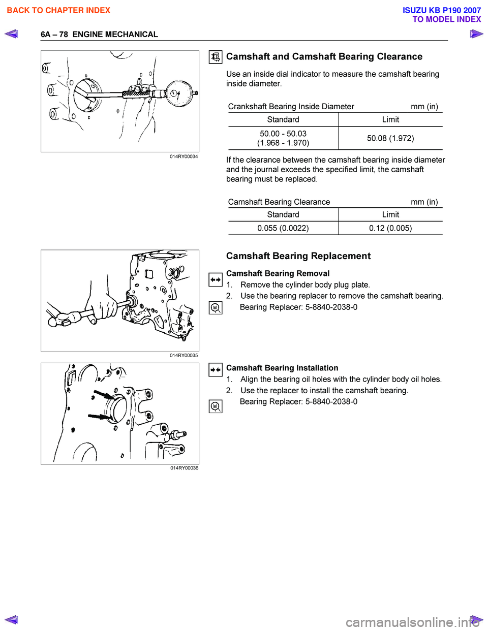
Camshaft and Camshaft Bearing Clearance
Use an inside dial indicator to measure the camshaft bearing
inside diameter.
Crankshaft Bearing Inside Diameter mm (in)
Standard Limit
50.00 - 50.03
(1.968 - 1.970) 50.08 (1.972)
If the clearance between the camshaft bearing inside diameter
and the journal exceeds the specified limit, the camshaft
bearing must be replaced.
Camshaft Bearing Clearance mm (in)
Standard Limit
0.055 (0.0022) 0.12 (0.005)
Camshaft Bearing Replacement
Camshaft Bearing Removal
1. Remove the cylinder body plug plate.
2. Use the bearing replacer to remove the camshaft bearing. Bearing Replacer: 5-8840-2038-0
Camshaft Bearing Installation
1. Align the bearing oil holes with the cylinder body oil holes.
2. Use the replacer to install the camshaft bearing. Bearing Replacer: 5-8840-2038-0
014RY00034
014RY00035 014RY00036
BACK TO CHAPTER INDEX
TO MODEL INDEX
ISUZU KB P190 2007
Page 886 of 6020
ENGINE MECHANICAL 6A – 81
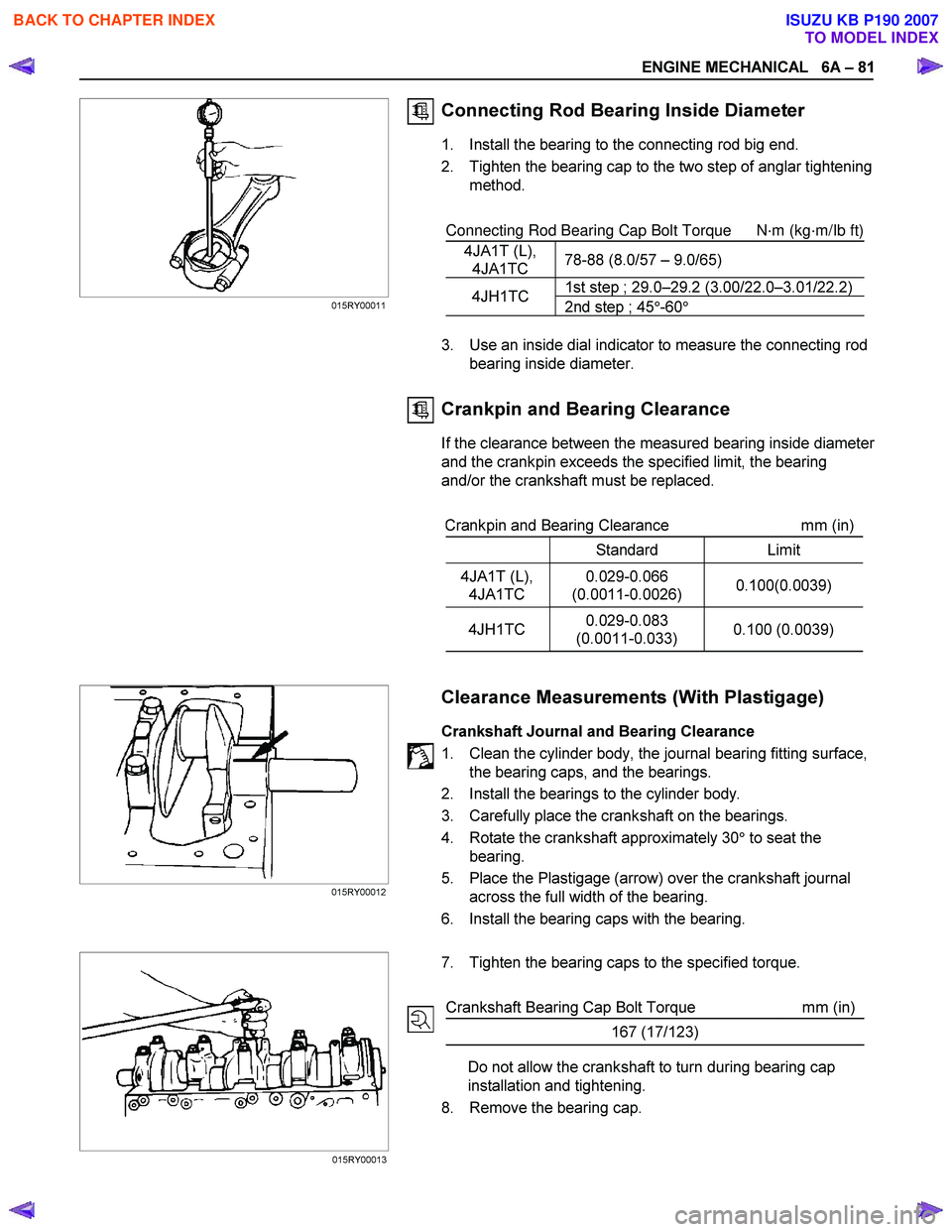
Connecting Rod Bearing Inside Diameter
1. Install the bearing to the connecting rod big end.
2. Tighten the bearing cap to the two step of anglar tightening method.
Connecting Rod Bearing Cap Bolt Torque
N·m (kg·m/Ib ft)
4JA1T (L), 4JA1TC 78-88 (8.0/57 – 9.0/65)
1st step ; 29.0–29.2 (3.00/22.0–3.01/22.2)4JH1TC
2nd step ; 45°-60 °
3. Use an inside dial indicator to measure the connecting rod
bearing inside diameter.
Crankpin and Bearing Clearance
If the clearance between the measured bearing inside diameter
and the crankpin exceeds the specified limit, the bearing
and/or the crankshaft must be replaced.
Crankpin and Bearing Clearance mm (in)
Standard Limit
4JA1T (L),
4JA1TC 0.029-0.066
(0.0011-0.0026) 0.100(0.0039)
4JH1TC
0.029-0.083
(0.0011-0.033) 0.100 (0.0039)
Clearance Measurements (With Plastigage)
Crankshaft Journal and Bearing Clearance
1. Clean the cylinder body, the journal bearing fitting surface, the bearing caps, and the bearings.
2. Install the bearings to the cylinder body.
3. Carefully place the crankshaft on the bearings.
4. Rotate the crankshaft approximately 30 ° to seat the
bearing.
5. Place the Plastigage (arrow) over the crankshaft journal across the full width of the bearing.
6. Install the bearing caps with the bearing.
7. Tighten the bearing caps to the specified torque.
Crankshaft Bearing Cap Bolt Torque mm (in)
167 (17/123)
Do not allow the crankshaft to turn during bearing cap
installation and tightening.
8. Remove the bearing cap.
015RY00012
015RY00013
015RY00011
BACK TO CHAPTER INDEX
TO MODEL INDEX
ISUZU KB P190 2007
Page 888 of 6020
ENGINE MECHANICAL 6A – 83
6. Remove the bearing cap.
7. Compare the width of the Plastigage attached to either the crankshaft or the bearing against the scale printed on the
Plastigage container.
If the measured value exceeds the specified limit, perform
the following additional steps.
1. Use a micrometer to measure the crankpin outside diameter.
2. Use an inside dial indicator to measure the bearing inside diameter.
If the crank pin and bearing clearance exceeds the
specified limit, the crankshaft and/or the bearing must
be replaced.
Crankpin and Bearing Clearance mm (in)
Standard Limit
4JA1T (L),
4JA1TC 0.029-0.066
(0.0011-0.0026) 0.100 (0.0039)
4JH1TC
0.029-0.083
(0.0011-0.0033) 0.100 (0.0039)
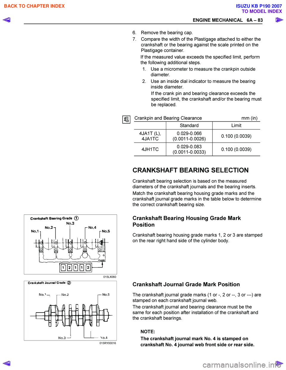
CRANKSHAFT BEARING SELECTION
Crankshaft bearing selection is based on the measured
diameters of the crankshaft journals and the bearing inserts.
Match the crankshaft bearing housing grade marks and the
crankshaft journal grade marks in the table below to determine
the correct crankshaft bearing size.
Crankshaft Bearing Housing Grade Mark
Position
Crankshaft bearing housing grade marks 1, 2 or 3 are stamped
on the rear right hand side of the cylinder body.
Crankshaft Journal Grade Mark Position
The crankshaft journal grade marks (1 or -, 2 or --, 3 or ---) are
stamped on each crankshaft journal web.
The crankshaft journal and bearing clearance must be the
same for each position after installation of the crankshaft and
the crankshaft bearings.
NOTE:
The crankshaft journal mark No. 4 is stamped on
crankshaft No. 4 journal web front side or rear side.
015LX060
015RY00016
BACK TO CHAPTER INDEX
TO MODEL INDEX
ISUZU KB P190 2007
Page 891 of 6020
6A – 86 ENGINE MECHANICAL
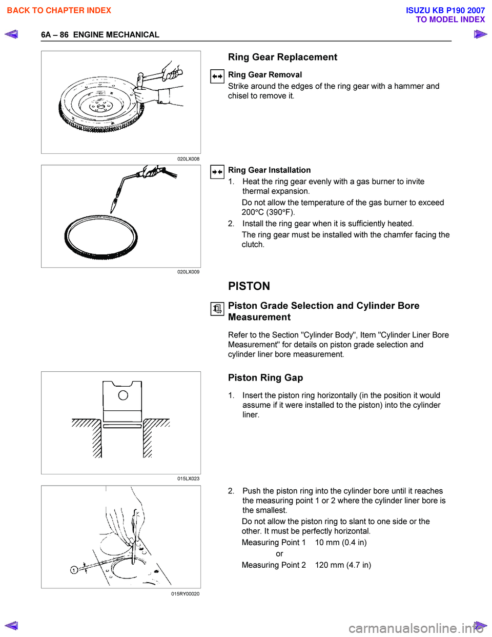
Ring Gear Replacement
Ring Gear Removal
Strike around the edges of the ring gear with a hammer and
chisel to remove it.
Ring Gear Installation
1. Heat the ring gear evenly with a gas burner to invite thermal expansion.
Do not allow the temperature of the gas burner to exceed
200 °C (390 °F).
2. Install the ring gear when it is sufficiently heated. The ring gear must be installed with the chamfer facing the
clutch.
PISTON
Piston Grade Selection and Cylinder Bore
Measurement
Refer to the Section "Cylinder Body", Item "Cylinder Liner Bore
Measurement" for details on piston grade selection and
cylinder liner bore measurement.
Piston Ring Gap
1. Insert the piston ring horizontally (in the position it would assume if it were installed to the piston) into the cylinder
liner.
2. Push the piston ring into the cylinder bore until it reaches the measuring point 1 or 2 where the cylinder liner bore is
the smallest.
Do not allow the piston ring to slant to one side or the
other. It must be perfectly horizontal.
Measuring Point 1 10 mm (0.4 in) or
Measuring Point 2 120 mm (4.7 in)
020LX008
020LX009
015LX023
015RY00020
BACK TO CHAPTER INDEX
TO MODEL INDEX
ISUZU KB P190 2007
Page 893 of 6020
6A – 88 ENGINE MECHANICAL
4. Visually inspect the piston rings.
If a piston ring groove is damaged or distorted, the piston
must be replaced.
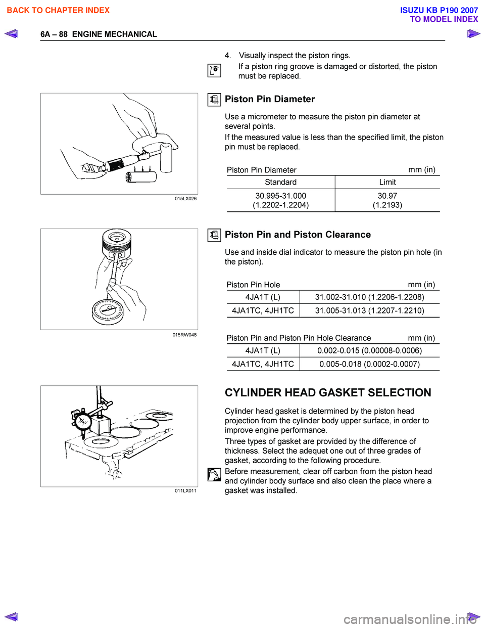
Piston Pin Diameter
Use a micrometer to measure the piston pin diameter at
several points.
If the measured value is less than the specified limit, the piston
pin must be replaced.
Piston Pin Diameter mm
(in)
Standard Limit
30.995-31.000
(1.2202-1.2204) 30.97
(1.2193)
Piston Pin and Piston Clearance
Use and inside dial indicator to measure the piston pin hole (in
the piston).
Piston Pin Hole mm
(in)
4JA1T (L) 31.002-31.010 (1.2206-1.2208)
4JA1TC, 4JH1TC 31.005-31.013 (1.2207-1.2210)
Piston Pin and Piston Pin Hole Clearance mm (in)
4JA1T (L) 0.002-0.015 (0.00008-0.0006)
4JA1TC, 4JH1TC 0.005-0.018 (0.0002-0.0007)
CYLINDER HEAD GASKET SELECTION
Cylinder head gasket is determined by the piston head
projection from the cylinder body upper surface, in order to
improve engine performance.
Three types of gasket are provided by the difference of
thickness. Select the adequet one out of three grades of
gasket, according to the following procedure.
Before measurement, clear off carbon from the piston head
and cylinder body surface and also clean the place where a
gasket was installed.
015LX026
015RW048
011LX011
BACK TO CHAPTER INDEX
TO MODEL INDEX
ISUZU KB P190 2007