body ISUZU KB P190 2007 Workshop Owners Manual
[x] Cancel search | Manufacturer: ISUZU, Model Year: 2007, Model line: KB P190, Model: ISUZU KB P190 2007Pages: 6020, PDF Size: 70.23 MB
Page 936 of 6020
ENGINE MECHANICAL 6A – 131
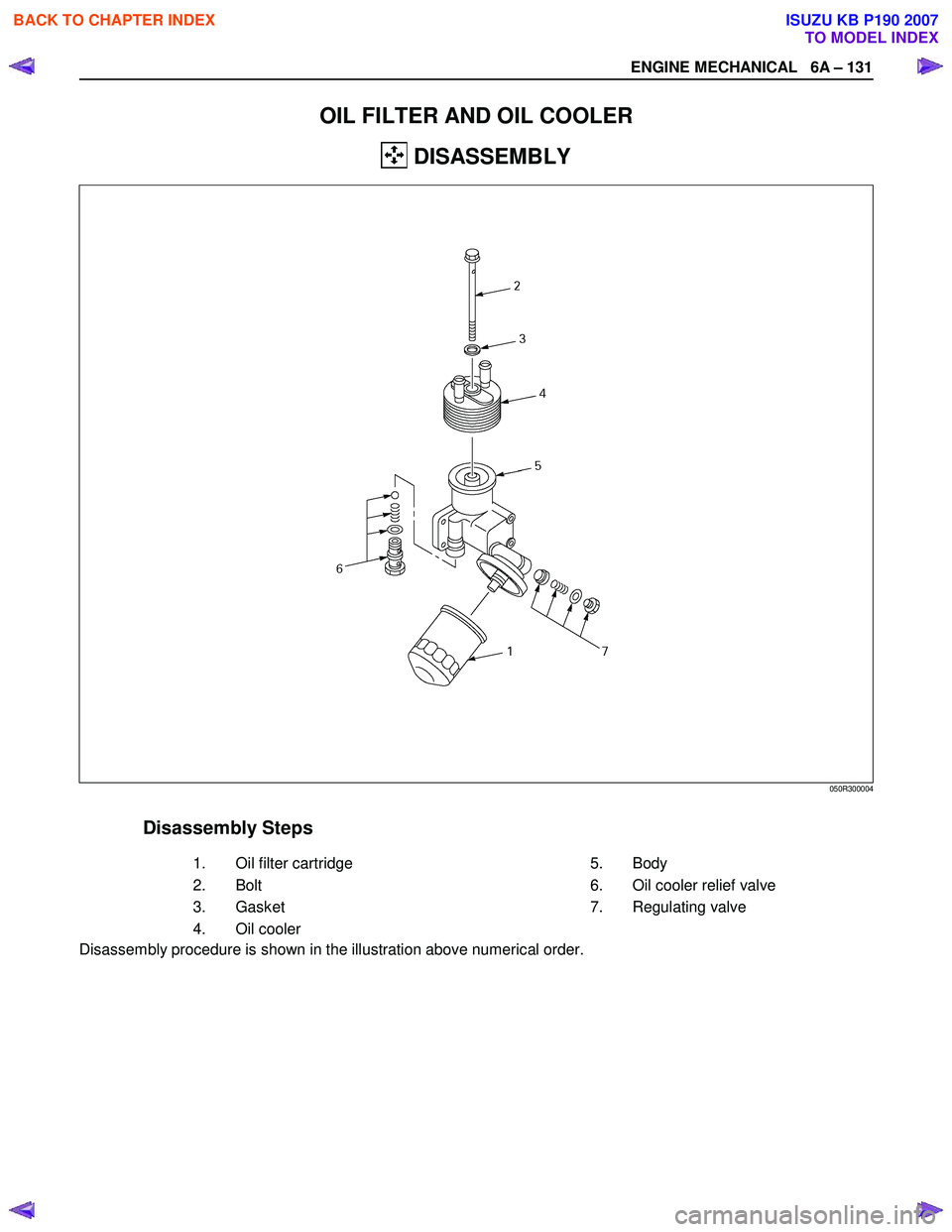
OIL FILTER AND OIL COOLER
DISASSEMBLY
Disassembly Steps
1.
Oil filter cartridge 5.
Body
2.
Bolt 6. Oil cooler relief valve
3. Gasket 7. Regulating valve
4. Oil cooler
Disassembly procedure is shown in the illustration above numerical order.
050R300004
BACK TO CHAPTER INDEX
TO MODEL INDEX
ISUZU KB P190 2007
Page 938 of 6020
ENGINE MECHANICAL 6A – 133
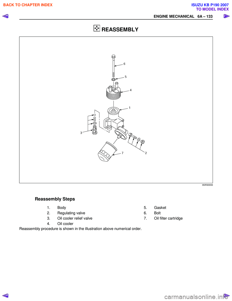
REASSEMBLY
Reassembly Steps
1.
Body 5.
Gasket
2.
Regulating valve 6. Bolt
3. Oil cooler relief valve 7. Oil filter cartridge
4. Oil cooler
Reassembly procedure is shown in the illustration above numerical order.
050R300003
BACK TO CHAPTER INDEX
TO MODEL INDEX
ISUZU KB P190 2007
Page 939 of 6020
6A – 134 ENGINE MECHANICAL
RTW 46ASH001701
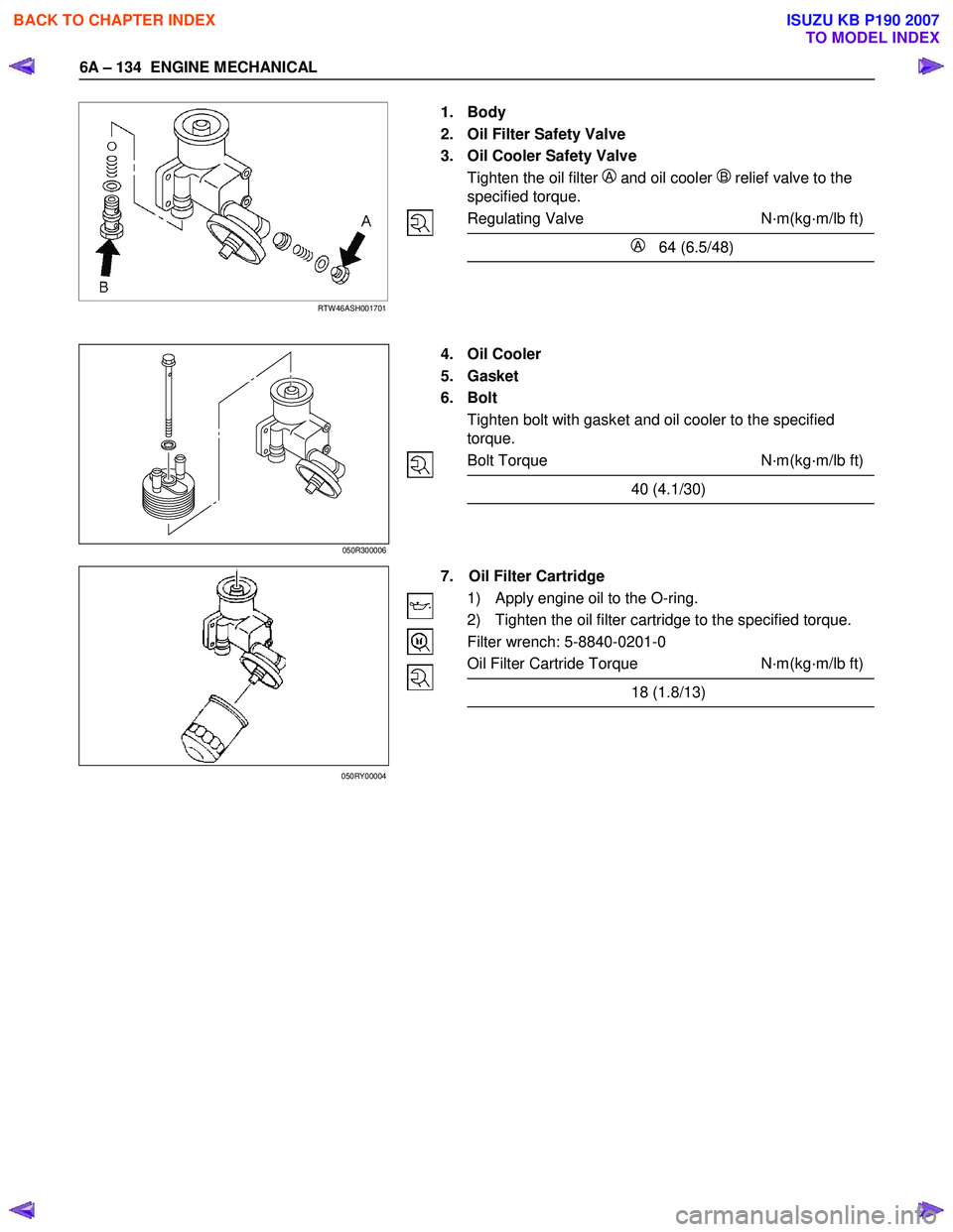
1. Body
2. Oil Filter Safety Valve
3. Oil Cooler Safety Valve
Tighten the oil filter
A and oil cooler B relief valve to the
specified torque.
Regulating Valve N·m(kg·m/lb ft)
A 64 (6.5/48)
4. Oil Cooler
5. Gasket
6. Bolt
Tighten bolt with gasket and oil cooler to the specified
torque.
Bolt Torque N·m(kg·m/lb ft)
40 (4.1/30)
7. Oil Filter Cartridge
1) Apply engine oil to the O-ring.
2) Tighten the oil filter cartridge to the specified torque.
Filter wrench: 5-8840-0201-0
Oil Filter Cartride Torque N·m(kg·m/lb ft)
18 (1.8/13)
050R300006
050RY00004
BACK TO CHAPTER INDEX
TO MODEL INDEX
ISUZU KB P190 2007
Page 948 of 6020

6B – 4 ENGINE COOLING
GENERAL DESCRIPTION
COOLANT FLOW
RTW 66ALF000101
The engine cooling system consists of the radiator, the water pump, the cooling fan, and the thermostat.
To quickly increase cold engine coolant temperature for smooth engine operation, the coolant is circulated by the
water pump and thermostat through the bypass hose and back to the cylinder body.
The coolant does not circulate through the radiator.
W hen the coolant temperature reaches specified value, the thermostat will begin to open and a gradually increasing
amount of coolant will circulate through the radiator.
The thermostat will be fully open when the coolant temperature reaches specified value. All of the coolant is now
circulating through the radiator for effective engine cooling.
BACK TO CHAPTER INDEX
TO MODEL INDEX
ISUZU KB P190 2007
Page 955 of 6020
ENGINE COOLING 6B – 11
Inspection and Repair
The water pump is not disassembled type.
Make necessary parts replacement if extreme wear or
damage is found during inspection. Should any of the
following problems occur, the entire water pump assembly
must be replaced.
・ Cracks in the water pump body
・ Coolant leakage from the seal unit
・ Excessive radial play or abnormal noise in the fan center
when rotate by hand
・ Excessive thrust play in the fan center (Standard play: less
than 0.2mm)
・ Cracks or corrosion in the impeller
Installation
1. Water Pump
1) Install the water pump with new gasket.
2) Tighten bolts and nuts to specified torque.
W ater Pump Bolt/Nut Torque N·m(kg·m/lb ft)
20 (2.0/14)
2. Fan Drive Belt and Pulley
1) Install the fan drive belt and fan pulley.
2) Apply tension to the fan drive belt by moving the generator.
3) Apply a force of 98N(10kg/22 lb) to the drive belt mid- portion to check the drive belt deflection.
Fan Drive Belt Deflection mm (in)
New belt: 4-7(0.16-0.28)
Reuse belt: 6-9(0.24-0.35)
030R300002
030R300001
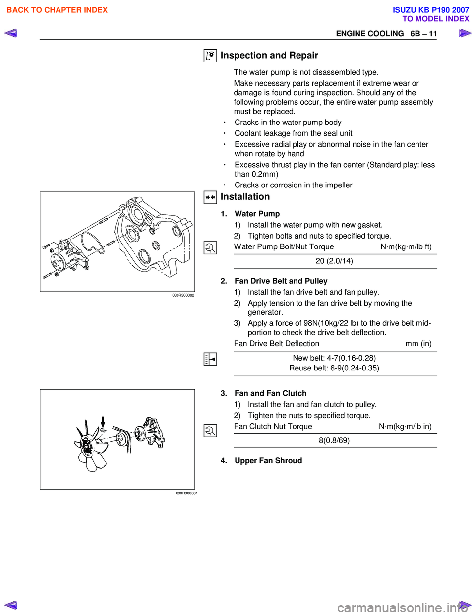
3. Fan and Fan Clutch
1) Install the fan and fan clutch to pulley.
2) Tighten the nuts to specified torque.
Fan Clutch Nut Torque N·m(kg·m/lb in)
8(0.8/69)
4. Upper Fan Shroud
BACK TO CHAPTER INDEX
TO MODEL INDEX
ISUZU KB P190 2007
Page 971 of 6020
FUEL SYSTEM 6C – 7
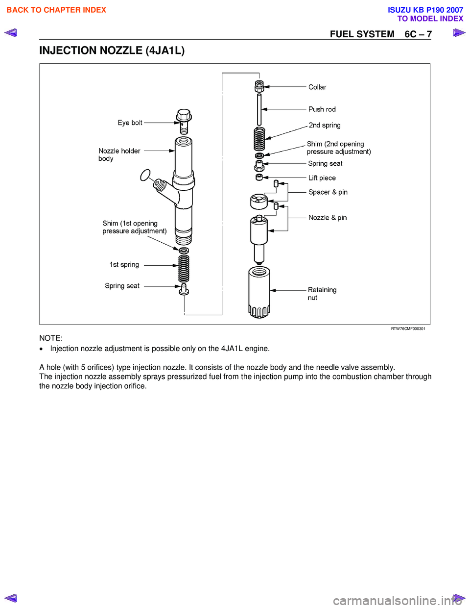
INJECTION NOZZLE (4JA1L)
RTW 76CMF000301
NOTE:
• Injection nozzle adjustment is possible only on the 4JA1L engine.
A hole (with 5 orifices) type injection nozzle. It consists of the nozzle body and the needle valve assembly.
The injection nozzle assembly sprays pressurized fuel from the injection pump into the combustion chamber through
the nozzle body injection orifice.
BACK TO CHAPTER INDEX
TO MODEL INDEX
ISUZU KB P190 2007
Page 973 of 6020
FUEL SYSTEM 6C – 9
Removal
CAUTION: When repair to the fuel system has been
completed, start engine and check the fuel system for
loose connection or leakage. For the fuel system
diagnosis, see Section “Driveability and Emission".
1. Disconnect battery ground cable.
2. Loosen slowly the fuel filler cap.
NOTE: Be careful not to spouting out fuel because of change
the pressure in the fuel tank.
NOTE: Cover opening of the filler neck to prevent any dust
entering.
3. Jack up the vehicle.
4. Support underneath of the fuel tank with a lifter.
5. Remove the inner liner of the wheel house at rear left side.
6. Remove fixing bolt of the filler neck from the body.
7. Disconnect the quick connector (3) of the fuel tube from the
fuel pipe.
NOTE: Cover the quick connector to prevent any dust entering
and fuel leakage.
NOTE: Refer to “Fuel Tube/Quick Connector Fittings” in this
section when performing any repairs.
8. Remove fixing bolt (1) of the tank band and remove the tank band (2).
9. Disconnect the pump and sender connector on the fuel
pump and remove the harness from weld clip on the fuel
tank.
10. Lower the fuel tank (5).
NOTE: W hen lower the fuel tank from the vehicle, don’t scratch
each hose and tube by around other parts.
Installation
1. Raise the fuel tank.
NOTE: W hen raise the fuel tank to the vehicle, don’t scratch
each hose and tube by around other parts.
2. Connect the pump and sender connector to the fuel pump and install the harness to weld clip on the tank.
NOTE: The connector must be certainly connected against
stopper.
3. Install the tank band and fasten bolt.
Torque N·m (kg·m / lb ft)
68 (6.9 / 50)
NOTE: The anchor of the tank band must be certainly installed
to guide hole on frame.
4. Connect the quick connector of the fuel tube to the fuel pipe and the evapo tube from evapo joint connector.
NOTE: Pull off the left checker on the fuel pipe.
NOTE: Refer to “Fuel Tube/Quick Connector Fittings” in this
section when performing any repairs.
BACK TO CHAPTER INDEX
TO MODEL INDEX
ISUZU KB P190 2007
Page 974 of 6020
6C – 10 FUEL SYSTEM
5. Install the filler neck to the body with bolt.
6. Install the inner liner of the wheel house at rear left side.
7. Remove lifter from the fuel tank.
8. Lower the vehicle.
9. Tigten the filler cap until at least three clicks.
10. Connect the battery ground cable.
BACK TO CHAPTER INDEX
TO MODEL INDEX
ISUZU KB P190 2007
Page 986 of 6020
6C – 22 FUEL SYSTEM
4JA1T (L)
RTW 46CSH000101
4JA1TC/4JH1TC
RTW 36AMH000101
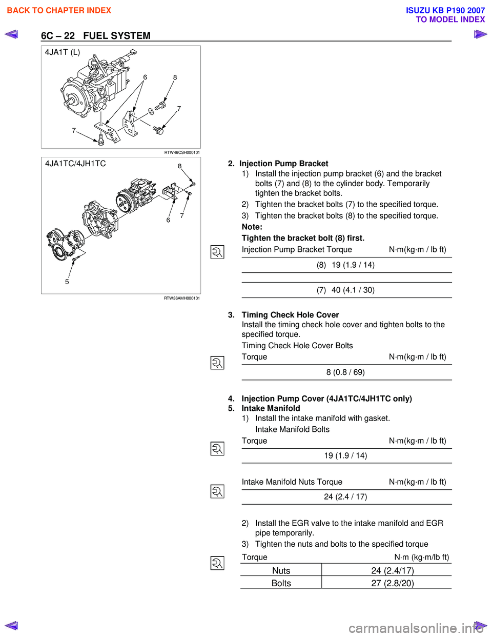
2. Injection Pump Bracket
1) Install the injection pump bracket (6) and the bracket bolts (7) and (8) to the cylinder body. Temporarily
tighten the bracket bolts.
2) Tighten the bracket bolts (7) to the specified torque.
3) Tighten the bracket bolts (8) to the specified torque.
Note:
Tighten the bracket bolt (8) first.
Injection Pump Bracket Torque N·m(kg·m / lb ft)
(8) 19 (1.9 / 14)
(7) 40 (4.1 / 30)
3. Timing Check Hole Cover
Install the timing check hole cover and tighten bolts to the
specified torque.
Timing Check Hole Cover Bolts
Torque N·m(kg·m / lb ft)
8 (0.8 / 69)
4. Injection Pump Cover (4JA1TC/4JH1TC only)
5. Intake Manifold
1) Install the intake manifold with gasket.
Intake Manifold Bolts
Torque N·m(kg·m / lb ft)
19 (1.9 / 14)
Intake Manifold Nuts Torque N·m(kg·m / lb ft)
24 (2.4 / 17)
2) Install the EGR valve to the intake manifold and EGR pipe temporarily.
3) Tighten the nuts and bolts to the specified torque
Torque N ⋅m (kg ⋅m/lb ft)
Nuts 24 (2.4/17)
Bolts 27 (2.8/20)
BACK TO CHAPTER INDEX
TO MODEL INDEX
ISUZU KB P190 2007
Page 989 of 6020
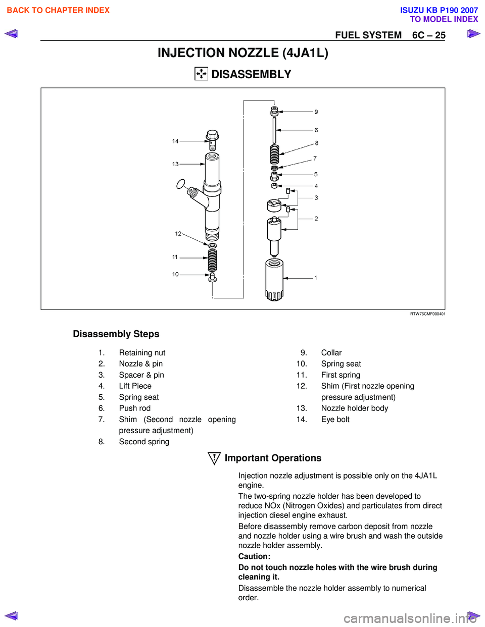
FUEL SYSTEM 6C – 25
INJECTION NOZZLE (4JA1L)
DISASSEMBLY
RTW 76CMF000401
Disassembly Steps
1. Retaining nut 2. Nozzle & pin
3. Spacer & pin
4. Lift Piece
5. Spring seat
6. Push rod
7. Shim (Second nozzle opening pressure adjustment)
8. Second spring 9. Collar
10. Spring seat
11. First spring
12. Shim (First nozzle opening pressure adjustment)
13. Nozzle holder body
14. Eye bolt
Important Operations
Injection nozzle adjustment is possible only on the 4JA1L
engine.
The two-spring nozzle holder has been developed to
reduce NOx (Nitrogen Oxides) and particulates from direct
injection diesel engine exhaust.
Before disassembly remove carbon deposit from nozzle
and nozzle holder using a wire brush and wash the outside
nozzle holder assembly.
Caution:
Do not touch nozzle holes with the wire brush during
cleaning it.
Disassemble the nozzle holder assembly to numerical
order.
BACK TO CHAPTER INDEX
TO MODEL INDEX
ISUZU KB P190 2007