body ISUZU KB P190 2007 Workshop Workshop Manual
[x] Cancel search | Manufacturer: ISUZU, Model Year: 2007, Model line: KB P190, Model: ISUZU KB P190 2007Pages: 6020, PDF Size: 70.23 MB
Page 829 of 6020
6A – 24 ENGINE MECHANICAL
SERVICING
Servicing refers to general maintenance procedures to be performed by qualified service personnel.
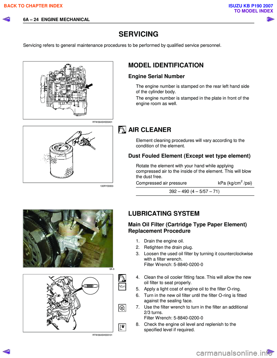
RTW 36ASH000401
MODEL IDENTIFICATION
Engine Serial Number
The engine number is stamped on the rear left hand side
of the cylinder body.
The engine number is stamped in the plate in front of the
engine room as well.
AIR CLEANER
Element cleaning procedures will vary according to the
condition of the element.
Dust Fouled Element (Except wet type element)
Rotate the element with your hand while applying
compressed air to the inside of the element. This will blow
the dust free.
Compressed air pressure kPa (kg/cm
2 /psi)
392 – 490 (4 – 5/57 – 71)
LUBRICATING SYSTEM
Main Oil Filter (Cartridge Type Paper Element)
Replacement Procedure
1. Drain the engine oil.
2. Retighten the drain plug.
3. Loosen the used oil filter by turning it counterclockwise with a filter wrench.
Filter W rench: 5-8840-0200-0
RTW 36ASH000101
4. Clean the oil cooler fitting face. This will allow the new oil filter to seat properly.
5. Apply a light coat of engine oil to the filter O-ring.
6. Turn in the new oil filter until the filter O-ring is fitted against the sealing face.
7. Use the filter wrench to turn in the filter an additional 2/3 turns.
Filter W rench: 5-8840-0200-0
8. Check the engine oil level and replenish to the specified level if required.
130RY00003
6A-6
BACK TO CHAPTER INDEX
TO MODEL INDEX
ISUZU KB P190 2007
Page 842 of 6020
ENGINE MECHANICAL 6A – 37
REMOVAL AND INSTALLATION
Read this section carefully before performing any removal and installation procedure. This section gives
you important points as well as the order of operation. Be sure that you understand everything in this section before
you begin.
Removal
P1010011
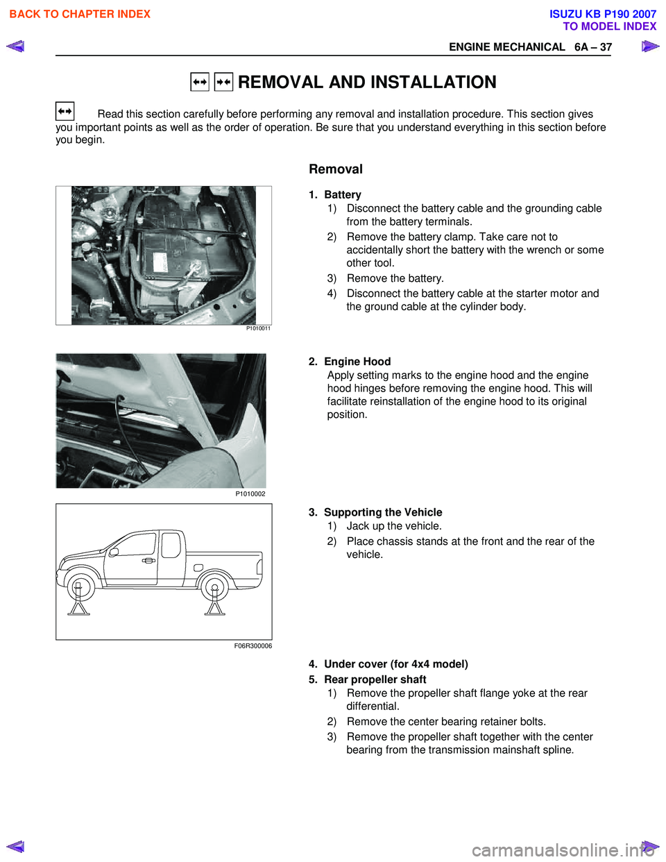
1. Battery
1) Disconnect the battery cable and the grounding cable from the battery terminals.
2) Remove the battery clamp. Take care not to accidentally short the battery with the wrench or some
other tool.
3) Remove the battery.
4) Disconnect the battery cable at the starter motor and the ground cable at the cylinder body.
2. Engine Hood Apply setting marks to the engine hood and the engine
hood hinges before removing the engine hood. This will
facilitate reinstallation of the engine hood to its original
position.
3. Supporting the Vehicle 1) Jack up the vehicle.
2) Place chassis stands at the front and the rear of the vehicle.
4. Under cover (for 4x4 model) 5. Rear propeller shaft 1) Remove the propeller shaft flange yoke at the rear differential.
2) Remove the center bearing retainer bolts.
3) Remove the propeller shaft together with the center bearing from the transmission mainshaft spline.
F06R300006 P1010002
BACK TO CHAPTER INDEX
TO MODEL INDEX
ISUZU KB P190 2007
Page 844 of 6020
ENGINE MECHANICAL 6A – 39
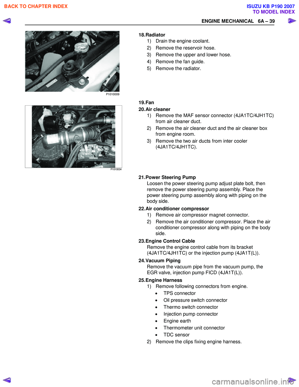
18. Radiator 1) Drain the engine coolant.
2) Remove the reservoir hose.
3) Remove the upper and lower hose.
4) Remove the fan guide.
5) Remove the radiator.
19. Fan
P1010034
20. Air cleaner
1) Remove the MAF sensor connector (4JA1TC/4JH1TC) from air cleaner duct.
2) Remove the air cleaner duct and the air cleaner box from engine room.
3) Remove the two air ducts from inter cooler (4JA1TC/4JH1TC).
21. Power Steering Pump Loosen the power steering pump adjust plate bolt, then
remove the power steering pump assembly. Place the
power steering pump assembly along with piping on the
body side.
22. Air conditioner compressor 1) Remove air compressor magnet connector.
2) Remove the air conditioner compressor. Place the air conditioner compressor along with piping on the body
side.
23. Engine Control Cable Remove the engine control cable from its bracket
(4JA1TC/4JH1TC) or the injection pump (4JA1T(L)).
24. Vacuum Piping Remove the vacuum pipe from the vacuum pump, the
EGR valve, injection pump FICD (4JA1T(L)).
25. Engine Harness 1) Remove following connectors from engine.
• TPS connector
• Oil pressure switch connector
• Thermo switch connector
• Injection pump connector
• Engine earth
• Thermometer unit connector
• TDC sensor
2) Remove the clips fixing engine harness.
P1010009
BACK TO CHAPTER INDEX
TO MODEL INDEX
ISUZU KB P190 2007
Page 848 of 6020
ENGINE MECHANICAL 6A – 43
ENGINE OVERHAUL
REMOVAL
EXTERNAL PARTS
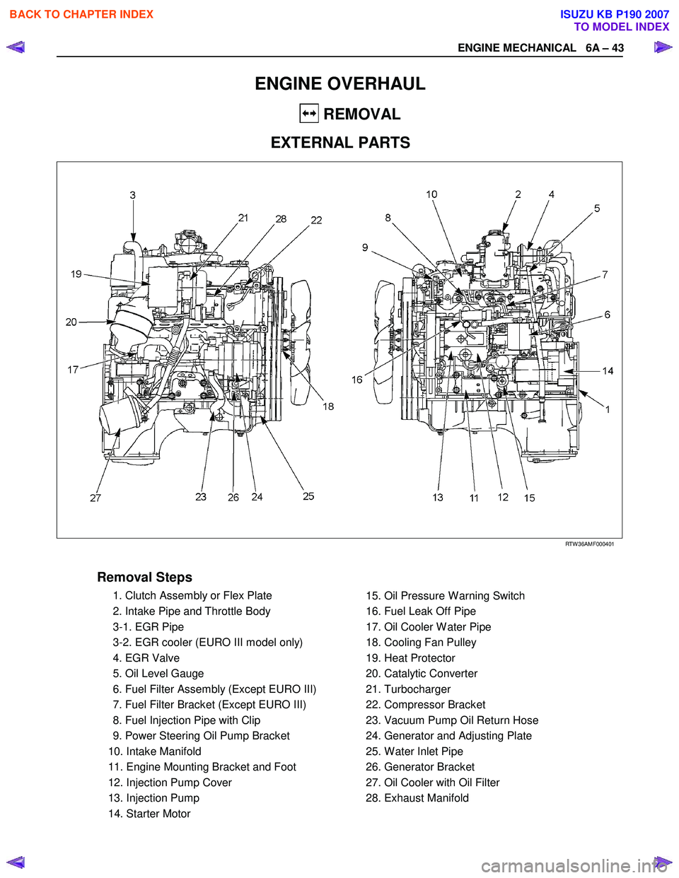
RTW 36AMF000401
Removal Steps
1. Clutch Assembly or Flex Plate
2. Intake Pipe and Throttle Body
3-1. EGR Pipe
3-2. EGR cooler (EURO III model only)
4. EGR Valve
5. Oil Level Gauge
6. Fuel Filter Assembly (Except EURO III)
7. Fuel Filter Bracket (Except EURO III)
8. Fuel Injection Pipe with Clip
9. Power Steering Oil Pump Bracket
10. Intake Manifold
11. Engine Mounting Bracket and Foot
12. Injection Pump Cover
13. Injection Pump
14. Starter Motor
15. Oil Pressure W arning Switch
16. Fuel Leak Off Pipe
17. Oil Cooler W ater Pipe
18. Cooling Fan Pulley
19. Heat Protector
20. Catalytic Converter
21. Turbocharger
22. Compressor Bracket
23. Vacuum Pump Oil Return Hose
24. Generator and Adjusting Plate
25. W ater Inlet Pipe
26. Generator Bracket
27. Oil Cooler with Oil Filter
28. Exhaust Manifold
BACK TO CHAPTER INDEX
TO MODEL INDEX
ISUZU KB P190 2007
Page 849 of 6020
6A – 44 ENGINE MECHANICAL
Removal
1. Clutch Assembly or Flex Plate
Remove the clutch assembly or the flex plate.
4JA1L RTW 46ASH000801
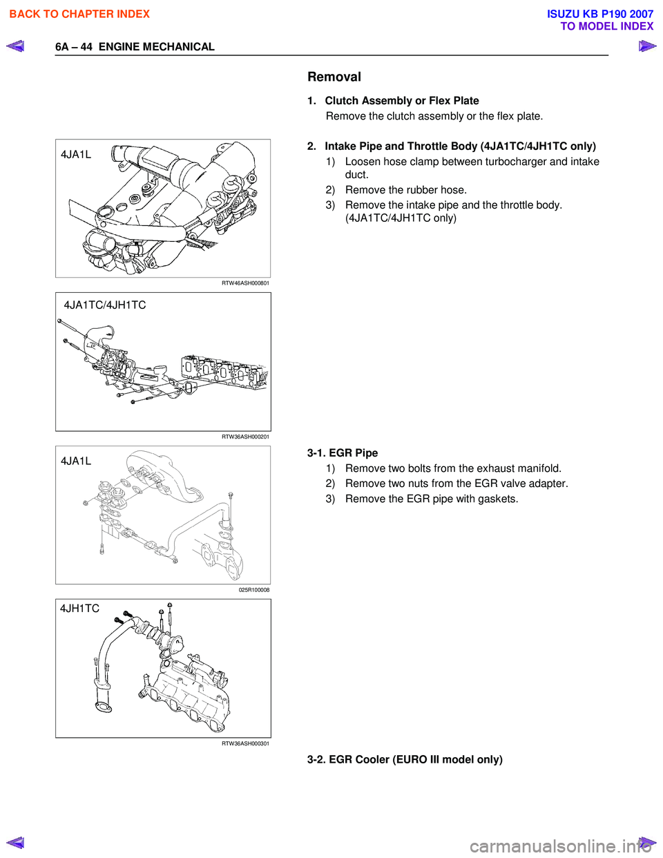
2. Intake Pipe and Throttle Body (4JA1TC/4JH1TC only)
1) Loosen hose clamp between turbocharger and intake duct.
2) Remove the rubber hose.
3) Remove the intake pipe and the throttle body. (4JA1TC/4JH1TC only)
RTW 36ASH000201
4JA1L
025R100008
3-1. EGR Pipe
1) Remove two bolts from the exhaust manifold.
2) Remove two nuts from the EGR valve adapter.
3) Remove the EGR pipe with gaskets.
RTW 36ASH000301
3-2. EGR Cooler (EURO III model only)
4JA1TC/4JH1TC
4JH1TC
BACK TO CHAPTER INDEX
TO MODEL INDEX
ISUZU KB P190 2007
Page 851 of 6020
6A – 46 ENGINE MECHANICAL
13. Injection Pump
Refer to section 6C-19 (Injection Pump)
14. Starter Motor
15. Oil Pressure Warning Switch
16. Fuel Leak Off Pipe
17. Oil Cooler Water Pipe
18. Cooling Fan Pulley
19. Heat Protector
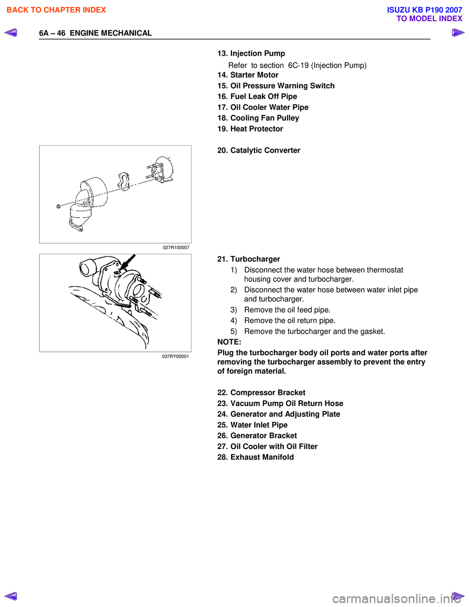
20. Catalytic Converter
21. Turbocharger 1) Disconnect the water hose between thermostat housing cover and turbocharger.
2) Disconnect the water hose between water inlet pipe and turbocharger.
3) Remove the oil feed pipe.
4) Remove the oil return pipe.
5) Remove the turbocharger and the gasket.
NOTE:
Plug the turbocharger body oil ports and water ports after
removing the turbocharger assembly to prevent the entry
of foreign material.
22. Compressor Bracket
23. Vacuum Pump Oil Return Hose
24. Generator and Adjusting Plate
25. Water Inlet Pipe
26. Generator Bracket
27. Oil Cooler with Oil Filter
28. Exhaust Manifold
027R100007
037RY00001
BACK TO CHAPTER INDEX
TO MODEL INDEX
ISUZU KB P190 2007
Page 854 of 6020
ENGINE MECHANICAL 6A – 49
014R300005
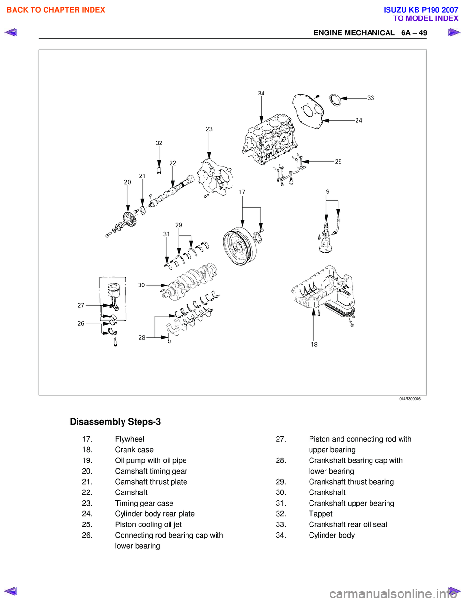
Disassembly Steps-3
17. Flywheel 27. Piston and connecting rod with
18. Crank case upper bearing
19. Oil pump with oil pipe 28. Crankshaft bearing cap with
20. Camshaft timing gear lower bearing
21. Camshaft thrust plate 29. Crankshaft thrust bearing
22. Camshaft 30. Crankshaft
23. Timing gear case 31. Crankshaft upper bearing
24. Cylinder body rear plate 32. Tappet
25. Piston cooling oil jet 33. Crankshaft rear oil seal
26. Connecting rod bearing cap with 34. Cylinder body
lower bearing
BACK TO CHAPTER INDEX
TO MODEL INDEX
ISUZU KB P190 2007
Page 858 of 6020
ENGINE MECHANICAL 6A – 53
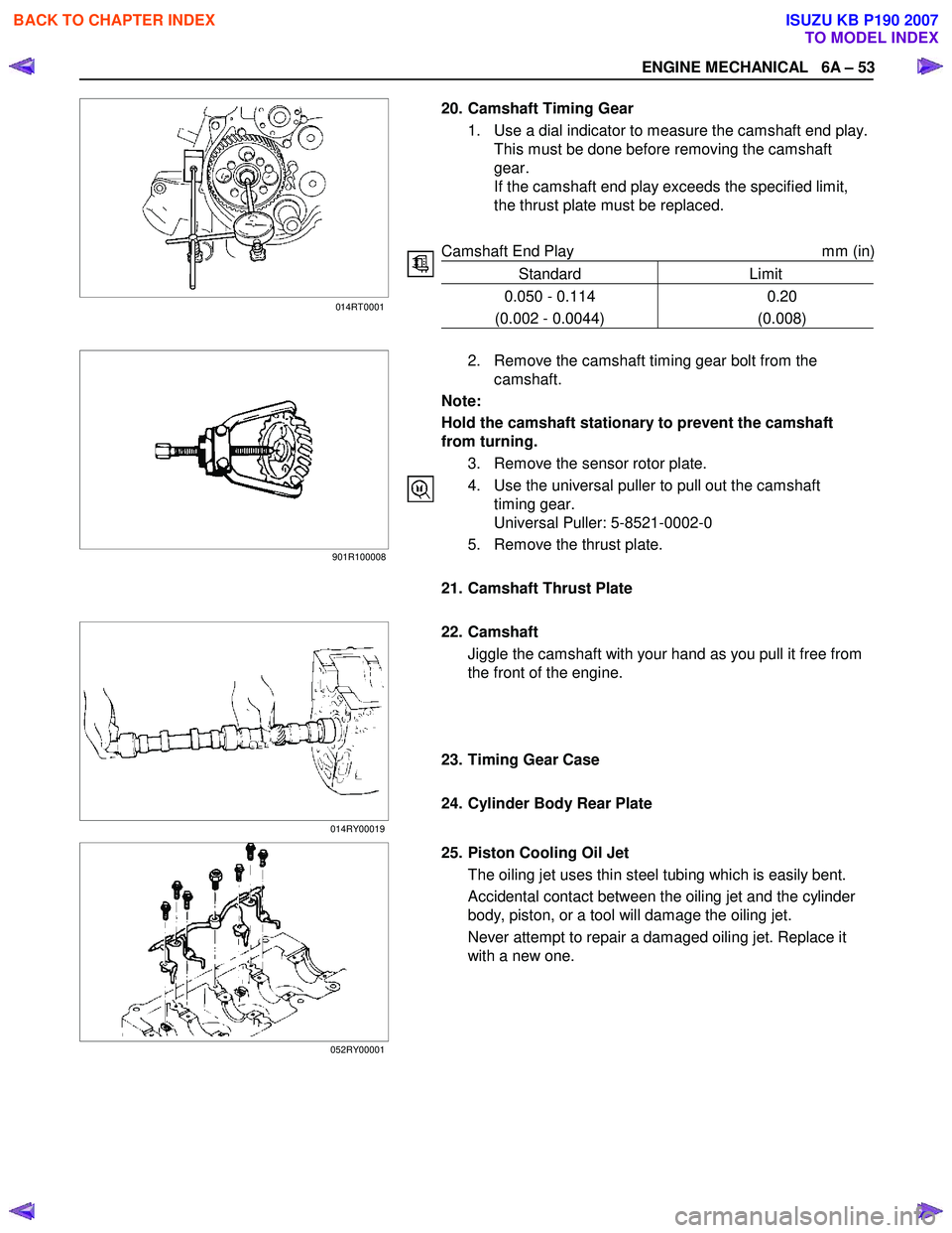
20. Camshaft Timing Gear
1. Use a dial indicator to measure the camshaft end play.This must be done before removing the camshaft
gear.
If the camshaft end play exceeds the specified limit,
the thrust plate must be replaced.
Camshaft End Play mm (in)
Standard Limit
0.050 - 0.114
(0.002 - 0.0044) 0.20
(0.008)
2. Remove the camshaft timing gear bolt from the
camshaft.
Note:
Hold the camshaft stationary to prevent the camshaft
from turning.
3. Remove the sensor rotor plate.
4. Use the universal puller to pull out the camshaft timing gear.
Universal Puller: 5-8521-0002-0
5. Remove the thrust plate.
21. Camshaft Thrust Plate
22. Camshaft
Jiggle the camshaft with your hand as you pull it free from
the front of the engine.
23. Timing Gear Case
24. Cylinder Body Rear Plate
25. Piston Cooling Oil Jet The oiling jet uses thin steel tubing which is easily bent.
Accidental contact between the oiling jet and the cylinder
body, piston, or a tool will damage the oiling jet.
Never attempt to repair a damaged oiling jet. Replace it
with a new one.
014RT0001
901R100008
014RY00019
052RY00001
BACK TO CHAPTER INDEX
TO MODEL INDEX
ISUZU KB P190 2007
Page 860 of 6020
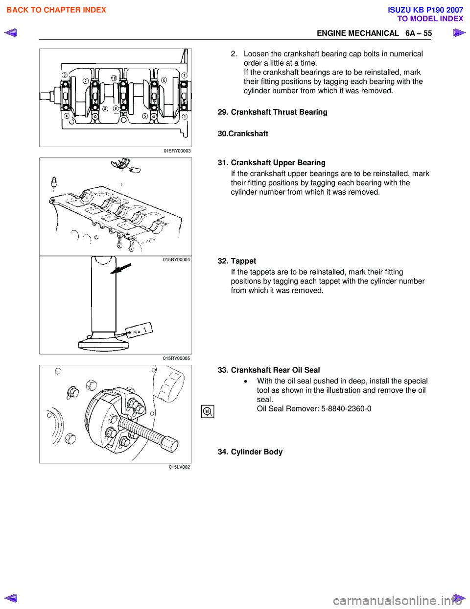
ENGINE MECHANICAL 6A – 55
2. Loosen the crankshaft bearing cap bolts in numerical order a little at a time.
If the crankshaft bearings are to be reinstalled, mark
their fitting positions by tagging each bearing with the
cylinder number from which it was removed.
29. Crankshaft Thrust Bearing
30.Crankshaft
31. Crankshaft Upper Bearing If the crankshaft upper bearings are to be reinstalled, mark
their fitting positions by tagging each bearing with the
cylinder number from which it was removed.
32. Tappet
If the tappets are to be reinstalled, mark their fitting
positions by tagging each tappet with the cylinder number
from which it was removed.
33. Crankshaft Rear Oil Seal
• W ith the oil seal pushed in deep, install the special
tool as shown in the illustration and remove the oil
seal.
Oil Seal Remover: 5-8840-2360-0
34. Cylinder Body
015RY00003
015RY00004
015RY00005
015LV002
BACK TO CHAPTER INDEX
TO MODEL INDEX
ISUZU KB P190 2007
Page 874 of 6020

ENGINE MECHANICAL 6A – 69
3. Check that the rocker arm oil port is free of obstructions. If necessary, use compressed air to clean the rocker arm
oil port.
Rocker Arm Correction
Inspect the rocker arm valve stem contact surfaces for step
wear (1) and scoring (2).
If the contact surfaces have light step wear or scoring, they
may be honed with an oil stone.
If the step wear or scoring is severe, the rocker arm must be
replaced.
CYLINDER BODY
Cylinder Body Upper Face Warpage
1. Remove the cylinder body dowel.
2. Remove the cylinder liner. Refer to "Cylinder Liner Replacement".
3. Use a straight edge (1) and a feeler gauge (2) to measure
the four sides and the two diagonals of the cylinder body
upper face.
If the measured values exceeds the limit, the cylinder body
must be replaced.
Cylinder Body Upper Face Warpage mm (in)
Standard Limit
0.05 (0.002) or less 0.20 (0.008)
Cylinder Body Height (H) (Reference) mm (in)
Standard
4JA1T(L), 4JA1TC : 244.945-245.055 (9.6435-9.6478)
4JH1TC : 269.945-270.055 (10.6277-10.6320)
4. Reinstall the cylinder liner. Refer to "Cylinder Liner Replacement".
5. Reinstall the cylinder body dowel.
014RY00024
012R100001
012RY00009 014RY00023
BACK TO CHAPTER INDEX
TO MODEL INDEX
ISUZU KB P190 2007