oil filter ISUZU KB P190 2007 Workshop Manual PDF
[x] Cancel search | Manufacturer: ISUZU, Model Year: 2007, Model line: KB P190, Model: ISUZU KB P190 2007Pages: 6020, PDF Size: 70.23 MB
Page 2403 of 6020
ENGINE DRIVEABILITY AND EMISSIONS 6E–233
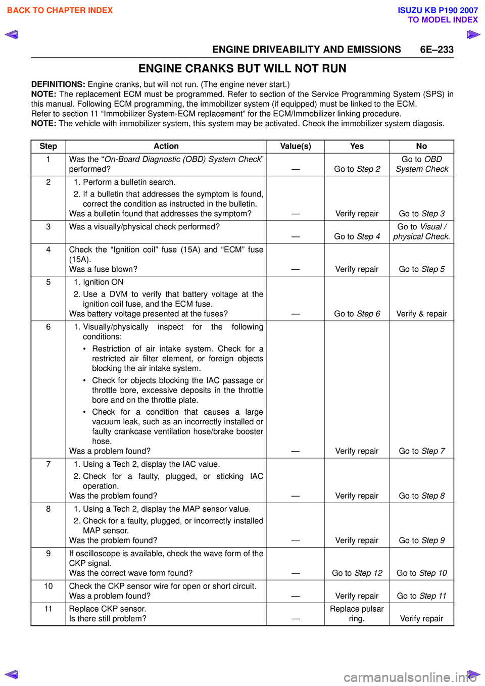
ENGINE CRANKS BUT WILL NOT RUN
DEFINITIONS: Engine cranks, but will not run. (The engine never start.)
NOTE: The replacement ECM must be programmed. Refer to section of the Service Programming System (SPS) in
this manual. Following ECM programming, the immobilizer system (if equipped) must be linked to the ECM.
Refer to section 11 “Immobilizer System-ECM replacement” for the ECM/Immobilizer linking procedure.
NOTE: The vehicle with immobilizer system, this system may be activated. Check the immobilizer system diagosis.
Step Action Value(s) Yes No
1 Was the “ On-Board Diagnostic (OBD) System Check ”
performed? — Go to Step 2Go to
OBD
System Check
2 1. Perform a bulletin search. 2. If a bulletin that addresses the symptom is found,correct the condition as instructed in the bulletin.
Was a bulletin found that addresses the symptom? — Verify repair Go to Step 3
3 Was a visually/physical check performed? —Go to Step 4Go to
Visual /
physical Check.
4 Check the “Ignition coil” fuse (15A) and “ECM” fuse (15A).
Was a fuse blown? — Verify repair Go to Step 5
5 1. Ignition ON 2. Use a DVM to verify that battery voltage at theignition coil fuse, and the ECM fuse.
Was battery voltage presented at the fuses? — Go to Step 6Verify & repair
6 1. Visually/physically inspect for the following conditions:
• Restriction of air intake system. Check for a restricted air filter element, or foreign objects
blocking the air intake system.
• Check for objects blocking the IAC passage or throttle bore, excessive deposits in the throttle
bore and on the throttle plate.
• Check for a condition that causes a large vacuum leak, such as an incorrectly installed or
faulty crankcase ventilation hose/brake booster
hose.
Was a problem found? — Verify repair Go to Step 7
7 1. Using a Tech 2, display the IAC value. 2. Check for a faulty, plugged, or sticking IACoperation.
Was the problem found? — Verify repair Go to Step 8
8 1. Using a Tech 2, display the MAP sensor value. 2. Check for a faulty, plugged, or incorrectly installedMAP sensor.
Was the problem found? — Verify repair Go to Step 9
9 If oscilloscope is available, check the wave form of the CKP signal.
Was the correct wave form found? — Go to Step 12Go to Step 10
10 Check the CKP sensor wire for open or short circuit. Was a problem found? — Verify repair Go to Step 11
11 Replace CKP sensor. Is there still problem? —Replace pulsar
ring. Verify repair
BACK TO CHAPTER INDEX
TO MODEL INDEX
ISUZU KB P190 2007
Page 2419 of 6020
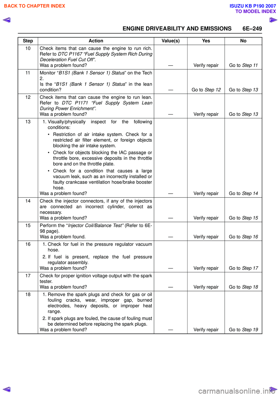
ENGINE DRIVEABILITY AND EMISSIONS 6E–249
10 Check items that can cause the engine to run rich.Refer to DTC P1167 “Fuel Supply System Rich During
Deceleration Fuel Cut Off” .
Was a problem found? — Verify repair Go to Step 11
11 Monitor “ B1S1 (Bank 1 Sensor 1) Status ” on the Tech
2.
Is the “ B1S1 (Bank 1 Sensor 1) Status ” in the lean
condition? — Go to Step 12Go to Step 13
12 Check items that can cause the engine to run lean. Refer to DTC P1171 “Fuel Supply System Lean
During Power Enrichment” .
Was a problem found? — Verify repair Go to Step 13
13 1. Visually/physically inspect for the following conditions:
• Restriction of air intake system. Check for a restricted air filter element, or foreign objects
blocking the air intake system.
• Check for objects blocking the IAC passage or throttle bore, excessive deposits in the throttle
bore and on the throttle plate.
• Check for a condition that causes a large vacuum leak, such as an incorrectly installed or
faulty crankcase ventilation hose/brake booster
hose.
Was a problem found? — Verify repair Go to Step 14
14 Check the injector connectors, if any of the injectors are connected an incorrect cylinder, correct as
necessary.
Was a problem found? — Verify repair Go to Step 15
15 Perform the “ Injector Coil/Balance Test” (Refer to 6E-
98 page).
Was a problem found. — Verify repair Go to Step 16
16 1. Check for fuel in the pressure regulator vacuum hose.
2. If fuel is present, replace the fuel pressure regulator assembly.
Was a problem found? — Verify repair Go to Step 17
17 Check for proper ignition voltage output with the spark tester.
Was a problem found? — Verify repair Go to Step 18
18 1. Remove the spark plugs and check for gas or oil fouling cracks, wear, improper gap, burned
electrodes, heavy deposits, or improper heat
range.
2. If spark plugs are fouled, the cause of fouling must be determined before replacing the spark plugs.
Was a problem found? — Verify repair Go to Step 19
Step
Action Value(s) Yes No
BACK TO CHAPTER INDEX
TO MODEL INDEX
ISUZU KB P190 2007
Page 2442 of 6020
6E–272 ENGINE DRIVEABILITY AND EMISSIONS
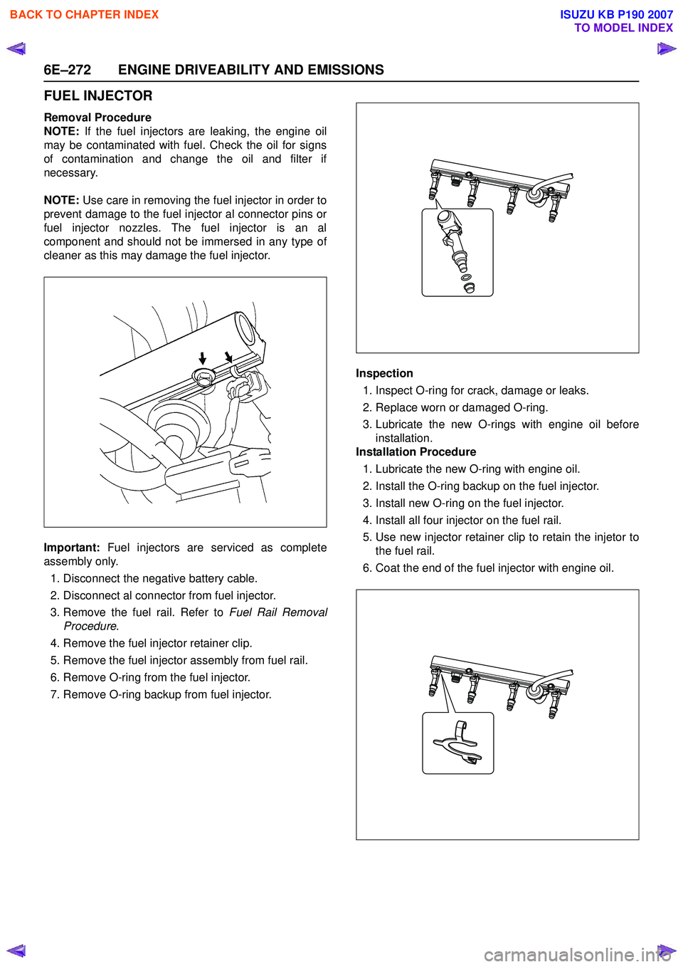
FUEL INJECTOR
Removal Procedure
NOTE: If the fuel injectors are leaking, the engine oil
may be contaminated with fuel. Check the oil for signs
of contamination and change the oil and filter if
necessary.
NOTE: Use care in removing the fuel injector in order to
prevent damage to the fuel injector al connector pins or
fuel injector nozzles. The fuel injector is an al
component and should not be immersed in any type of
cleaner as this may damage the fuel injector.
Important: Fuel injectors are serviced as complete
assembly only.
1. Disconnect the negative battery cable.
2. Disconnect al connector from fuel injector.
3. Remove the fuel rail. Refer to Fuel Rail Removal
Procedure .
4. Remove the fuel injector retainer clip.
5. Remove the fuel injector assembly from fuel rail.
6. Remove O-ring from the fuel injector.
7. Remove O-ring backup from fuel injector. Inspection
1. Inspect O-ring for crack, damage or leaks.
2. Replace worn or damaged O-ring.
3. Lubricate the new O-rings with engine oil before installation.
Installation Procedure
1. Lubricate the new O-ring with engine oil.
2. Install the O-ring backup on the fuel injector.
3. Install new O-ring on the fuel injector.
4. Install all four injector on the fuel rail.
5. Use new injector retainer clip to retain the injetor to the fuel rail.
6. Coat the end of the fuel injector with engine oil.
BACK TO CHAPTER INDEX
TO MODEL INDEX
ISUZU KB P190 2007
Page 2466 of 6020
6G-2 ENGINE LUBRICATION
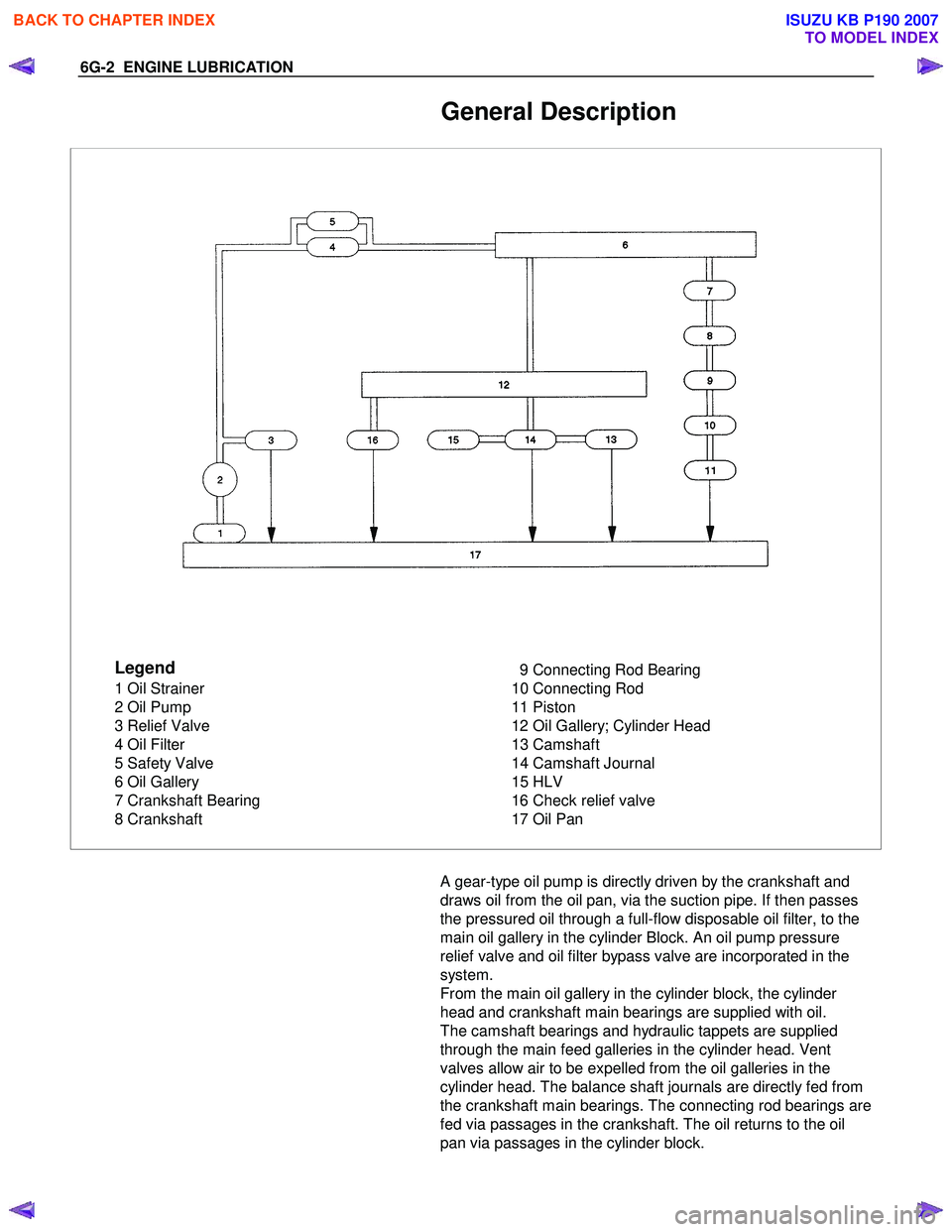
General Description
Legend
1 Oil Strainer
2 Oil Pump
3 Relief Valve
4 Oil Filter
5 Safety Valve
6 Oil Gallery
7 Crankshaft Bearing
8 Crankshaft 9 Connecting Rod Bearing
10 Connecting Rod
11 Piston
12 Oil Gallery; Cylinder Head
13 Camshaft
14 Camshaft Journal
15 HLV
16 Check relief valve
17 Oil Pan
A gear-type oil pump is directly driven by the crankshaft and
draws oil from the oil pan, via the suction pipe. If then passes
the pressured oil through a full-flow disposable oil filter, to the
main oil gallery in the cylinder Block. An oil pump pressure
relief valve and oil filter bypass valve are incorporated in the
system.
From the main oil gallery in the cylinder block, the cylinder
head and crankshaft main bearings are supplied with oil.
The camshaft bearings and hydraulic tappets are supplied
through the main feed galleries in the cylinder head. Vent
valves allow air to be expelled from the oil galleries in the
cylinder head. The balance shaft journals are directly fed from
the crankshaft main bearings. The connecting rod bearings are
fed via passages in the crankshaft. The oil returns to the oil
pan via passages in the cylinder block.
BACK TO CHAPTER INDEX
TO MODEL INDEX
ISUZU KB P190 2007
Page 2471 of 6020
ENGINE LUBRICATION 6G-7
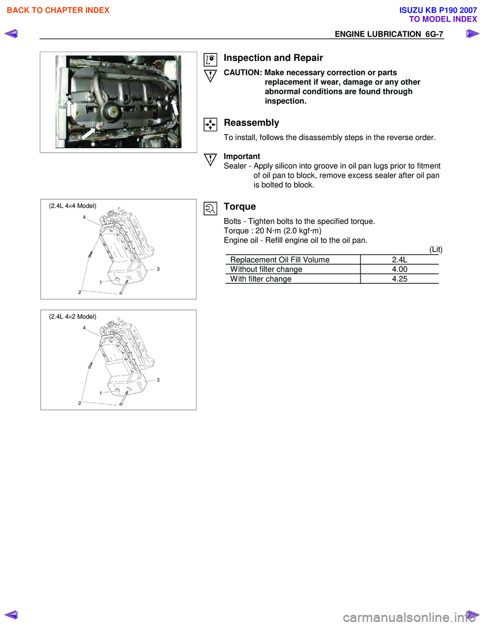
Inspection and Repair
CAUTION: Make necessary correction or parts replacement if wear, damage or any other
abnormal conditions are found through
inspection.
Reassembly
To install, follows the disassembly steps in the reverse order.
Important
Sealer - Apply silicon into groove in oil pan lugs prior to fitment of oil pan to block, remove excess sealer after oil pan
is bolted to block.
(2.4L 4 ×4 Model)
4
3
1
2
(2.4L 4 ×2 Model)
4
3
1
2
Torque
Bolts - Tighten bolts to the specified torque.
Torque : 20 N �xm (2.0 kgf �xm)
Engine oil - Refill engine oil to the oil pan. (Lit)
Replacement Oil Fill Volume 2.4L
W ithout filter change 4.00
W ith filter change 4.25
BACK TO CHAPTER INDEX
TO MODEL INDEX
ISUZU KB P190 2007
Page 2480 of 6020
Engine Mechanical – V6 Page 6A1–1
6A1
Engine Mechanical – V6
ATTENTION
Before performing any service operation or other procedure described in this Section, refer to 1.1
WARNING, CAUTION and NOTES for correct workshop practices with regard to safety and/or property
damage.
1 General Information ............................................................................................................ ...................8
1.1 WARNING, CAUTION and NOTES .................................................................................................... ................... 8
Definition of WARNING, CAUTION and NOTE Statements ............................................................................. .... 8
WARNING defined ............................................................................................................................................. 8
CAUTION defined .............................................................................................................................................. 8
NOTE defined..................................................................................................................................................... 9
1.2 Engine Components .............................................................................................................................................. 9
Major Component Assemblies..................................................................................................... ......................... 9
Intake Manifold Assembly ................................................................................................................................... 10
Engine Front Cover.............................................................................................................................................. 12
Camshaft Timing Components ..................................................................................................... ...................... 13
Camshaft Cover Assembly.................................................................................................................................. 14
Cylinder Head Assembly ..................................................................................................................................... 15
Oil Pump ............................................................................................................................................................... 16
Engine Block Assembly .......................................................................................................... ............................ 17
Pistons, Rings, Bearing and Connecting Rod ..................................................................................... .............. 18
Oil Pan Assembly................................................................................................................................................. 19
Oil Filter Assembly .............................................................................................................................................. 20
1.3 Engine Serial Number........................................................................................................... ............................... 20
1.4 Engine Construction............................................................................................................................................ 21
Cylinder Block ...................................................................................................................................................... 21
Cylinder Heads ................................................................................................................. .................................... 21
Crankshaft ............................................................................................................................................................ 22
Pistons, Pins and Connecting Rods .............................................................................................. .................... 22
Camshaft Drive System ....................................................................................................................................... 22
1.5 Engine Lubrication System ...................................................................................................... ........................... 24
Lubrication Description....................................................................................................................................... 24
1.6 Service Notes ....................................................................................................................................................... 24
Cleanliness and Care........................................................................................................... ................................ 24
Replacing Engine Gaskets ....................................................................................................... ........................... 24
Re-Using Gaskets and Applying Sealants......................................................................................... ............... 24
Separating Components................................................................................................................................... 24
Cleaning Gasket Surfaces................................................................................................................................ 24
Assembling Components .......................................................................................................... ....................... 25
Use of Room Temperature Vulcanising and Anaerobic Sealer....................................................................... .25
Room Temperature Vulcanising Sealer............................................................................................................ 25
Anaerobic Sealer .............................................................................................................................................. 25
Pipe Joint Compound ............................................................................................................ ........................... 26
Separating Parts .................................................................................................................................................. 26
Tools and Equipment ............................................................................................................ .............................. 26
Fasteners .............................................................................................................................................................. 27
Clamp Load ..................................................................................................................... ................................. 27
Torque Angle and Torque to Yield Fasteners..................................................................................... .............. 27
2 Diagnosis ..............................................................................................................................................28
2.1 Engine Diagnosis ............................................................................................................... .................................. 28
2.2 Symptoms............................................................................................................................................................. 28
Strategy Based Diagnosis ....................................................................................................... ............................ 28
BACK TO CHAPTER INDEX
TO MODEL INDEX
ISUZU KB P190 2007
Page 2482 of 6020
Engine Mechanical – V6 Page 6A1–3
Definition .......................................................................................................................................................... 50
Diagnostic Aids................................................................................................................................................. 50
Test Description ............................................................................................................... ................................ 50
Diagnostic Table............................................................................................................................................... 51
Drive Belt Excessive Wear ...................................................................................................... ............................ 51
Definition .......................................................................................................................................................... 51
Diagnostic Aids................................................................................................................................................. 52
Test Description ............................................................................................................... ................................ 52
Diagnostic Table............................................................................................................................................... 52
Accessory Drive Belt Tensioner Diagnosis ....................................................................................... ................ 52
Diagnostic Table............................................................................................................................................... 52
3 Minor Service Operations ....................................................................................................... .............53
3.1 Engine Oil ............................................................................................................................................................. 54
Check .................................................................................................................................................................... 54
Replace ........................................................................................................................ ......................................... 54
Pressure Check ................................................................................................................. ................................... 55
3.2 Oil Filter Cartridge ............................................................................................................................................... 56
Replace ................................................................................................................................................................. 56
3.3 Oil Filter Adaptor............................................................................................................. ..................................... 57
Remove ................................................................................................................................................................. 57
Reinstall ................................................................................................................................................................ 57
3.4 Oil Level Indicator Tube ....................................................................................................... ............................... 58
Remove ............................................................................................................................................................ 58
Reinstall ........................................................................................................................................................... 58
3.5 Accessory Drive Belt ........................................................................................................... ................................ 59
RWD Vehicle ......................................................................................................................................................... 59
Remove ............................................................................................................................................................ 59
Reinstall ........................................................................................................................................................... 59
3.6 Accessory Drive Belt Idler Pulley .............................................................................................. ......................... 60
Remove ............................................................................................................................................................ 60
Reinstall ........................................................................................................................................................... 60
3.7 Accessory Drive Belt Tensioner Assembly ........................................................................................ ............... 61
Remove ............................................................................................................................................................ 61
Reinstall ........................................................................................................................................................... 61
3.8 Power Steering Pump Bracket .................................................................................................... ........................ 62
Remove ................................................................................................................................................................. 62
Reinstall ................................................................................................................................................................ 62
3.9 Upper Intake Manifold.......................................................................................................... ................................ 62
Remove ................................................................................................................................................................. 63
Disassemble ......................................................................................................................................................... 66
Clean ..................................................................................................................................................................... 66
Inspect .................................................................................................................................................................. 66
Reassemble .......................................................................................................................................................... 67
Reinstall ...................................................................................................................... .......................................... 67
3.10 Intake Manifold Assembly – Complete............................................................................................ ................... 68
Remove ................................................................................................................................................................. 68
Disassemble ......................................................................................................................................................... 72
Clean ..................................................................................................................................................................... 73
Inspect .................................................................................................................................................................. 73
Reassemble .......................................................................................................................................................... 74
Reinstall ...................................................................................................................... .......................................... 74
3.11 Exhaust Manifold Assembly ...................................................................................................... ......................... 75
Remove ................................................................................................................................................................. 75
Inspect .................................................................................................................................................................. 77
Reinstall ................................................................................................................................................................ 77
3.12 Camshaft Cover ................................................................................................................. .................................. 79
Remove ................................................................................................................................................................. 79
Clean and Inspect .............................................................................................................. .................................. 81
BACK TO CHAPTER INDEX
TO MODEL INDEX
ISUZU KB P190 2007
Page 2499 of 6020
Engine Mechanical – V6 Page 6A1–20
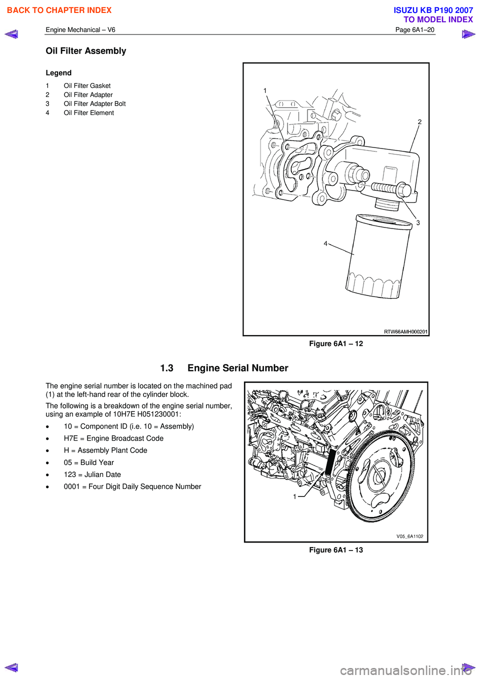
Oil Filter Assembly
Legend
1 Oil Filter Gasket
2 Oil Filter Adapter
3 Oil Filter Adapter Bolt
4 Oil Filter Element
Figure 6A1 – 12
1.3 Engine Serial Number
The engine serial number is located on the machined pad
(1) at the left-hand rear of the cylinder block.
The following is a breakdown of the engine serial number,
using an example of 10H7E H051230001:
• 10 = Component ID (i.e. 10 = Assembly)
• H7E = Engine Broadcast Code
• H = Assembly Plant Code
• 05 = Build Year
• 123 = Julian Date
• 0001 = Four Digit Daily Sequence Number
Figure 6A1 – 13
BACK TO CHAPTER INDEX
TO MODEL INDEX
ISUZU KB P190 2007
Page 2503 of 6020
Engine Mechanical – V6 Page 6A1–24
1.5 Engine Lubrication System
Lubrication Description
A structural diecast aluminium oil pan is fitted that incorporates an oil suction pipe, an oil deflector and an oil level sensor.
The oil suction pipe is bolted into the oil pan and seals to the bottom of the cylinder block with a gasket. The oil deflector
is bolted to the upper portion of the oil pan and ensures oil supply is maintained under all conditions. The oil level sensor
is mounted through the bottom of the oil pan.
A crankshaft driven gerotor oil pump is mounted to the front of the cylinder block. The pump, which incorporates an
internal pressure-relief valve, draws oil from the oil suction tube through the lower passage in the cylinder block. Oil is
then directed through an upper passage to the left-hand side of the cylinder block where the oil filter adapter is mounted.
The oil filter adapter incorporates a top-access, cartridge style oil filter. The filter is accessed through a screw-on cap tha t
incorporates an oil bypass valve. The oil filter adapter housing incorporates a drain back control valve and a threaded oil
pressure sender. Oil flows through a lower passage within the oil filter adapter and through the oil filter cartridge. Filtered
oil travels back through the upper passage of the adapter and into the engine block.
Oil is then directed up and across the front of the cylinder block, through several drilled passages. These front passages
feed oil to each cylinder head, the passage for the main bearings and piston oil jets, the right-hand and left-hand
secondary idler sprockets and to the primary timing chain tensioner.
Each cylinder head passage directs oil into oiling circuits for the stationary hydraulic lash adjusters (SHLAs) and the
camshaft bearing journals. An additional passage in the cylinder head also directs oil to the secondary timing chain
tensioner.
The oil passage that supplies oil to the main bearings also supplies oil to pressure actuated piston cooling oil jets. Each
oil jet is mounted between opposing cylinder bores and directs oil to the two bores to provide extra cooling and control
piston temperatures.
From the front passages, oil is directed to the front of the block where the right-hand and left-hand intermediate drive
shaft sprockets and the primary timing chain tensioner are mounted. Each camshaft timing chain tensioner relies on a
gasket to maintain an oil reserve after the engine is turned off. All camshaft timing chain tensioners incorporate a small
oil jet to supply an oil spray onto the camshaft timing chain components.
Oil returns to the oil pan, either through the camshaft timing chain area or through the drain back passages on the
outboard walls of the cylinder heads and cylinder block.
1.6 Service Notes
Cleanliness and Care
Throughout this Section, correct cleaning and protection of machined surfaces and friction areas is a part of the repair
procedure. This is considered standard workshop practice, even if not specifically stated.
W hen any internal engine part is serviced, care and cleanliness is extremely important.
W hen components are removed for service, they should be marked, organised or retained in a specific order for
reassembly.
At the time of installation, components should be installed in the same location and with the same mating surface as
when removed.
Any engine is a combination of many machined, honed, polished and lapped surfaces with tolerances that are measured
in thousandths of a millimetre. These surfaces should be covered or protected to avoid component damage.
A liberal coating of clean engine oil should be applied to friction areas during assembly, as the lubrication will protect and
lubricate friction surfaces during the initial engine start-up.
Replacing Engine Gaskets
Re-Using Gaskets and Applying Sealants
• do not reuse any gasket unless specified,
• gaskets that can be reused will be identified in the service procedure, and
• do not apply sealant to any gasket or sealing surface unless specified in the service information.
Separating Components
• Use a rubber mallet to separate components.
• Bump the part sideways to loosen the components.
• Bumping should be done at bends or reinforced areas to prevent distortion of parts.
Cleaning Gasket Surfaces
• W here required, remove all gasket and sealing material from the part using a plastic or wood scraper.
• Care must be used to avoid gouging or scraping the sealing surfaces.
BACK TO CHAPTER INDEX
TO MODEL INDEX
ISUZU KB P190 2007
Page 2504 of 6020
Engine Mechanical – V6 Page 6A1–25
• Do not use any other method or technique to remove sealant or gasket material from a part.
• Do not use abrasive pads, sand paper, or power tools to clean the gasket surfaces as these methods of cleaning
can cause damage to the component sealing surfaces. Abrasive pads also produce fine grit that the oil filter cannot
remove from the oil. This grit is abrasive and has been known to cause internal engine damage.
Assembling Components
• W hen assembling components, use only the sealant specified or equivalent in the service procedure.
• Sealing surfaces should be clean and free of debris or oil.
• Specific components such as crankshaft oil seals or valve stem oil seals may require lubrication during assembly.
• Components requiring lubrication will be identified in the service procedure.
• W hen applying sealant to a component, apply the amount specified in the service procedure.
• Do not allow the sealant to enter into any blind threaded holes as it may prevent the bolt from clamping correctly or
cause component damage when tightened.
• Only ever tighten bolts to the correct torque specification. Do not over-tighten.
Use of Room Temperature Vulcanising and Anaerobic Sealer
CAUTION
A number of sealant types are commonly
used in engines. Examples are; room
temperature vulcanising (RTV) sealer,
anaerobic gasket eliminator sealer, and
anaerobic thread sealant and pipe joint
compound. The correct type of sealant and
amount must be used in the specified location
to prevent oil leaks. Do not interchange the
different types of sealers.
Room Temperature Vulcanising Sealer
• Room temperature vulcanising (RTV) sealant hardens when exposed to air. This type of sealer is used where two
non-rigid parts (such as the intake manifold and the engine block) are assembled together.
• Do not use RTV sealant in areas where extreme temperatures are experienced. These areas include the exhaust
manifold, head gasket, or other surfaces where a gasket eliminator is specified.
• Follow all safety recommendations and directions that are on the container.
• To remove the sealant or the gasket material, refer to Replacing Engine Gaskets.
• Apply RTV to a clean surface. Use a bead size as specified in the service procedure. Run the bead to the inside of
any bolt holes. Do not allow the sealer to enter any blind threaded holes, as it may prevent the bolt from clamping
correctly or cause damage when the bolt is tightened.
• Assemble components while RTV is still wet (within 3 minutes). Do not wait for RTV to skin over.
• Tighten the bolts to the correct torque specification. Do not over-tighten.
Anaerobic Sealer
• Anaerobic gasket eliminator or thread sealant, hardens in the absence of air. This type sealer is used where two
rigid parts (such as castings) are assembled together, where fasteners are subjected to vibration, or where the
holes are not blind. W hen two rigid parts are disassembled and no sealer or gasket is readily noticeable, the parts
were probably assembled using a gasket eliminator.
• Follow all safety recommendations and directions that are on the container.
• To remove the sealant or the gasket material, refer to Replacing Engine Gaskets.
• Apply a continuous bead of gasket eliminator to one flange or on the bolt/stud thread. All surfaces must be clean
and dry.
• Spread the sealer evenly to achieve a uniform coating on the sealing surface.
• Do not allow the sealer to enter any blind threaded holes as it may prevent the bolt from clamping correctly or
cause damage when tightened.
BACK TO CHAPTER INDEX
TO MODEL INDEX
ISUZU KB P190 2007