oil filter ISUZU KB P190 2007 Workshop Manual PDF
[x] Cancel search | Manufacturer: ISUZU, Model Year: 2007, Model line: KB P190, Model: ISUZU KB P190 2007Pages: 6020, PDF Size: 70.23 MB
Page 2507 of 6020
Engine Mechanical – V6 Page 6A1–28
2 Diagnosis
2.1 Engine Diagnosis
Begin engine mechanical system diagnosis by reviewing the disassembled views provided in 1.2 Engine Components
and 1.4 Engine Construction. Reviewing the description and operation information provided will assist in determining
whether the condition described by the customer is a fault or normal engine operation.
2.2 Symptoms
Strategy Based Diagnosis
1 Review the system operations to familiarise yourself with the system functions, refer to 1 General Information and 6C1-1 Engine Management General Information.
2 Perform an engine management Diagnostic System Check, refer to 6C1-2 Engine Management – V6 – Diagnostics.
All diagnosis on a vehicle should follow a logical process. Strategy based diagnosis is a uniform approach for repairing
all vehicle systems. The strategy based diagnostic flow chart may always be used to resolve a system problem. The
diagnostic flow chart is the place to start when repairs are required. For a detailed explanation of strategy based
diagnosis and the flow chart, refer to 6C1-2 Engine Management – V6 – Diagnostics.
Visual / Physical Inspection
1 Inspect the vehicle for aftermarket accessories which may adversely affect engine operation.
2 Inspect the easily accessible or visible system components for obvious signs of damage or conditions that may cause the symptom.
3 Check the engine lubrication system for the following:
• correct oil level,
• correct lubricant viscosity,
• correct oil filter application, and
• contaminated or burnt oil.
4 Confirm the exact operating conditions under which the fault occurs. Note factors such as:
• engine speed (r.p.m.),
• ambient temperature,
• engine temperature,
• engine warm-up time, and
• vehicle road speed.
5 Compare the engine sounds, if applicable, to a known good engine, and ensure you are not trying to diagnose a normal operating condition.
Intermittent
For intermittent faults, test the vehicle under the same conditions the customer reported in order to confirm whether the
system is operating correctly.
BACK TO CHAPTER INDEX
TO MODEL INDEX
ISUZU KB P190 2007
Page 2511 of 6020
Engine Mechanical – V6 Page 6A1–32
secondary ignition circuit is grounded out during
diagnosis.
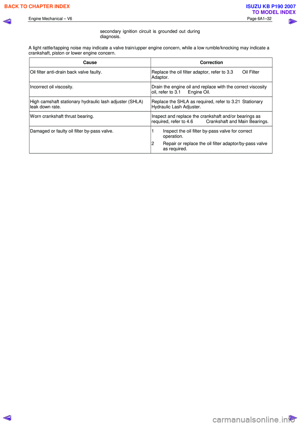
A light rattle/tapping noise may indicate a valve train/upper engine concern, while a low rumble/knocking may indicate a
crankshaft, piston or lower engine concern.
Cause Correction
Oil filter anti-drain back valve faulty. Replace the oil filter adaptor, refer to 3.3 Oil Filter
Adaptor.
Incorrect oil viscosity. Drain the engine oil and replace with the correct viscosity
oil, refer to 3.1 Engine Oil.
High camshaft stationary hydraulic lash adjuster (SHLA)
leak down rate. Replace the SHLA as required, refer to 3.21 Stationary
Hydraulic Lash Adjuster.
W orn crankshaft thrust bearing. Inspect and replace the crankshaft and/or bearings as
required, refer to 4.6 Crankshaft and Main Bearings.
Damaged or faulty oil filter by-pass valve. 1 Inspect the oil filter by-pass valve for correct
operation.
2 Repair or replace the oil filter adaptor/by-pass valve as required.
BACK TO CHAPTER INDEX
TO MODEL INDEX
ISUZU KB P190 2007
Page 2512 of 6020
Engine Mechanical – V6 Page 6A1–33
2.9 Upper Engine Noise, Regardless of
Engine Speed
NOTE
A cold piston knock, which disappears in
approximately 1.5 minutes from start up, should
be considered acceptable. A cold engine knock
usually disappears when the specific cylinder’s
secondary ignition circuit is grounded out during
diagnosis.
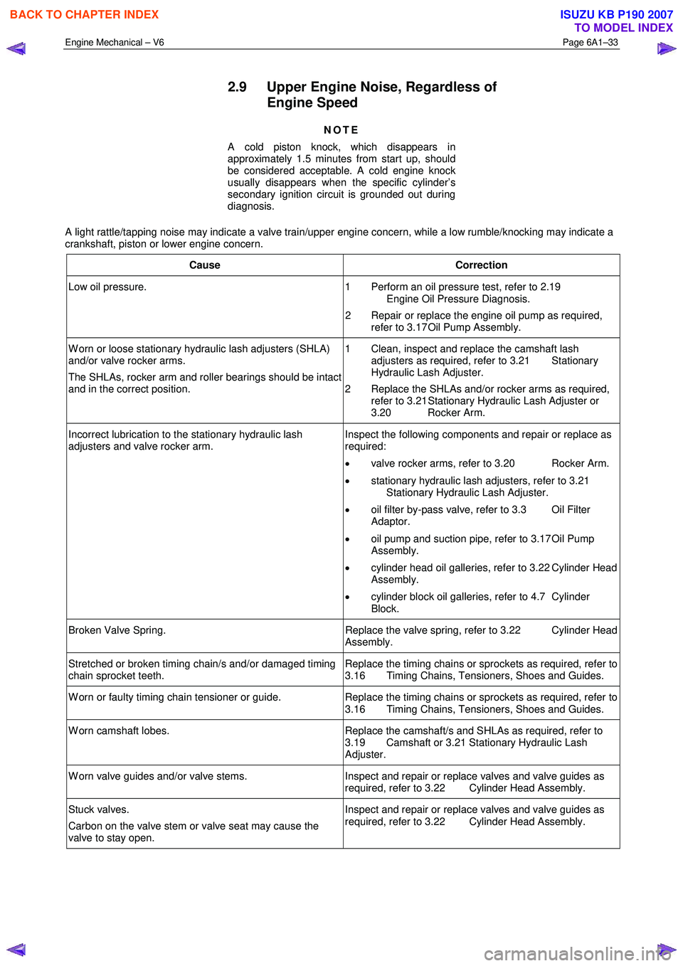
A light rattle/tapping noise may indicate a valve train/upper engine concern, while a low rumble/knocking may indicate a
crankshaft, piston or lower engine concern.
Cause Correction
Low oil pressure. 1 Perform an oil pressure test, refer to 2.19
Engine Oil Pressure Diagnosis.
2 Repair or replace the engine oil pump as required, refer to 3.17 Oil Pump Assembly.
W orn or loose stationary hydraulic lash adjusters (SHLA)
and/or valve rocker arms.
The SHLAs, rocker arm and roller bearings should be intact
and in the correct position. 1 Clean, inspect and replace the camshaft lash
adjusters as required, refer to 3.21 Stationary
Hydraulic Lash Adjuster.
2 Replace the SHLAs and/or rocker arms as required, refer to 3.21 Stationary Hydraulic Lash Adjuster or
3.20 Rocker Arm.
Incorrect lubrication to the stationary hydraulic lash
adjusters and valve rocker arm. Inspect the following components and repair or replace as
required:
• valve rocker arms, refer to 3.20 Rocker Arm.
• stationary hydraulic lash adjusters, refer to 3.21
Stationary Hydraulic Lash Adjuster.
• oil filter by-pass valve, refer to 3.3 Oil Filter
Adaptor.
• oil pump and suction pipe, refer to 3.17 Oil Pump
Assembly.
• cylinder head oil galleries, refer to 3.22 Cylinder Head
Assembly.
• cylinder block oil galleries, refer to 4.7 Cylinder
Block.
Broken Valve Spring. Replace the valve spring, refer to 3.22 Cylinder Head
Assembly.
Stretched or broken timing chain/s and/or damaged timing
chain sprocket teeth. Replace the timing chains or sprockets as required, refer to
3.16 Timing Chains, Tensioners, Shoes and Guides.
W orn or faulty timing chain tensioner or guide. Replace the timing chains or sprockets as required, refer to
3.16 Timing Chains, Tensioners, Shoes and Guides.
W orn camshaft lobes. Replace the camshaft/s and SHLAs as required, refer to
3.19 Camshaft or 3.21 Stationary Hydraulic Lash
Adjuster.
W orn valve guides and/or valve stems. Inspect and repair or replace valves and valve guides as
required, refer to 3.22 Cylinder Head Assembly.
Stuck valves.
Carbon on the valve stem or valve seat may cause the
valve to stay open. Inspect and repair or replace valves and valve guides as
required, refer to 3.22 Cylinder Head Assembly.
BACK TO CHAPTER INDEX
TO MODEL INDEX
ISUZU KB P190 2007
Page 2516 of 6020
Engine Mechanical – V6 Page 6A1–37
2.13 Coolant in Combustion Chamber
Definition
Excessive white smoke and/or coolant type odour emitted from the exhaust pipe may indicate coolant in the combustion
chamber. Low coolant levels, an inoperative engine cooling fan or a faulty thermostat may lead to an over-temperature
condition which may cause internal engine component damage. A slower than normal cranking speed may indicate
coolant entering the combustion chamber.
1 Remove the spark plugs and inspect for spark plugs saturated by coolant and coolant in the cylinder bore.
2 Inspect by performing a cylinder leakage test, refer to 2.16 Cylinder Leakage Test. During this test, excessive air bubbles in the coolant may indicate a faulty head gasket, cracked cylinder head or cracked cylinder
block.
3 Inspect by performing a cylinder compression test. Two cylinders side-by-side on the cylinder block, with low compression, may indicate a failed cylinder head gasket, refer to 2.15 Engine Compression Test.
Cause Correction
Cracked intake manifold or faulty gasket. Replace components as required, refer to 3.10
Intake Manifold Assembly – Complete.
Faulty cylinder head gasket. Replace the cylinder head gasket, refer to 3.22
Cylinder Head Assembly.
W arped cylinder head. Repair or replace the cylinder heads as required, refer to
3.22 Cylinder Head Assembly.
Cracked cylinder liner or block Repair or replace the cylinder block and components as
required, refer to 4.7 Cylinder Block.
Cylinder head or cylinder block porosity. Repair or replace the cylinder block or cylinder heads as
required, refer to 4.7 Cylinder Block or 3.22
Cylinder Head Assembly.
2.14 Coolant in Engine Oil
Definition
Foamy or discoloured oil or an engine oil overfill condition may indicate coolant entering the engine crankcase. Low
coolant levels, an inoperative engine cooling fan or a faulty thermostat may lead to an over-temperature condition which
may result in engine component damage. Contaminated engine oil and oil filters must be replaced.
1 Inspect the oil for excessive foaming or an overfill condition. Oil diluted by coolant may not correctly lubricate the crankshaft bearings, resulting in component damage, refer to 2.10 Lower Engine Noise, Regardless of Engine
Speed.
2 Perform a cylinder leakage test, refer to 2.16 Cylinder Leakage Test. During this procedure, excessive air bubbles in the engine coolant may indicate a faulty gasket or damaged component.
3 Perform a cylinder compression test. Two cylinders side-by-side on the cylinder block, with low compression, may indicate a failed cylinder head gasket, refer to 2.15 Engine Compression Test.
Cause Correction
Faulty cylinder head gasket. Replace the cylinder head gasket, refer to 3.22
Cylinder Head Assembly.
W arped cylinder head. Repair or replace the cylinder heads as required, refer to
3.22 Cylinder Head Assembly.
Cracked cylinder liner or block Repair or replace the cylinder block and components as
required, refer to 4.7 Cylinder Block.
Cylinder head, cylinder block or intake manifold porosity. Repair or replace the cylinder block, cylinder heads or intake manifold components as required, refer to 4.7
Cylinder Block, 3.22 Cylinder Head
Assembly or 3.10 Intake Manifold Assembly – Complete.
BACK TO CHAPTER INDEX
TO MODEL INDEX
ISUZU KB P190 2007
Page 2520 of 6020
Engine Mechanical – V6 Page 6A1–41
3 W ith the vehicle parked on a flat level surface, aim the black light at the suspected component/s. The dyed fluid will
appear as a yellow path leading to the oil leak source
4 Refer to Possible Causes for Engine Oil Leaks in this Section, and repair or replace components as required.
Possible Causes for Engine Oil Leaks
Common possible causes for engine oil leaks are:
• higher than recommended fluid levels,
• higher than recommended fluid pressures,
• blocked or faulty fluid filters or pressure relief valve,
• blocked or faulty engine ventilation system,
• incorrectly tightened or damaged fasteners,
• cracked or porous components,
• incorrect gaskets or sealants used,
• incorrect gaskets or sealant installation,
• damaged or worn gaskets or seals, and
• damaged or worn sealing surfaces.
BACK TO CHAPTER INDEX
TO MODEL INDEX
ISUZU KB P190 2007
Page 2521 of 6020
Engine Mechanical – V6 Page 6A1–42
2.19 Engine Oil Pressure Diagnosis
If the engine oil pressure is below the specified value, inspect the engine and components for the following:
• loose oil filter adaptor bolts,
• faulty oil filter adaptor seals,
• worn or faulty oil pump,
• loose oil pump bolts,
• loose, blocked or damaged oil pump suction pipe,
• faulty oil pump suction pipe seal,
• faulty oil pump pressure relief valve,
• faulty or incorrectly installed oil gallery plugs,
• excessive bearing clearance in one of the following:
• connecting rods big end/s,
• crankshaft main journal/s,
• camshaft/s,
• camshaft sprocket/s, and
• cracked, porous or restricted oil galleries, or broken lash adjuster/s.
2.20 Accessory Drive Belt Diagnosis
Tension Check
NOTE
An accessory drive belt that squeaks when the
engine is started or stopped is considered normal
and has no effect on drive belt durability.
1 Start the engine and switch off the air-conditioning system. Allow engine to run until normal operating temperature has been reached.
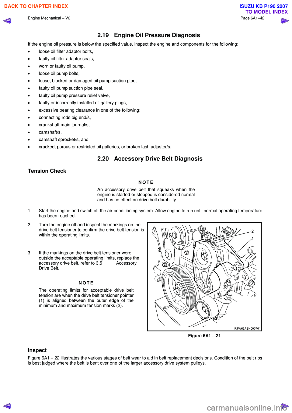
2 Turn the engine off and inspect the markings on the drive belt tensioner to confirm the drive belt tension is
within the operating limits.
3 If the markings on the drive belt tensioner were outside the acceptable operating limits, replace the
accessory drive belt, refer to 3.5 Accessory
Drive Belt.
NOTE
The operating limits for acceptable drive belt
tension are when the drive belt tensioner pointer
(1) is aligned between the outer edge of the
minimum and maximum tension marks (2).
Figure 6A1 – 21
Inspect
Figure 6A1 – 22 illustrates the various stages of belt wear to aid in belt replacement decisions. Condition of the belt ribs
is best judged where the belt is bent over one of the larger accessory drive system pulleys.
BACK TO CHAPTER INDEX
TO MODEL INDEX
ISUZU KB P190 2007
Page 2533 of 6020
Engine Mechanical – V6 Page 6A1–54
3.1 Engine Oil
The procedure outlined below is typically the same for both rear wheel drive and all wheel drive vehicles.
Check
The following procedure is applicable to both rear wheel and all wheel drive vehicles
1 Run the engine to bring it to normal operating temperature.
2 Park the vehicle on a level surface. A vehicle that is not level will affect the accuracy of the level reading.
3 Stop the engine and wait 5 to 10 minutes to allow the oil to drain back into the oil pan.
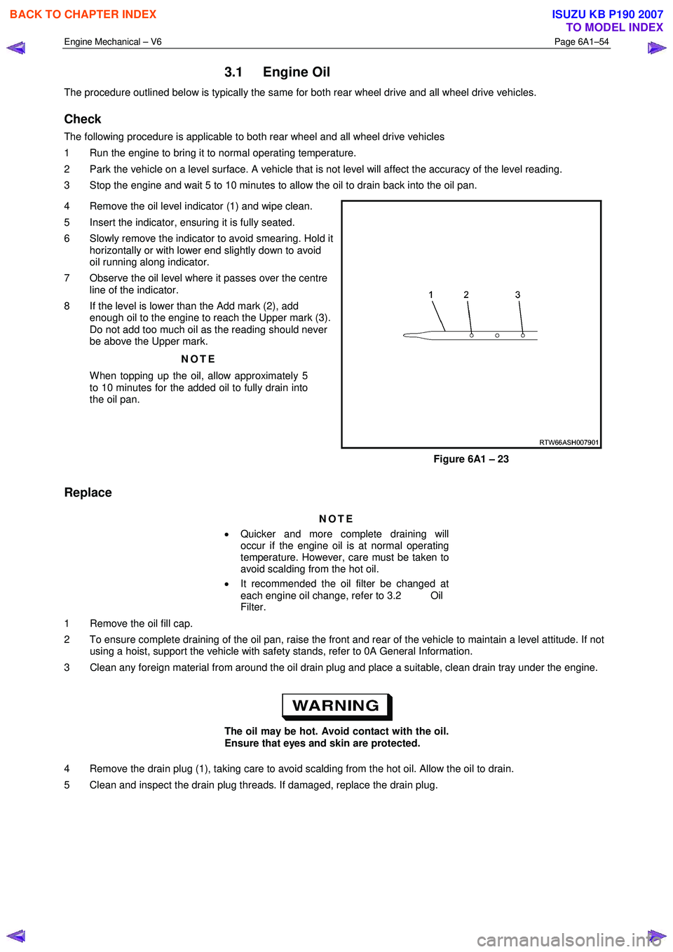
4 Remove the oil level indicator (1) and wipe clean.
5 Insert the indicator, ensuring it is fully seated.
6 Slowly remove the indicator to avoid smearing. Hold it horizontally or with lower end slightly down to avoid
oil running along indicator.
7 Observe the oil level where it passes over the centre line of the indicator.
8 If the level is lower than the Add mark (2), add enough oil to the engine to reach the Upper mark (3).
Do not add too much oil as the reading should never
be above the Upper mark.
NOTE
When topping up the oil, allow approximately 5
to 10 minutes for the added oil to fully drain into
the oil pan.
Figure 6A1 – 23
Replace
NOTE
• Quicker and more complete draining will
occur if the engine oil is at normal operating
temperature. However, care must be taken to
avoid scalding from the hot oil.
• It recommended the oil filter be changed at
each engine oil change, refer to 3.2 Oil
Filter.
1 Remove the oil fill cap.
2 To ensure complete draining of the oil pan, raise the front and rear of the vehicle to maintain a level attitude. If not using a hoist, support the vehicle with safety stands, refer to 0A General Information.
3 Clean any foreign material from around the oil drain plug and place a suitable, clean drain tray under the engine.
The oil may be hot. Avoid contact with the oil.
Ensure that eyes and skin are protected.
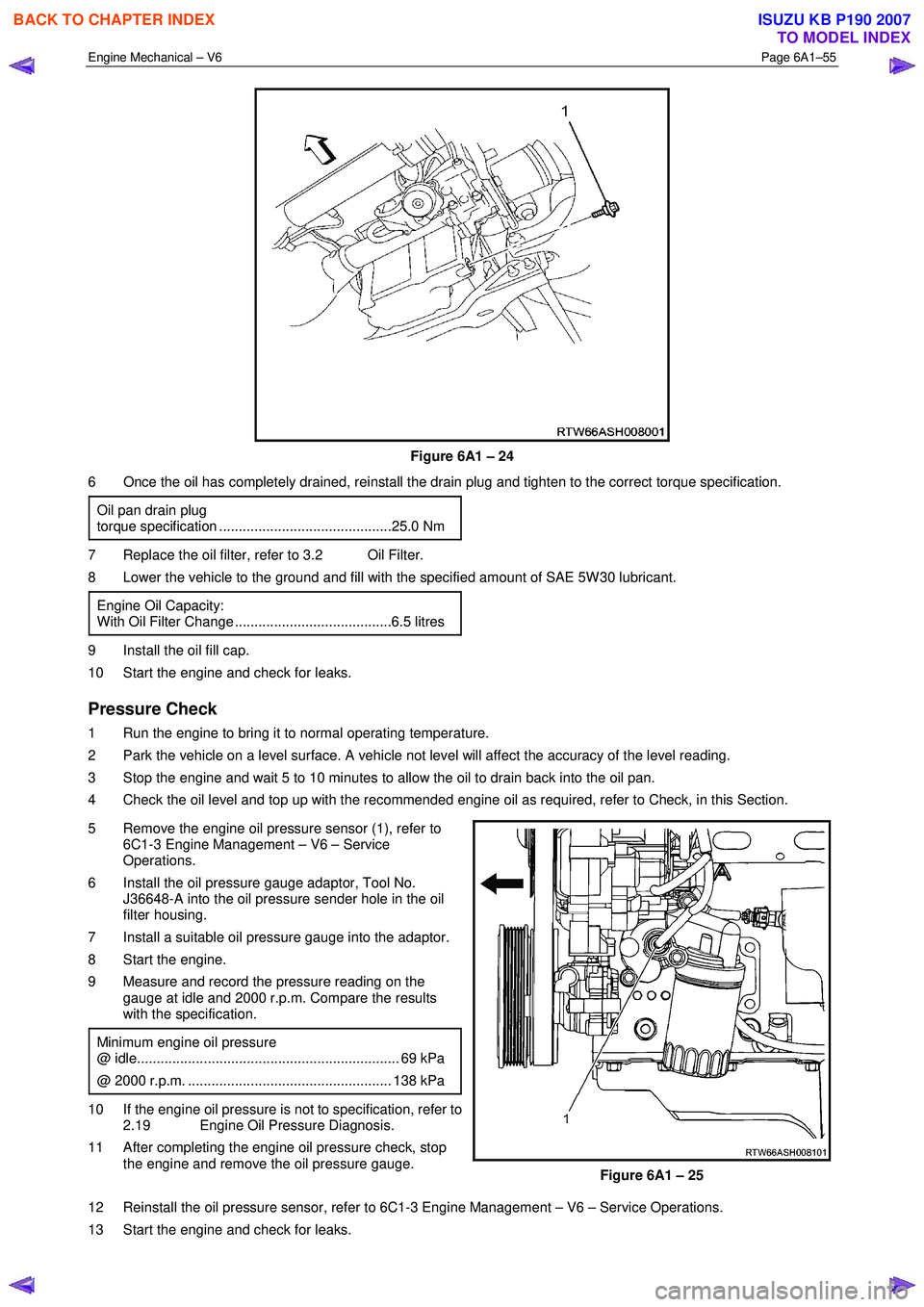
4 Remove the drain plug (1), taking care to avoid scalding from the hot oil. Allow the oil to drain.
5 Clean and inspect the drain plug threads. If damaged, replace the drain plug.
BACK TO CHAPTER INDEX
TO MODEL INDEX
ISUZU KB P190 2007
Page 2534 of 6020
Engine Mechanical – V6 Page 6A1–55
Figure 6A1 – 24
6 Once the oil has completely drained, reinstall the drain plug and tighten to the correct torque specification.
Oil pan drain plug
torque specification ............................................25.0 Nm
7 Replace the oil filter, refer to 3.2 Oil Filter.
8 Lower the vehicle to the ground and fill with the specified amount of SAE 5W 30 lubricant.
Engine Oil Capacity:
With Oil Filter Change ........................................6.5 litres
9 Install the oil fill cap.
10 Start the engine and check for leaks.
Pressure Check
1 Run the engine to bring it to normal operating temperature.
2 Park the vehicle on a level surface. A vehicle not level will affect the accuracy of the level reading.
3 Stop the engine and wait 5 to 10 minutes to allow the oil to drain back into the oil pan.
4 Check the oil level and top up with the recommended engine oil as required, refer to Check, in this Section.
5 Remove the engine oil pressure sensor (1), refer to 6C1-3 Engine Management – V6 – Service
Operations.
6 Install the oil pressure gauge adaptor, Tool No. J36648-A into the oil pressure sender hole in the oil
filter housing.
7 Install a suitable oil pressure gauge into the adaptor.
8 Start the engine.
9 Measure and record the pressure reading on the gauge at idle and 2000 r.p.m. Compare the results
with the specification.
Minimum engine oil pressure
@ idle................................................................... 69 kPa
@ 2000 r.p.m. .................................................... 138 kPa
10 If the engine oil pressure is not to specification, refer to 2.19 Engine Oil Pressure Diagnosis.
11 After completing the engine oil pressure check, stop the engine and remove the oil pressure gauge.
Figure 6A1 – 25
12 Reinstall the oil pressure sensor, refer to 6C1-3 Engine Management – V6 – Service Operations.
13 Start the engine and check for leaks.
BACK TO CHAPTER INDEX
TO MODEL INDEX
ISUZU KB P190 2007
Page 2535 of 6020
Engine Mechanical – V6 Page 6A1–56
3.2 Oil Filter Cartridge
Replace
NOTE
• The oil filter cartridge should be replaced at
the correct time or distance intervals, refer to
0B Lubrication and Service.
• The oil filter cartridge should also be replaced
whenever the engine oil is suspected to have
been contaminated by foreign material.
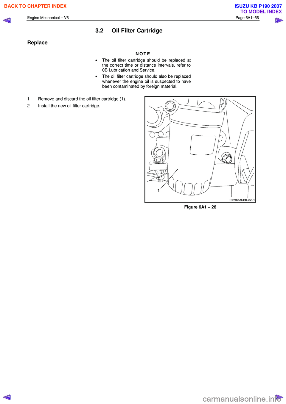
1 Remove and discard the oil filter cartridge (1).
2 Install the new oil filter cartridge.
Figure 6A1 – 26
BACK TO CHAPTER INDEX
TO MODEL INDEX
ISUZU KB P190 2007
Page 2536 of 6020
Engine Mechanical – V6 Page 6A1–57
3.3 Oil Filter Adaptor
Remove
Disconnection of the battery affects certain
vehicle electronic systems, refer to 1.1
WARNING, CAUTION and NOTES before
disconnecting the battery.
1 Disconnect the battery negative terminal.
2 Disconnect the wiring harness connector from the oil pressure sender.
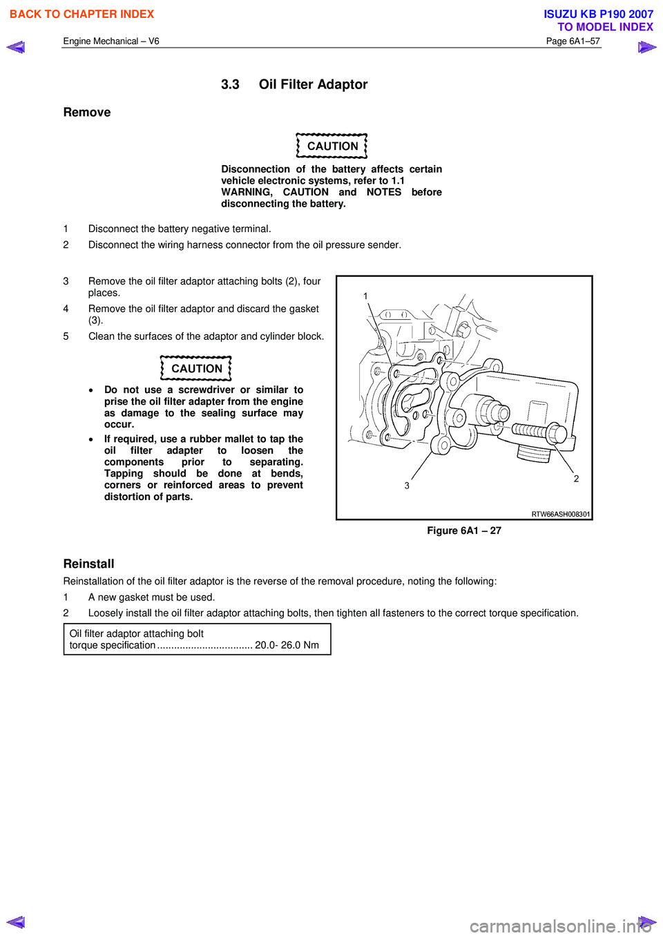
3 Remove the oil filter adaptor attaching bolts (2), four places.
4 Remove the oil filter adaptor and discard the gasket (3).
5 Clean the surfaces of the adaptor and cylinder block.
• Do not use a screwdriver or similar to
prise the oil filter adapter from the engine
as damage to the sealing surface may
occur.
• If required, use a rubber mallet to tap the
oil filter adapter to loosen the
components prior to separating.
Tapping should be done at bends,
corners or reinforced areas to prevent
distortion of parts.
Figure 6A1 – 27
Reinstall
Reinstallation of the oil filter adaptor is the reverse of the removal procedure, noting the following:
1 A new gasket must be used.
2 Loosely install the oil filter adaptor attaching bolts, then tighten all fasteners to the correct torque specification.
Oil filter adaptor attaching bolt
torque specification .................................. 20.0- 26.0 Nm
BACK TO CHAPTER INDEX
TO MODEL INDEX
ISUZU KB P190 2007