Circuit ISUZU KB P190 2007 Workshop Repair Manual
[x] Cancel search | Manufacturer: ISUZU, Model Year: 2007, Model line: KB P190, Model: ISUZU KB P190 2007Pages: 6020, PDF Size: 70.23 MB
Page 3274 of 6020

Engine Management β V6 β General Information Page 6C1-1β32
4.16 Intake Air Temperature Sensor
The intake air temperature (IAT) sensor is a thermistor,
which is a resistor that changes itβs resistance value based
on temperature.
The IAT sensor is part of the air mass sensor and is not a
serviceable item. The sensor is a negative temperature
coefficient (NTC) type, intake air temperature produces a
high sensor resistance while high engine coolant
temperature causes low sensor resistance.
Legend
A Temperature
B Resistance
The ECM provides a 5 V reference signal to the IAT and
monitors the return signal which enables it to calculate the
intake air temperature.
The ECM uses this signal to make corrections to the
operating parameters of the system based on changes in air
intake temperature.
Figure 6C1-1 β 40
4.17 Knock Sensor
The knock sensor (KS) signal is used by the ECM to provide
optimum ignition timing while minimising engine knock or
detonation.
The ECM monitors the voltage of the left-hand (Bank 2)
sensor during the 45 degrees after cylinder 2, 4, or 6 has
fired and the voltage of the right-hand (Bank 1) sensor
during the 45 degrees after cylinder 1, 3, or 5 has fired.
If knock occurs in any of the cylinders, the ignition will be
retarded by three degrees for that particular cylinder. If the
knocking then stops, the ignition will be restored to what it
was before in steps of 0.75 degrees.
Should knocking continue in the same cylinder despite of
the ignition being retarded, the ECM will retard the ignition
an additional step of three degrees, and so on, up to a
maximum of 12.75 degrees. The ignition will also be
retarded at high ambient temperatures to counteract
knocking tendencies provoked by high intake air
temperatures.
Should either Bank 1 or Bank 2 sensor fail to work, or
should an open circuit occur, the ignition timing will then be
set at a default strategy that will retard the ignition much
more than normal.
Figure 6C1-1 β 41
BACK TO CHAPTER INDEX
TO MODEL INDEX
ISUZU KB P190 2007
Page 3277 of 6020
Engine Management β V6 β General Information Page 6C1-1β35
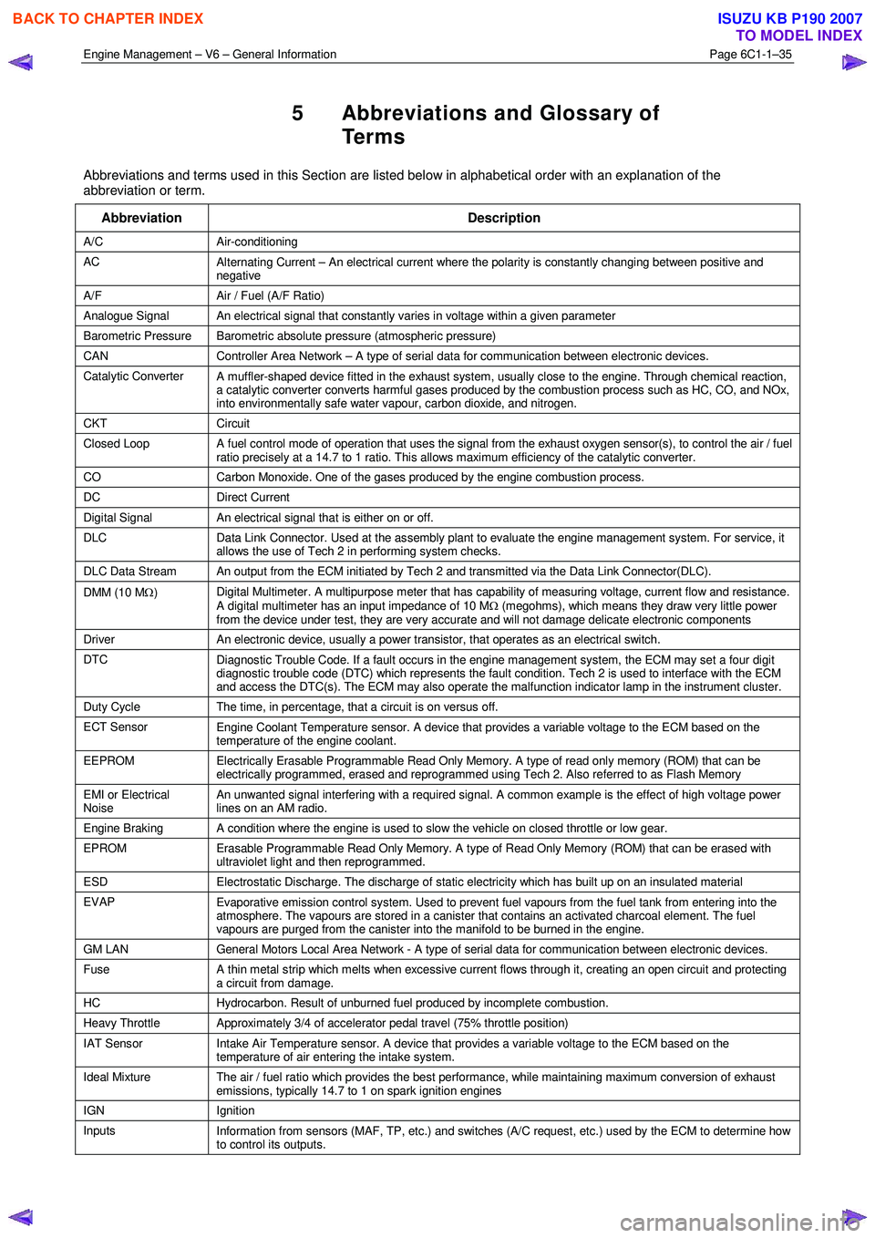
5 Abbreviations and Glossary of
Te r m s
Abbreviations and terms used in this Section are listed below in alphabetical order with an explanation of the
abbreviation or term.
Abbreviation Description
A/C Air-conditioning
AC Alternating Current β An electrical current where the polarity is constantly changing between positive and
negative
A/F Air / Fuel (A/F Ratio)
Analogue Signal An electrical signal that constantly varies in voltage within a given parameter
Barometric Pressure Barometric absolute pressure (atmospheric pressure)
CAN Controller Area Network β A type of serial data for communication between electronic devices.
Catalytic Converter
A muffler-shaped device fitted in the exhaust system, usually close to the engine. Through chemical reaction,
a catalytic converter converts harmful gases produced by the combustion process such as HC, CO, and NOx,
into environmentally safe water vapour, carbon dioxide, and nitrogen.
CKT Circuit
Closed Loop A fuel control mode of operation that uses the signal from the exhaust oxygen sensor(s), to control the air / fuel
ratio precisely at a 14.7 to 1 ratio. This allows maximum efficiency of the catalytic converter.
CO Carbon Monoxide. One of the gases produced by the engine combustion process.
DC Direct Current
Digital Signal An electrical signal that is either on or off.
DLC
Data Link Connector. Used at the assembly plant to evaluate the engine management system. For service, it
allows the use of Tech 2 in performing system checks.
DLC Data Stream An output from the ECM initiated by Tech 2 and transmitted via the Data Link Connector(DLC).
DMM (10 M β¦) Digital Multimeter. A multipurpose meter that has capability of measuring voltage, current flow and resistance.
A digital multimeter has an input impedance of 10 M β¦ (megohms), which means they draw very little power
from the device under test, they are very accurate and will not damage delicate electronic components
Driver An electronic device, usually a power transistor, that operates as an electrical switch.
DTC
Diagnostic Trouble Code. If a fault occurs in the engine management system, the ECM may set a four digit
diagnostic trouble code (DTC) which represents the fault condition. Tech 2 is used to interface with the ECM
and access the DTC(s). The ECM may also operate the malfunction indicator lamp in the instrument cluster.
Duty Cycle The time, in percentage, that a circuit is on versus off.
ECT Sensor
Engine Coolant Temperature sensor. A device that provides a variable voltage to the ECM based on the
temperature of the engine coolant.
EEPROM Electrically Erasable Programmable Read Only Memory. A type of read only memory (ROM) that can be
electrically programmed, erased and reprogrammed using Tech 2. Also referred to as Flash Memory
EMI or Electrical
Noise An unwanted signal interfering with a required signal. A common example is the effect of high voltage power
lines on an AM radio.
Engine Braking A condition where the engine is used to slow the vehicle on closed throttle or low gear.
EPROM Erasable Programmable Read Only Memory. A type of Read Only Memory (ROM) that can be erased with
ultraviolet light and then reprogrammed.
ESD Electrostatic Discharge. The discharge of static electricity which has built up on an insulated material
EVAP
Evaporative emission control system. Used to prevent fuel vapours from the fuel tank from entering into the
atmosphere. The vapours are stored in a canister that contains an activated charcoal element. The fuel
vapours are purged from the canister into the manifold to be burned in the engine.
GM LAN General Motors Local Area Network - A type of serial data for communication between electronic devices.
Fuse
A thin metal strip which melts when excessive current flows through it, creating an open circuit and protecting
a circuit from damage.
HC Hydrocarbon. Result of unburned fuel produced by incomplete combustion.
Heavy Throttle Approximately 3/4 of accelerator pedal travel (75% throttle position)
IAT Sensor
Intake Air Temperature sensor. A device that provides a variable voltage to the ECM based on the
temperature of air entering the intake system.
Ideal Mixture The air / fuel ratio which provides the best performance, while maintaining maximum conversion of exhaust
emissions, typically 14.7 to 1 on spark ignition engines
IGN Ignition
Inputs Information from sensors (MAF, TP, etc.) and switches (A/C request, etc.) used by the ECM to determine how
to control its outputs.
BACK TO CHAPTER INDEX
TO MODEL INDEX
ISUZU KB P190 2007
Page 3278 of 6020
Engine Management β V6 β General Information Page 6C1-1β36
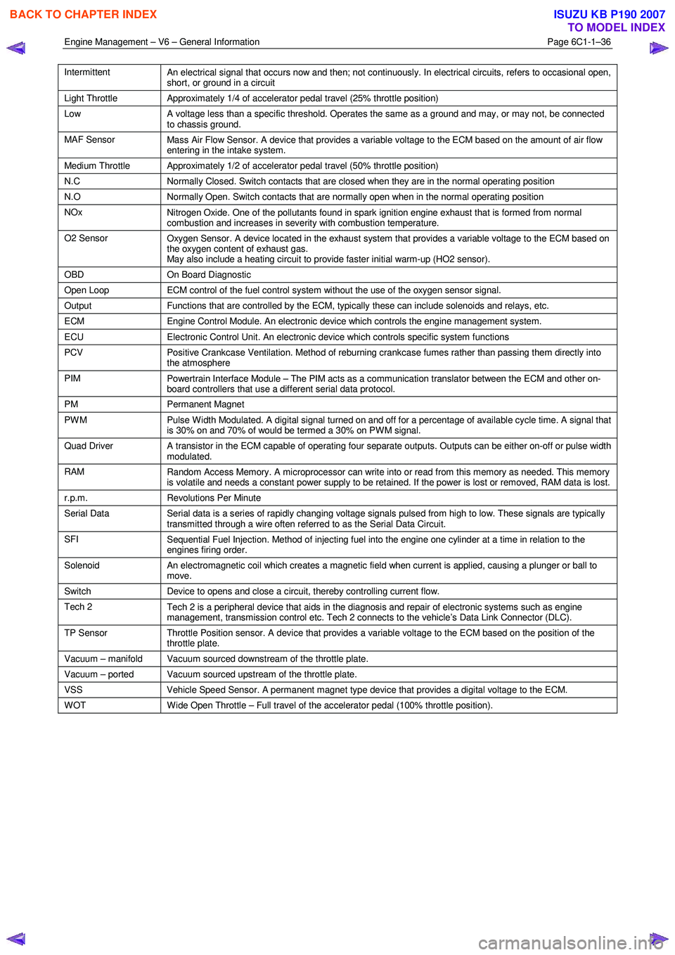
Intermittent
An electrical signal that occurs now and then; not continuously. In electrical circuits, refers to occasional open,
short, or ground in a circuit
Light Throttle Approximately 1/4 of accelerator pedal travel (25% throttle position)
Low
A voltage less than a specific threshold. Operates the same as a ground and may, or may not, be connected
to chassis ground.
MAF Sensor Mass Air Flow Sensor. A device that provides a variable voltage to the ECM based on the amount of air flow
entering in the intake system.
Medium Throttle Approximately 1/2 of accelerator pedal travel (50% throttle position)
N.C Normally Closed. Switch contacts that are closed when they are in the normal operating position
N.O Normally Open. Switch contacts that are normally open when in the normal operating position
NOx
Nitrogen Oxide. One of the pollutants found in spark ignition engine exhaust that is formed from normal
combustion and increases in severity with combustion temperature.
O2 Sensor Oxygen Sensor. A device located in the exhaust system that provides a variable voltage to the ECM based on
the oxygen content of exhaust gas.
May also include a heating circuit to provide faster initial warm-up (HO2 sensor).
OBD On Board Diagnostic
Open Loop ECM control of the fuel control system without the use of the oxygen sensor signal.
Output Functions that are controlled by the ECM, typically these can include solenoids and relays, etc.
ECM Engine Control Module. An electronic device which controls the engine management system.
ECU Electronic Control Unit. An electronic device which controls specific system functions
PCV
Positive Crankcase Ventilation. Method of reburning crankcase fumes rather than passing them directly into
the atmosphere
PIM Powertrain Interface Module β The PIM acts as a communication translator between the ECM and other on-
board controllers that use a different serial data protocol.
PM Permanent Magnet
PWM
Pulse Width Modulated. A digital signal turned on and off for a percentage of available cycle time. A signal that
is 30% on and 70% of would be termed a 30% on PWM signal.
Quad Driver A transistor in the ECM capable of operating four separate outputs. Outputs can be either on-off or pulse width
modulated.
RAM Random Access Memory. A microprocessor can write into or read from this memory as needed. This memory
is volatile and needs a constant power supply to be retained. If the power is lost or removed, RAM data is lost.
r.p.m. Revolutions Per Minute
Serial Data
Serial data is a series of rapidly changing voltage signals pulsed from high to low. These signals are typically
transmitted through a wire often referred to as the Serial Data Circuit.
SFI Sequential Fuel Injection. Method of injecting fuel into the engine one cylinder at a time in relation to the
engines firing order.
Solenoid An electromagnetic coil which creates a magnetic field when current is applied, causing a plunger or ball to
move.
Switch Device to opens and close a circuit, thereby controlling current flow.
Tech 2
Tech 2 is a peripheral device that aids in the diagnosis and repair of electronic systems such as engine
management, transmission control etc. Tech 2 connects to the vehicleβs Data Link Connector (DLC).
TP Sensor Throttle Position sensor. A device that provides a variable voltage to the ECM based on the position of the
throttle plate.
Vacuum β manifold Vacuum sourced downstream of the throttle plate.
Vacuum β ported Vacuum sourced upstream of the throttle plate.
VSS Vehicle Speed Sensor. A permanent magnet type device that provides a digital voltage to the ECM.
WOT Wide Open Throttle β Full travel of the accelerator pedal (100% throttle position).
BACK TO CHAPTER INDEX
TO MODEL INDEX
ISUZU KB P190 2007
Page 3279 of 6020
Engine Management β V6 β Diagnostics Page 6C1-2β1
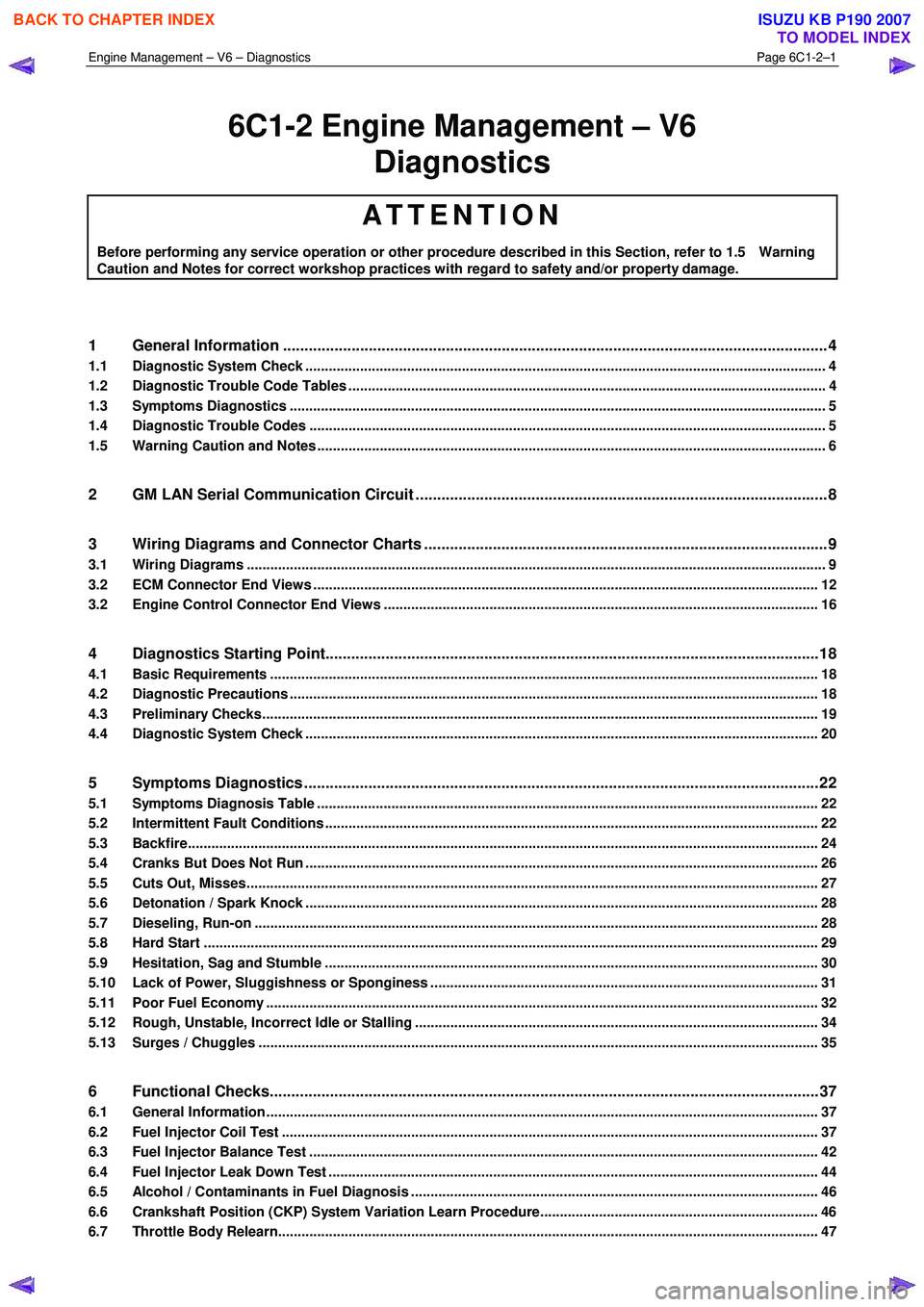
6C1-2 Engine Management β V6
Diagnostics
ATTENTION
Before performing any service operation or other procedure described in this Section, refer to 1.5 Warning
Caution and Notes for correct workshop practices with regard to safety and/or property damage.
1 General Information ............................................................................................................ ...................4
1.1 Diagnostic System Check ..................................................................................................................................... 4
1.2 Diagnostic Trouble Code Tables ................................................................................................. ......................... 4
1.3 Symptoms Diagnostics ......................................................................................................................................... 5
1.4 Diagnostic Trouble Codes .................................................................................................................................... 5
1.5 Warning Caution and Notes .................................................................................................................................. 6
2 GM LAN Serial Communication Circuit ............................................................................................ ....8
3 Wiring Diagrams and Connector Charts ........................................................................................... ...9
3.1 Wiring Diagrams .................................................................................................................................................... 9
3.2 ECM Connector End Views ................................................................................................................................. 12
3.2 Engine Control Connector End Views ............................................................................................. .................. 16
4 Diagnostics Starting Point...................................................................................................................18
4.1 Basic Requirements ............................................................................................................................................ 18
4.2 Diagnostic Precautions ......................................................................................................... .............................. 18
4.3 Preliminary Checks.............................................................................................................................................. 19
4.4 Diagnostic System Check ........................................................................................................ ........................... 20
5 Symptoms Diagnostics ........................................................................................................................22
5.1 Symptoms Diagnosis Table ....................................................................................................... ......................... 22
5.2 Intermittent Fault Conditions .............................................................................................................................. 22
5.3 Backfire................................................................................................................................................................. 24
5.4 Cranks But Does Not Run ........................................................................................................ ........................... 26
5.5 Cuts Out, Misses.................................................................................................................................................. 27
5.6 Detonation / Spark Knock ....................................................................................................... ............................ 28
5.7 Dieseling, Run-on ................................................................................................................................................ 28
5.8 Hard Start ............................................................................................................................................................. 29
5.9 Hesitation, Sag and Stumble .................................................................................................... .......................... 30
5.10 Lack of Power, Sluggishness or Sponginess ...................................................................................... ............. 31
5.11 Poor Fuel Economy ............................................................................................................................................. 32
5.12 Rough, Unstable, Incorrect Idle or Stalling .................................................................................... ................... 34
5.13 Surges / Chuggles ............................................................................................................................................... 35
6 Functional Checks................................................................................................................................37
6.1 General Information ............................................................................................................ ................................. 37
6.2 Fuel Injector Coil Test ......................................................................................................................................... 37
6.3 Fuel Injector Balance Test ..................................................................................................... ............................. 42
6.4 Fuel Injector Leak Down Test ................................................................................................... .......................... 44
6.5 Alcohol / Contaminants in Fuel Diagnosis ....................................................................................... ................. 46
6.6 Crankshaft Position (CKP) System Variation Learn Procedure..................................................................... .. 46
6.7 Throttle Body Relearn.......................................................................................................................................... 47
BACK TO CHAPTER INDEX
TO MODEL INDEX
ISUZU KB P190 2007
Page 3282 of 6020
Engine Management β V6 β Diagnostics Page 6C1-2β4
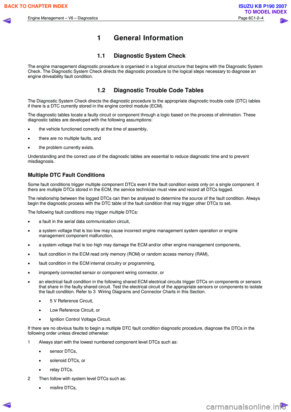
1 General Information
1.1 Diagnostic System Check
The engine management diagnostic procedure is organised in a logical structure that begins with the Diagnostic System
Check. The Diagnostic System Check directs the diagnostic procedure to the logical steps necessary to diagnose an
engine driveability fault condition.
1.2 Diagnostic Trouble Code Tables
The Diagnostic System Check directs the diagnostic procedure to the appropriate diagnostic trouble code (DTC) tables
if there is a DTC currently stored in the engine control module (ECM).
The diagnostic tables locate a faulty circuit or component through a logic based on the process of elimination. These
diagnostic tables are developed with the following assumptions:
β’ the vehicle functioned correctly at the time of assembly,
β’ there are no multiple faults, and
β’ the problem currently exists.
Understanding and the correct use of the diagnostic tables are essential to reduce diagnostic time and to prevent
misdiagnosis.
Multiple DTC Fault Conditions
Some fault conditions trigger multiple component DTCs even if the fault condition exists only on a single component. If
there are multiple DTCs stored in the ECM, the service technician must view and record all DTCs logged.
The relationship between the logged DTCs can then be analysed to determine the source of the fault condition. Always
begin the diagnostic process with the DTC table of the fault condition that may trigger other DTCs to set.
The following fault conditions may trigger multiple DTCs:
β’ a fault in the serial data communication circuit,
β’ a system voltage that is too low may cause incorrect engine management system operation or engine
management component malfunction,
β’ a system voltage that is too high may damage the ECM and/or other engine management components,
β’ fault condition in the ECM read only memory (ROM) or random access memory (RAM),
β’ fault condition in the ECM internal circuitry or programming,
β’ improperly connected sensor or component wiring connector, or
β’ an electrical fault condition in the following shared ECM electrical circuits trigger DTCs on components or sensors
that share in the faulty shared circuit. Test the electrical circuit of the appropriate sensors or components to isolate
the fault condition. Refer to 3 W iring Diagrams and Connector Charts in this Section.
β’ 5 V Reference Circuit,
β’ Low Reference Circuit, or
β’ Ignition Control Voltage Circuit.
If there are no obvious faults to begin a multiple DTC fault condition diagnostic procedure, diagnose the DTCs in the
following order unless directed otherwise:
1 Always start with the lowest numbered component level DTCs such as:
β’ sensor DTCs,
β’ solenoid DTCs, or
β’ relay DTCs.
2 Then follow with system level DTCs such as:
β’ misfire DTCs,
BACK TO CHAPTER INDEX
TO MODEL INDEX
ISUZU KB P190 2007
Page 3286 of 6020

Engine Management β V6 β Diagnostics Page 6C1-2β8
2 GM LAN Serial Communication
Circuit
Figure 6C1-2 β 1
BACK TO CHAPTER INDEX
TO MODEL INDEX
ISUZU KB P190 2007
Page 3290 of 6020

Engine Management β V6 β Diagnostics Page 6C1-2β12
3.2 ECM Connector End Views
Engine Control Module Connector E-60
Figure 6C1-2 β 5
Terminal / Pin Wire Colour Circuit
Description Function
E-60β1 BR KNK_RET2
Low Reference β Knock Sensor Bank 2
E-60β2 LG IN_PMP_2 B2S1 HO2S Input Pump Current (Bank 2 Sensor 1)
E-60β3 O IN_PMP_1 B1S1 HO2S Input Pump Current (Bank 1 Sensor 1)
E-60β4 O CMSFH_1 CMP Sensor Signal β Intake Bank 1
E-60β5 GR 5VDC2 5 Volt Reference β 6
E-60β6 Not Used
E-60β7 BR/R 5VGD2 Low Reference β Ground 2
E-60β8 V TPS_2 TP Sensor 2 Signal
E-60β9 G/W EST4 EST 4 Control
E-60β10 W ENG_SPD CKP Sensor High
E-60β11 Not Used
E-60β12 Not Used
E-60β13 Not Used
E-60β14 Not Used
E-60β15 BR ETC_POS TAC Motor Control (Positive)
E-60β16 V/W O2_HTR_1 B1S1 HO2S Heater Low Reference (Bank 1 Sensor 1)
E-60β17 GR KNK_RET1 Low Reference β Knock Sensor Bank 1
E-60β18 BR/W O2_RTN_2 B2S1 HO2S Low Signal (Bank 2 Sensor 1)
E-60β19 V HI_SIG_1 B1S1 HO2S High Signal (Bank 1 Sensor 1)
E-60β20 Not Used
E-60β21 GR CHRG_2 Generator Field Duty Cycle Signal (βFβ Terminal)
E-60β22 Not Used
E-60β23 Y COL_TMP ECT Sensor Signal
E-60β24 Not Used
E-60β25 L/W EST6 EST 6 Control
E-60β26 O/W EST2 EST 2 Control
BACK TO CHAPTER INDEX
TO MODEL INDEX
ISUZU KB P190 2007
Page 3292 of 6020
Engine Management β V6 β Diagnostics Page 6C1-2β14
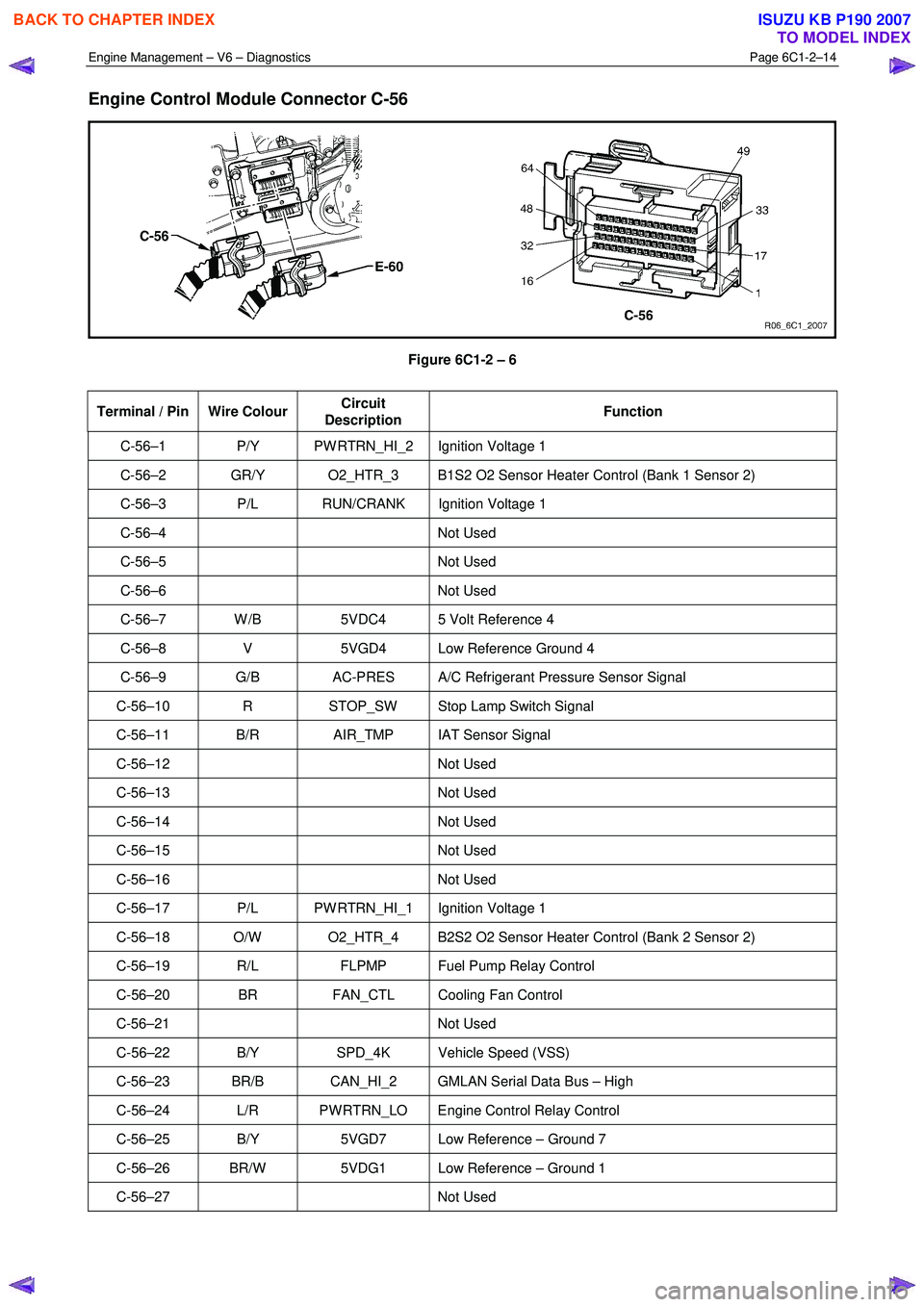
Engine Control Module Connector C-56
Figure 6C1-2 β 6
Terminal / Pin Wire Colour Circuit
Description Function
C-56β1 P/Y PW RTRN_HI_2 Ignition Voltage 1
C-56β2 GR/Y O2_HTR_3 B1S2 O2 Sensor Heater Control (Bank 1 Sensor 2)
C-56β3 P/L RUN/CRANK Ignition Voltage 1
C-56β4 Not
Used
C-56β5 Not Used
C-56β6 Not Used
C-56β7 W /B 5VDC4 5 Volt Reference 4
C-56β8 V 5VGD4 Low Reference Ground 4
C-56β9 G/B AC-PRES A/C Refrigerant Pressure Sensor Signal
C-56β10 R STOP_SW Stop Lamp Switch Signal
C-56β11 B/R AIR_TMP IAT Sensor Signal
C-56β12 Not Used
C-56β13 Not Used
C-56β14 Not Used
C-56β15 Not Used
C-56β16 Not Used
C-56β17 P/L PW RTRN_HI_1 Ignition Voltage 1
C-56β18 O/W O2_HTR_4 B2S2 O2 Sensor Heater Control (Bank 2 Sensor 2)
C-56β19 R/L FLPMP Fuel Pump Relay Control
C-56β20 BR FAN_CTL Cooling Fan Control
C-56β21 Not Used
C-56β22 B/Y SPD_4K Vehicle Speed (VSS)
C-56β23 BR/B CAN_HI_2 GMLAN Serial Data Bus β High
C-56β24 L/R PW RTRN_LO Engine Control Relay Control
C-56β25 B/Y 5VGD7 Low Reference β Ground 7
C-56β26 BR/W 5VDG1 Low Reference β Ground 1
C-56β27 Not Used
BACK TO CHAPTER INDEX
TO MODEL INDEX
ISUZU KB P190 2007
Page 3296 of 6020

Engine Management β V6 β Diagnostics Page 6C1-2β18
4 Diagnostics Starting Point
4.1 Basic Requirements
Basic Knowledge Required
A lack of basic understanding regarding
electronics, electrical wiring circuits and use
of electrical circuit testing tools when
performing an engine management system
diagnostic procedure could result in incorrect
diagnostic results or damage to engine
management system components.
Understanding of the following is required to perform the diagnostic procedures detailed in this Section. Refer to 8A
Electrical - Body and Chassis and to Basic Tools Required.
β’ Basic electronics,
β’ Electrical wiring circuits,
β’ Electrical circuits testing, and
β’ Correct use of the basic engine management system diagnostic tools.
In addition, understanding of the engine management system is essential to prevent misdiagnosis and component
damage. Refer to 6C1-1 Engine Management β V6 β General Information.
Basic Tools Required
Use of incorrect electrical circuit diagnostic
tools when performing the Engine
Management diagnostic procedures could
result in incorrect diagnostic results or
damage to engine management system
components.
The following electrical circuit testing tools are required to perform the diagnostic procedures detailed in this Section.
β’ Tech 2,
β’ Test lamp, refer to 8A Electrical - Body and Chassis, and
β’ Digital multimeter with 10 M β¦ impedance, refer to 8A Electrical - Body and Chassis.
4.2 Diagnostic Precautions
The following precautions must be observed when performing the powertrain diagnostic procedure, otherwise incorrect
diagnostic results or damage to engine management system components will occur:
β’ Disconnection of the battery affects certain vehicle electronic systems. Refer to 6D1-3 Battery β V6 before
disconnecting the battery.
β’ Disconnect the battery negative lead when performing the following procedures:
β Disconnecting the ECM connectors, or
β Charging the battery.
β’ Disconnect the battery terminal lead and the ECM connectors before attempting any electric arc welding on the
vehicle.
BACK TO CHAPTER INDEX
TO MODEL INDEX
ISUZU KB P190 2007
Page 3297 of 6020
Engine Management β V6 β Diagnostics Page 6C1-2β19
β’ Do not start the engine if the battery terminal is not properly secured to the battery.
β’ Do not disconnect or reconnect the following while the ignition is switched on or when the engine is running:
β Any engine management system component electrical wiring connector, or
β Battery terminal leads.
β’ Ensure the correct procedure for disconnecting and connecting engine management system electrical wiring
connectors is always followed. For information on the correct procedure for disconnecting and connecting specific
wiring connectors, refer to 6C1-3 Engine Management β V6 β Service Operations.
β’ Ensure that all wiring harness connectors are fitted correctly.
β’ W hen steam or pressure cleaning engines, do not direct the cleaning nozzle at engine management system
components.
β’ Do not clear any DTCs unless instructed.
β’ The fault must be present when using the diagnostic trouble code (DTC) diagnostic tables. Otherwise,
misdiagnosis or replacement of good parts may occur.
β’ Do not touch the ECM connector pins or soldered components on the ECM circuit board to prevent ECM
Electrostatic Discharge damage. Refer to 8A Electrical - Body and Chassis for information on Electrostatic
Discharge.
β’ Use only the test equipment specified in the diagnostic tables as other test equipment may give incorrect results or
damage good components.
β’ The ECM is designed to withstand normal current draw associated with vehicle operations. However, the following
fault conditions or incorrect test procedure may overload the ECM internal circuit and damage the ECM:
β A short to voltage fault condition in any of the ECM low reference circuits may cause internal ECM and / or
sensor damage. Therefore, any short to voltage fault condition in the ECM low reference circuits must be
rectified before replacing a faulty component.
β A short to ground fault condition in any of the ECM 5 V reference circuits may cause internal ECM and / or
sensor damage. Therefore, any short to ground fault condition in the ECM 5 V reference circuits must be
rectified before replacing a faulty component.
β W hen using a test lamp to test an electrical circuit, do not use any of the ECM low reference circuits or 5 V
reference circuits as a reference point. Otherwise, excessive current draw from the test lamp may damage
the ECM.
β’ Disregard DTCs that set while performing the following diagnostic Steps:
β Using Tech 2 actuator tests, or
β Disconnecting an engine management system sensor connector then switching on the ignition.
β’ After completing the required diagnostics and service operations, road test the vehicle to ensure correct engine
management system operation.
4.3 Preliminary Checks
The preliminary checks are a set of visual and physical checks or inspections that may quickly identify engine
management system fault condition.
β’ Refer to the appropriate Service Techlines for relevant information regarding the fault condition.
β’ Ensure the battery is fully charged.
β’ Inspect the battery connections for corrosion or a loose terminal.
β’ Ensure that all engine management system related fuses are serviceable.
β’ Inspect for incorrect aftermarket theft deterrent devices, lights or mobile phone installation.
β’ Ensure there is no speaker magnet positioned too close to any electronic module that contains relays.
β’ Inspect the engine wiring harness for proper connections, pinches or cuts.
β’ Ensure that all engine management related electrical wiring connectors are fitted correctly.
β’ Inspect the ECM ground connections for corrosion, loose terminal or incorrect position.
BACK TO CHAPTER INDEX
TO MODEL INDEX
ISUZU KB P190 2007