sensor ISUZU KB P190 2007 Workshop Repair Manual
[x] Cancel search | Manufacturer: ISUZU, Model Year: 2007, Model line: KB P190, Model: ISUZU KB P190 2007Pages: 6020, PDF Size: 70.23 MB
Page 3292 of 6020
Engine Management – V6 – Diagnostics Page 6C1-2–14
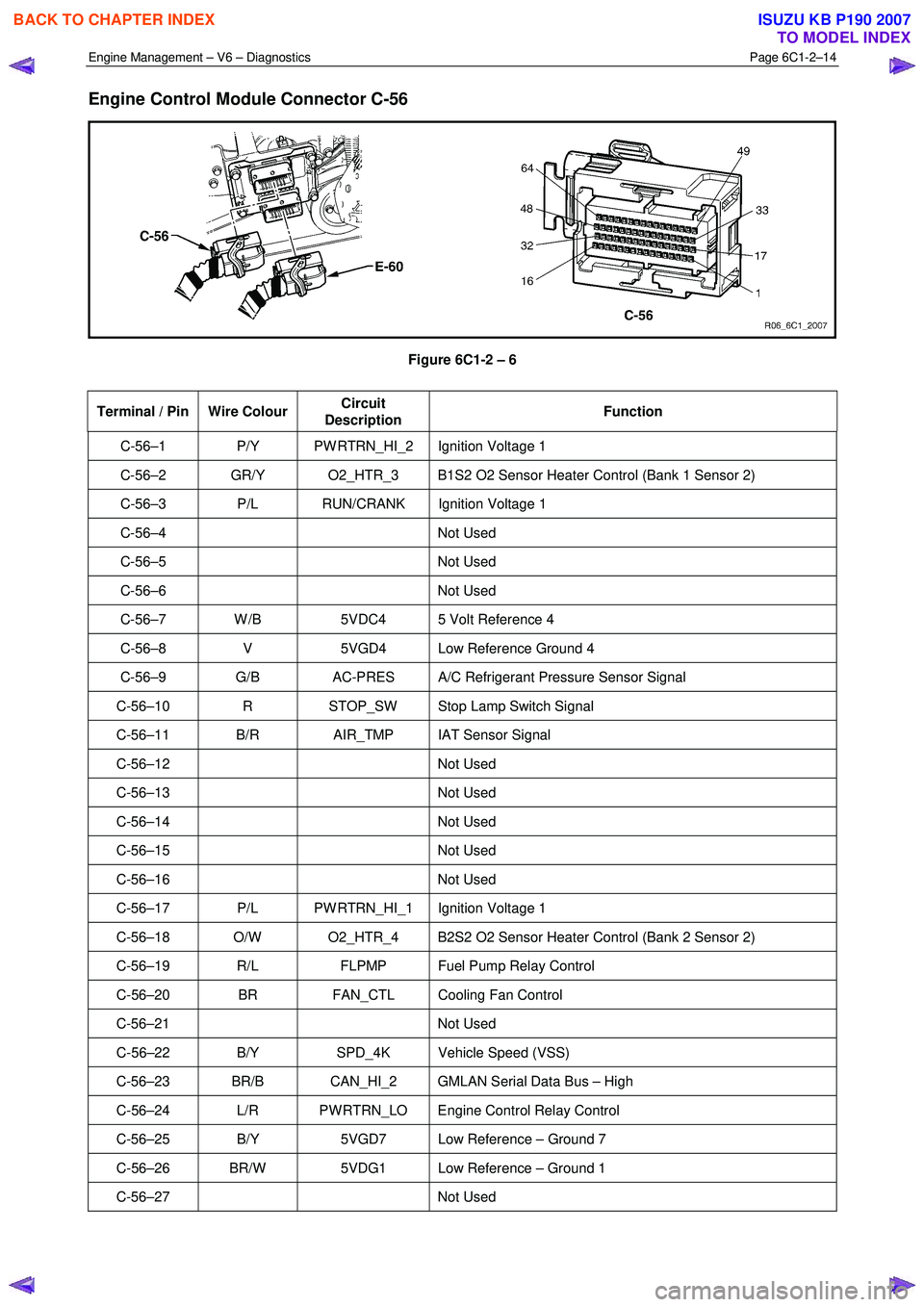
Engine Control Module Connector C-56
Figure 6C1-2 – 6
Terminal / Pin Wire Colour Circuit
Description Function
C-56–1 P/Y PW RTRN_HI_2 Ignition Voltage 1
C-56–2 GR/Y O2_HTR_3 B1S2 O2 Sensor Heater Control (Bank 1 Sensor 2)
C-56–3 P/L RUN/CRANK Ignition Voltage 1
C-56–4 Not
Used
C-56–5 Not Used
C-56–6 Not Used
C-56–7 W /B 5VDC4 5 Volt Reference 4
C-56–8 V 5VGD4 Low Reference Ground 4
C-56–9 G/B AC-PRES A/C Refrigerant Pressure Sensor Signal
C-56–10 R STOP_SW Stop Lamp Switch Signal
C-56–11 B/R AIR_TMP IAT Sensor Signal
C-56–12 Not Used
C-56–13 Not Used
C-56–14 Not Used
C-56–15 Not Used
C-56–16 Not Used
C-56–17 P/L PW RTRN_HI_1 Ignition Voltage 1
C-56–18 O/W O2_HTR_4 B2S2 O2 Sensor Heater Control (Bank 2 Sensor 2)
C-56–19 R/L FLPMP Fuel Pump Relay Control
C-56–20 BR FAN_CTL Cooling Fan Control
C-56–21 Not Used
C-56–22 B/Y SPD_4K Vehicle Speed (VSS)
C-56–23 BR/B CAN_HI_2 GMLAN Serial Data Bus – High
C-56–24 L/R PW RTRN_LO Engine Control Relay Control
C-56–25 B/Y 5VGD7 Low Reference – Ground 7
C-56–26 BR/W 5VDG1 Low Reference – Ground 1
C-56–27 Not Used
BACK TO CHAPTER INDEX
TO MODEL INDEX
ISUZU KB P190 2007
Page 3293 of 6020
Engine Management – V6 – Diagnostics Page 6C1-2–15
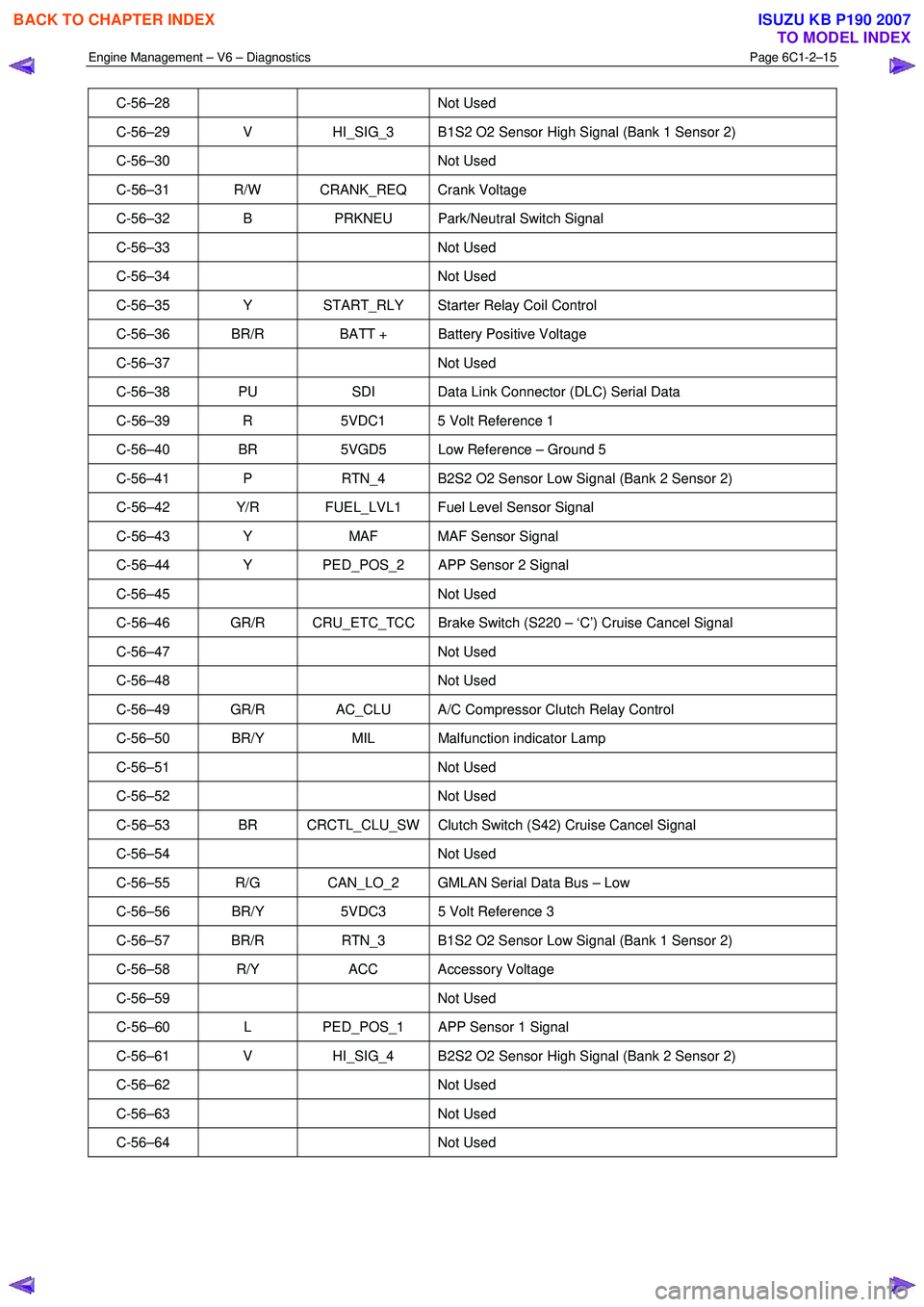
C-56–28 Not Used
C-56–29 V HI_SIG_3 B1S2 O2 Sensor High Signal (Bank 1 Sensor 2)
C-56–30 Not Used
C-56–31 R/W CRANK_REQ Crank Voltage
C-56–32 B PRKNEU Park/Neutral Switch Signal
C-56–33 Not Used
C-56–34 Not Used
C-56–35 Y START_RLY Starter Relay Coil Control
C-56–36 BR/R BATT + Battery Positive Voltage
C-56–37 Not Used
C-56–38 PU SDI Data Link Connector (DLC) Serial Data
C-56–39 R 5VDC1 5 Volt Reference 1
C-56–40 BR 5VGD5 Low Reference – Ground 5
C-56–41 P RTN_4 B2S2 O2 Sensor Low Signal (Bank 2 Sensor 2)
C-56–42 Y/R FUEL_LVL1 Fuel Level Sensor Signal
C-56–43 Y MAF MAF Sensor Signal
C-56–44 Y PED_POS_2 APP Sensor 2 Signal
C-56–45 Not Used
C-56–46 GR/R CRU_ETC_TCC Brake Switch (S220 – ‘C’) Cruise Cancel Signal
C-56–47 Not Used
C-56–48 Not Used
C-56–49 GR/R AC_CLU A/C Compressor Clutch Relay Control
C-56–50 BR/Y MIL Malfunction indicator Lamp
C-56–51 Not Used
C-56–52 Not Used
C-56–53 BR CRCTL_CLU_SW Clutch Switch (S42) Cruise Cancel Signal
C-56–54 Not Used
C-56–55 R/G CAN_LO_2 GMLAN Serial Data Bus – Low
C-56–56 BR/Y 5VDC3 5 Volt Reference 3
C-56–57 BR/R RTN_3 B1S2 O2 Sensor Low Signal (Bank 1 Sensor 2)
C-56–58 R/Y ACC Accessory Voltage
C-56–59 Not Used
C-56–60 L PED_POS_1 APP Sensor 1 Signal
C-56–61 V HI_SIG_4 B2S2 O2 Sensor High Signal (Bank 2 Sensor 2)
C-56–62 Not Used
C-56–63 Not Used
C-56–64 Not Used
BACK TO CHAPTER INDEX
TO MODEL INDEX
ISUZU KB P190 2007
Page 3297 of 6020
Engine Management – V6 – Diagnostics Page 6C1-2–19
• Do not start the engine if the battery terminal is not properly secured to the battery.
• Do not disconnect or reconnect the following while the ignition is switched on or when the engine is running:
− Any engine management system component electrical wiring connector, or
− Battery terminal leads.
• Ensure the correct procedure for disconnecting and connecting engine management system electrical wiring
connectors is always followed. For information on the correct procedure for disconnecting and connecting specific
wiring connectors, refer to 6C1-3 Engine Management – V6 – Service Operations.
• Ensure that all wiring harness connectors are fitted correctly.
• W hen steam or pressure cleaning engines, do not direct the cleaning nozzle at engine management system
components.
• Do not clear any DTCs unless instructed.
• The fault must be present when using the diagnostic trouble code (DTC) diagnostic tables. Otherwise,
misdiagnosis or replacement of good parts may occur.
• Do not touch the ECM connector pins or soldered components on the ECM circuit board to prevent ECM
Electrostatic Discharge damage. Refer to 8A Electrical - Body and Chassis for information on Electrostatic
Discharge.
• Use only the test equipment specified in the diagnostic tables as other test equipment may give incorrect results or
damage good components.
• The ECM is designed to withstand normal current draw associated with vehicle operations. However, the following
fault conditions or incorrect test procedure may overload the ECM internal circuit and damage the ECM:
− A short to voltage fault condition in any of the ECM low reference circuits may cause internal ECM and / or
sensor damage. Therefore, any short to voltage fault condition in the ECM low reference circuits must be
rectified before replacing a faulty component.
− A short to ground fault condition in any of the ECM 5 V reference circuits may cause internal ECM and / or
sensor damage. Therefore, any short to ground fault condition in the ECM 5 V reference circuits must be
rectified before replacing a faulty component.
− W hen using a test lamp to test an electrical circuit, do not use any of the ECM low reference circuits or 5 V
reference circuits as a reference point. Otherwise, excessive current draw from the test lamp may damage
the ECM.
• Disregard DTCs that set while performing the following diagnostic Steps:
− Using Tech 2 actuator tests, or
− Disconnecting an engine management system sensor connector then switching on the ignition.
• After completing the required diagnostics and service operations, road test the vehicle to ensure correct engine
management system operation.
4.3 Preliminary Checks
The preliminary checks are a set of visual and physical checks or inspections that may quickly identify engine
management system fault condition.
• Refer to the appropriate Service Techlines for relevant information regarding the fault condition.
• Ensure the battery is fully charged.
• Inspect the battery connections for corrosion or a loose terminal.
• Ensure that all engine management system related fuses are serviceable.
• Inspect for incorrect aftermarket theft deterrent devices, lights or mobile phone installation.
• Ensure there is no speaker magnet positioned too close to any electronic module that contains relays.
• Inspect the engine wiring harness for proper connections, pinches or cuts.
• Ensure that all engine management related electrical wiring connectors are fitted correctly.
• Inspect the ECM ground connections for corrosion, loose terminal or incorrect position.
BACK TO CHAPTER INDEX
TO MODEL INDEX
ISUZU KB P190 2007
Page 3298 of 6020
Engine Management – V6 – Diagnostics Page 6C1-2–20
• Ensure the resistance between the ECM housing and the battery negative cable is less than 0.5 Ω.
• Check the ECM bracket fasteners for correct torque value.
• Check all engine management related components for correct installation.
• Inspect the vacuum hoses for splits, kinks, oil contamination and proper connections, refer to the vehicle emission
control information label. Check the hoses thoroughly for any type of leak or restriction.
• Inspect the air intake ducts for being collapsed, split or for having damaged areas.
• Inspect for air leaks at the throttle body mounting area, mass air flow (MAF) sensor, intake manifold and intake
manifold sealing surfaces.
• Check for wiring harness routing that may be positioned too close to a high voltage or high current device such as
the following:
− Secondary ignition components, and
− Motors and generators.
NOTE
High voltage or high current devices may induce
electrical noise on a circuit, which can interfere
with normal circuit operation.
4.4 Diagnostic System Check
Description
The engine management diagnostic procedure is organised in a logical structure that begins with the Diagnostic System
Check. The Diagnostic System Check directs the diagnostic procedure to the logical steps necessary to diagnose an
engine driveability fault condition.
Test Description
The following numbers refer to the step numbers in the diagnostic table:
6 Tests the integrity of the GM LAN serial data communication circuit. A PIM DTC sets if the PIM detects a fault condition in the communication circuit. A fault condition on the serial data communication circuit may trigger
multiple DTCs on other sensors and components.
Step Action Yes No
1 Have you read the basic requirements?
Go to Step 2 Refer to
4.1 Basic
Requirements
2 Have you read the diagnostic precautions?
Go to Step 3 Refer to
4.2 Diagnostic Precautions
3 Have you performed the preliminary checks?
Go to Step 4 Refer to
4.3 Preliminary Checks
4 Using Tech 2, attempt to communicate with the PIM.
Does the PIM fail to communicate? Refer to 6E1
Powertrain Interface Module – V6 Go to Step 5
5 Does DTC B3902, C0550, U2100, U2105, U2106, P0633, or P1611
also set in the PIM? Refer to 6E1
Powertrain Interface Module – V6 Go to Step 6
6 Using Tech 2, view and record DTCs set at the ECM and TCM.
Does Tech 2 display any DTC? Go to Step 7 Refer to
5.1 Symptoms
Diagnosis Table
BACK TO CHAPTER INDEX
TO MODEL INDEX
ISUZU KB P190 2007
Page 3302 of 6020
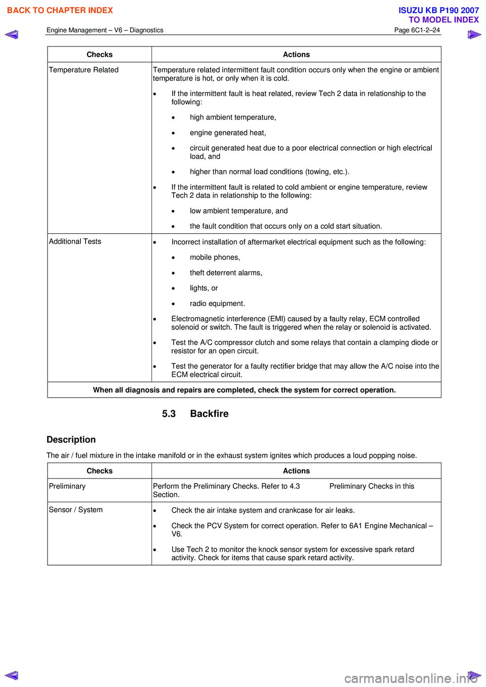
Engine Management – V6 – Diagnostics Page 6C1-2–24
Checks Actions
Temperature Related Temperature related intermittent fault condition occurs only when the engine or ambient
temperature is hot, or only when it is cold.
• If the intermittent fault is heat related, review Tech 2 data in relationship to the
following:
• high ambient temperature,
• engine generated heat,
• circuit generated heat due to a poor electrical connection or high electrical
load, and
• higher than normal load conditions (towing, etc.).
• If the intermittent fault is related to cold ambient or engine temperature, review
Tech 2 data in relationship to the following:
• low ambient temperature, and
• the fault condition that occurs only on a cold start situation.
Additional Tests
• Incorrect installation of aftermarket electrical equipment such as the following:
• mobile phones,
• theft deterrent alarms,
• lights, or
• radio equipment.
• Electromagnetic interference (EMI) caused by a faulty relay, ECM controlled
solenoid or switch. The fault is triggered when the relay or solenoid is activated.
• Test the A/C compressor clutch and some relays that contain a clamping diode or
resistor for an open circuit.
• Test the generator for a faulty rectifier bridge that may allow the A/C noise into the
ECM electrical circuit.
When all diagnosis and repairs are completed, check the system for correct operation.
5.3 Backfire
Description
The air / fuel mixture in the intake manifold or in the exhaust system ignites which produces a loud popping noise.
Checks Actions
Preliminary Perform the Preliminary Checks. Refer to 4.3 Preliminary Checks in this
Section.
Sensor / System • Check the air intake system and crankcase for air leaks.
• Check the PCV System for correct operation. Refer to 6A1 Engine Mechanical –
V6.
• Use Tech 2 to monitor the knock sensor system for excessive spark retard
activity. Check for items that cause spark retard activity.
BACK TO CHAPTER INDEX
TO MODEL INDEX
ISUZU KB P190 2007
Page 3303 of 6020
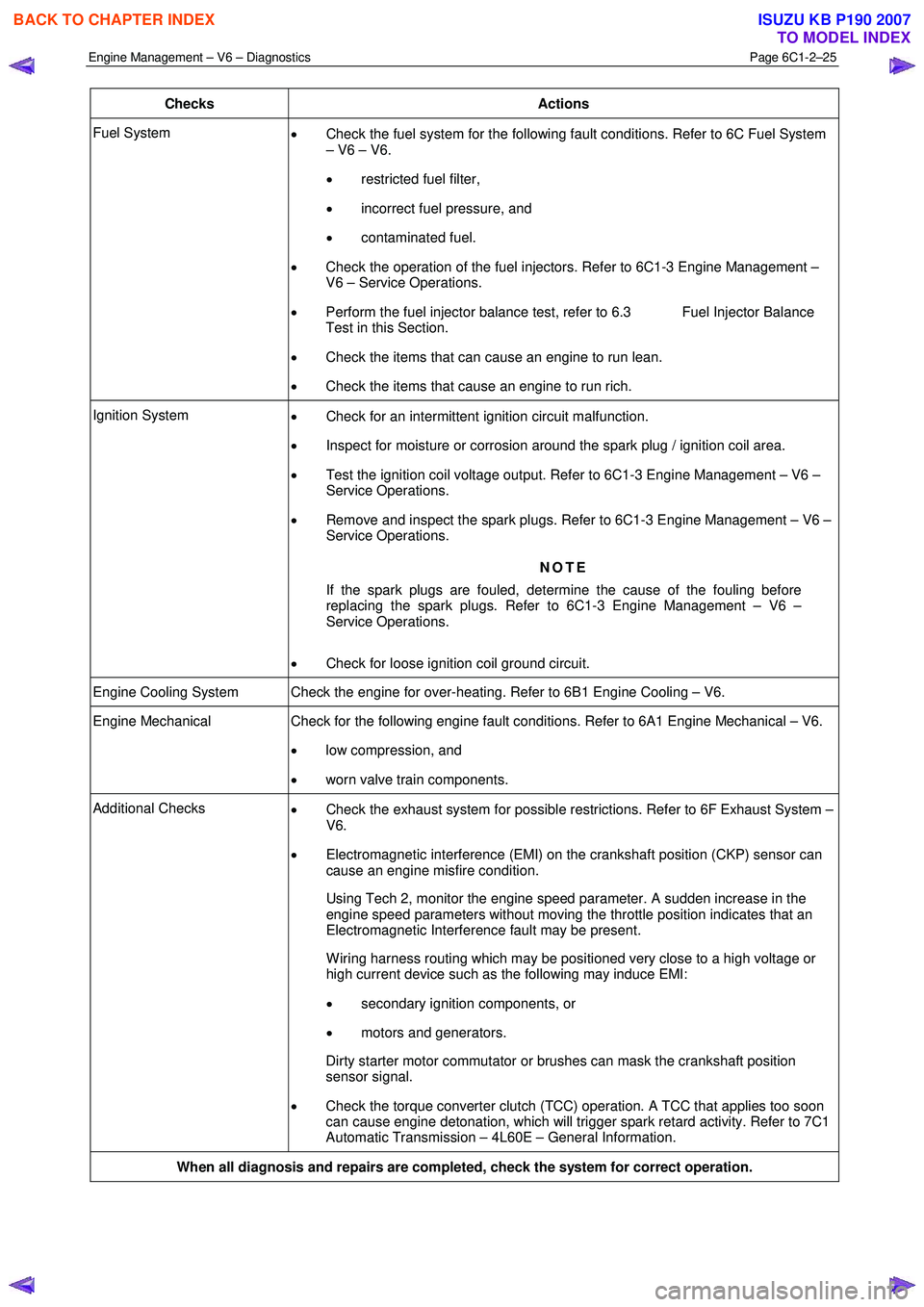
Engine Management – V6 – Diagnostics Page 6C1-2–25
Checks Actions
Fuel System
• Check the fuel system for the following fault conditions. Refer to 6C Fuel System
– V6 – V6.
• restricted fuel filter,
• incorrect fuel pressure, and
• contaminated fuel.
• Check the operation of the fuel injectors. Refer to 6C1-3 Engine Management –
V6 – Service Operations.
• Perform the fuel injector balance test, refer to 6.3 Fuel Injector Balance
Test in this Section.
• Check the items that can cause an engine to run lean.
• Check the items that cause an engine to run rich.
Ignition System
• Check for an intermittent ignition circuit malfunction.
• Inspect for moisture or corrosion around the spark plug / ignition coil area.
• Test the ignition coil voltage output. Refer to 6C1-3 Engine Management – V6 –
Service Operations.
• Remove and inspect the spark plugs. Refer to 6C1-3 Engine Management – V6 –
Service Operations.
NOTE
If the spark plugs are fouled, determine the cause of the fouling before
replacing the spark plugs. Refer to 6C1-3 Engine Management – V6 –
Service Operations.
• Check for loose ignition coil ground circuit.
Engine Cooling System Check the engine for over-heating. Refer to 6B1 Engine Cooling – V6.
Engine Mechanical Check for the following engine fault conditions. Refer to 6A1 Engine Mechanical – V6.
• low compression, and
• worn valve train components.
Additional Checks
• Check the exhaust system for possible restrictions. Refer to 6F Exhaust System –
V6.
• Electromagnetic interference (EMI) on the crankshaft position (CKP) sensor can
cause an engine misfire condition.
Using Tech 2, monitor the engine speed parameter. A sudden increase in the engine speed parameters without moving the throttle position indicates that an
Electromagnetic Interference fault may be present.
W iring harness routing which may be positioned very close to a high voltage or high current device such as the following may induce EMI:
• secondary ignition components, or
• motors and generators.
Dirty starter motor commutator or brushes can mask the crankshaft position sensor signal.
• Check the torque converter clutch (TCC) operation. A TCC that applies too soon
can cause engine detonation, which will trigger spark retard activity. Refer to 7C1
Automatic Transmission – 4L60E – General Information.
When all diagnosis and repairs are completed, check the system for correct operation.
BACK TO CHAPTER INDEX
TO MODEL INDEX
ISUZU KB P190 2007
Page 3304 of 6020
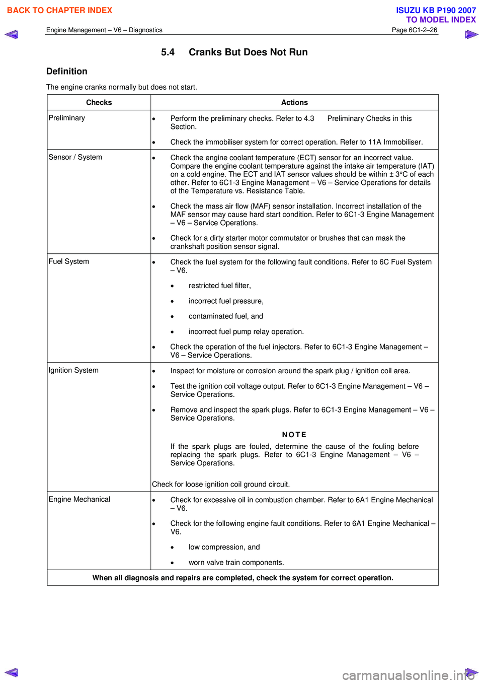
Engine Management – V6 – Diagnostics Page 6C1-2–26
5.4 Cranks But Does Not Run
Definition
The engine cranks normally but does not start.
Checks Actions
Preliminary • Perform the preliminary checks. Refer to 4.3 Preliminary Checks in this
Section.
• Check the immobiliser system for correct operation. Refer to 11A Immobiliser.
Sensor / System
• Check the engine coolant temperature (ECT) sensor for an incorrect value.
Compare the engine coolant temperature against the intake air temperature (IAT)
on a cold engine. The ECT and IAT sensor values should be within ± 3°C of each
other. Refer to 6C1-3 Engine Management – V6 – Service Operations for details
of the Temperature vs. Resistance Table.
• Check the mass air flow (MAF) sensor installation. Incorrect installation of the
MAF sensor may cause hard start condition. Refer to 6C1-3 Engine Management
– V6 – Service Operations.
• Check for a dirty starter motor commutator or brushes that can mask the
crankshaft position sensor signal.
Fuel System • Check the fuel system for the following fault conditions. Refer to 6C Fuel System
– V6.
• restricted fuel filter,
• incorrect fuel pressure,
• contaminated fuel, and
• incorrect fuel pump relay operation.
• Check the operation of the fuel injectors. Refer to 6C1-3 Engine Management –
V6 – Service Operations.
Ignition System • Inspect for moisture or corrosion around the spark plug / ignition coil area.
• Test the ignition coil voltage output. Refer to 6C1-3 Engine Management – V6 –
Service Operations.
• Remove and inspect the spark plugs. Refer to 6C1-3 Engine Management – V6 –
Service Operations.
NOTE
If the spark plugs are fouled, determine the cause of the fouling before
replacing the spark plugs. Refer to 6C1-3 Engine Management – V6 –
Service Operations.
Check for loose ignition coil ground circuit.
Engine Mechanical • Check for excessive oil in combustion chamber. Refer to 6A1 Engine Mechanical
– V6.
• Check for the following engine fault conditions. Refer to 6A1 Engine Mechanical –
V6.
• low compression, and
• worn valve train components.
When all diagnosis and repairs are completed, check the system for correct operation.
BACK TO CHAPTER INDEX
TO MODEL INDEX
ISUZU KB P190 2007
Page 3305 of 6020
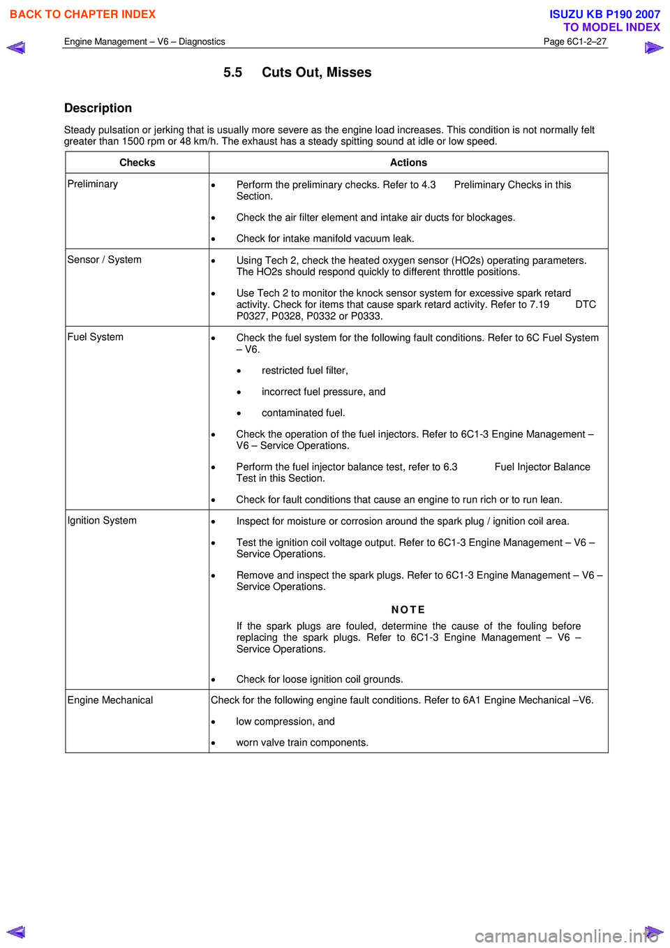
Engine Management – V6 – Diagnostics Page 6C1-2–27
5.5 Cuts Out, Misses
Description
Steady pulsation or jerking that is usually more severe as the engine load increases. This condition is not normally felt
greater than 1500 rpm or 48 km/h. The exhaust has a steady spitting sound at idle or low speed.
Checks Actions
Preliminary • Perform the preliminary checks. Refer to 4.3 Preliminary Checks in this
Section.
• Check the air filter element and intake air ducts for blockages.
• Check for intake manifold vacuum leak.
Sensor / System
• Using Tech 2, check the heated oxygen sensor (HO2s) operating parameters.
The HO2s should respond quickly to different throttle positions.
• Use Tech 2 to monitor the knock sensor system for excessive spark retard
activity. Check for items that cause spark retard activity. Refer to 7.19 DTC
P0327, P0328, P0332 or P0333.
Fuel System • Check the fuel system for the following fault conditions. Refer to 6C Fuel System
– V6.
• restricted fuel filter,
• incorrect fuel pressure, and
• contaminated fuel.
• Check the operation of the fuel injectors. Refer to 6C1-3 Engine Management –
V6 – Service Operations.
• Perform the fuel injector balance test, refer to 6.3 Fuel Injector Balance
Test in this Section.
• Check for fault conditions that cause an engine to run rich or to run lean.
Ignition System
• Inspect for moisture or corrosion around the spark plug / ignition coil area.
• Test the ignition coil voltage output. Refer to 6C1-3 Engine Management – V6 –
Service Operations.
• Remove and inspect the spark plugs. Refer to 6C1-3 Engine Management – V6 –
Service Operations.
NOTE
If the spark plugs are fouled, determine the cause of the fouling before
replacing the spark plugs. Refer to 6C1-3 Engine Management – V6 –
Service Operations.
• Check for loose ignition coil grounds.
Engine Mechanical Check for the following engine fault conditions. Refer to 6A1 Engine Mechanical –V6.
• low compression, and
• worn valve train components.
BACK TO CHAPTER INDEX
TO MODEL INDEX
ISUZU KB P190 2007
Page 3306 of 6020
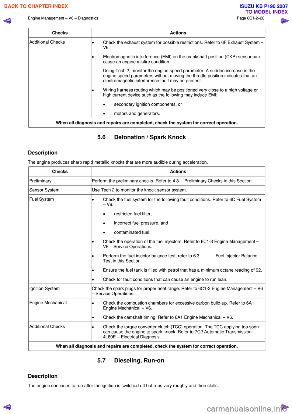
Engine Management – V6 – Diagnostics Page 6C1-2–28
Checks Actions
Additional Checks
• Check the exhaust system for possible restrictions. Refer to 6F Exhaust System –
V6.
• Electromagnetic interference (EMI) on the crankshaft position (CKP) sensor can
cause an engine misfire condition.
Using Tech 2, monitor the engine speed parameter. A sudden increase in the engine speed parameters without moving the throttle position indicates that an
electromagnetic interference fault may be present.
• W iring harness routing which may be positioned very close to a high voltage or
high current device such as the following may induce EMI:
• secondary ignition components, or
• motors and generators.
When all diagnosis and repairs are completed, check the system for correct operation.
5.6 Detonation / Spark Knock
Description
The engine produces sharp rapid metallic knocks that are more audible during acceleration.
Checks Actions
Preliminary Perform the preliminary checks. Refer to 4.3 Preliminary Checks in this Section.
Sensor System Use Tech 2 to monitor the knock sensor system.
Fuel System
• Check the fuel system for the following fault conditions. Refer to 6C Fuel System
– V6.
• restricted fuel filter,
• incorrect fuel pressure, and
• contaminated fuel.
• Check the operation of the fuel injectors. Refer to 6C1-3 Engine Management –
V6 – Service Operations.
• Perform the fuel injector balance test, refer to 6.3 Fuel Injector Balance
Test in this Section.
• Ensure the fuel tank is filled with petrol that has a minimum octane reading of 92.
• Check for fault conditions that can cause an engine to run lean.
Ignition System Check the spark plugs for proper heat range. Refer to 6C1-3 Engine Management – V6
– Service Operations.
Engine Mechanical • Check the combustion chambers for excessive carbon build-up. Refer to 6A1
Engine Mechanical – V6.
• Check the camshaft timing. Refer to 6A1 Engine Mechanical – V6.
Additional Checks
• Check the torque converter clutch (TCC) operation. The TCC applying too soon
can cause the engine to spark knock. Refer to 7C2 Automatic Transmission –
4L60E – Electrical Diagnosis.
When all diagnosis and repairs are completed, check the system for correct operation.
5.7 Dieseling, Run-on
Description
The engine continues to run after the ignition is switched off but runs very roughly and then stalls.
BACK TO CHAPTER INDEX
TO MODEL INDEX
ISUZU KB P190 2007
Page 3307 of 6020
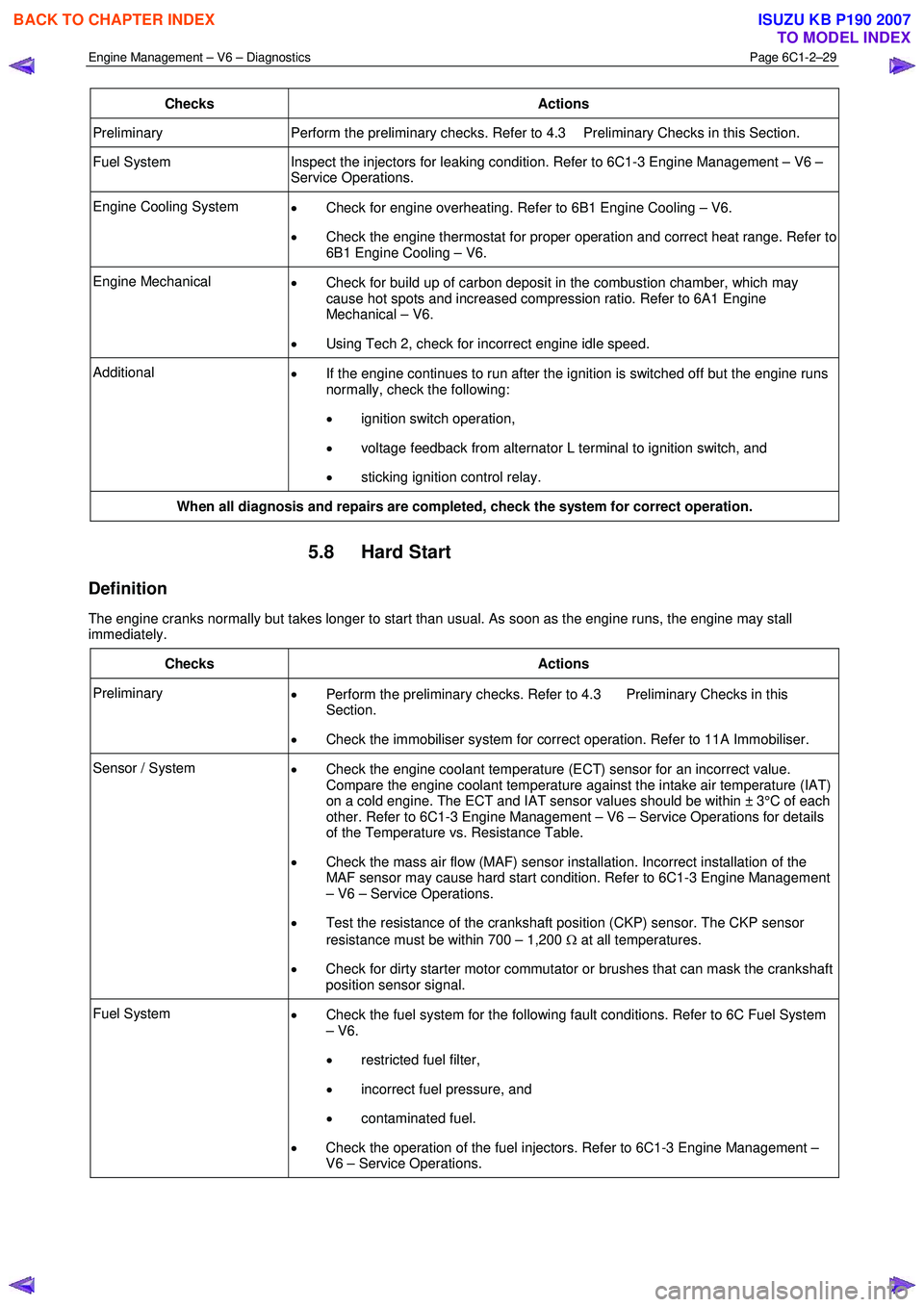
Engine Management – V6 – Diagnostics Page 6C1-2–29
Checks Actions
Preliminary Perform the preliminary checks. Refer to 4.3 Preliminary Checks in this Section.
Fuel System Inspect the injectors for leaking condition. Refer to 6C1-3 Engine Management – V6 –
Service Operations.
Engine Cooling System • Check for engine overheating. Refer to 6B1 Engine Cooling – V6.
• Check the engine thermostat for proper operation and correct heat range. Refer to
6B1 Engine Cooling – V6.
Engine Mechanical • Check for build up of carbon deposit in the combustion chamber, which may
cause hot spots and increased compression ratio. Refer to 6A1 Engine
Mechanical – V6.
• Using Tech 2, check for incorrect engine idle speed.
Additional
• If the engine continues to run after the ignition is switched off but the engine runs
normally, check the following:
• ignition switch operation,
• voltage feedback from alternator L terminal to ignition switch, and
• sticking ignition control relay.
When all diagnosis and repairs are completed, check the system for correct operation.
5.8 Hard Start
Definition
The engine cranks normally but takes longer to start than usual. As soon as the engine runs, the engine may stall
immediately.
Checks Actions
Preliminary • Perform the preliminary checks. Refer to 4.3 Preliminary Checks in this
Section.
• Check the immobiliser system for correct operation. Refer to 11A Immobiliser.
Sensor / System
• Check the engine coolant temperature (ECT) sensor for an incorrect value.
Compare the engine coolant temperature against the intake air temperature (IAT)
on a cold engine. The ECT and IAT sensor values should be within ± 3°C of each
other. Refer to 6C1-3 Engine Management – V6 – Service Operations for details
of the Temperature vs. Resistance Table.
• Check the mass air flow (MAF) sensor installation. Incorrect installation of the
MAF sensor may cause hard start condition. Refer to 6C1-3 Engine Management
– V6 – Service Operations.
• Test the resistance of the crankshaft position (CKP) sensor. The CKP sensor
resistance must be within 700 – 1,200 Ω at all temperatures.
• Check for dirty starter motor commutator or brushes that can mask the crankshaft
position sensor signal.
Fuel System • Check the fuel system for the following fault conditions. Refer to 6C Fuel System
– V6.
• restricted fuel filter,
• incorrect fuel pressure, and
• contaminated fuel.
• Check the operation of the fuel injectors. Refer to 6C1-3 Engine Management –
V6 – Service Operations.
BACK TO CHAPTER INDEX
TO MODEL INDEX
ISUZU KB P190 2007