ESP ISUZU KB P190 2007 Workshop Manual Online
[x] Cancel search | Manufacturer: ISUZU, Model Year: 2007, Model line: KB P190, Model: ISUZU KB P190 2007Pages: 6020, PDF Size: 70.23 MB
Page 2629 of 6020
Engine Mechanical – V6 Page 6A1–150
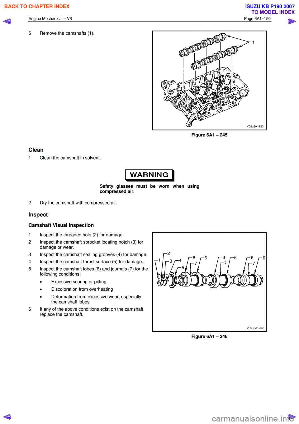
5 Remove the camshafts (1).
Figure 6A1 – 245
Clean
1 Clean the camshaft in solvent.
Safety glasses must be worn when using
compressed air.
2 Dry the camshaft with compressed air.
Inspect
Camshaft Visual Inspection
1 Inspect the threaded hole (2) for damage.
2 Inspect the camshaft sprocket locating notch (3) for damage or wear.
3 Inspect the camshaft sealing grooves (4) for damage.
4 Inspect the camshaft thrust surface (5) for damage.
5 Inspect the camshaft lobes (6) and journals (7) for the following conditions:
• Excessive scoring or pitting
• Discoloration from overheating
• Deformation from excessive wear, especially
the camshaft lobes
6 If any of the above conditions exist on the camshaft, replace the camshaft.
Figure 6A1 – 246
BACK TO CHAPTER INDEX
TO MODEL INDEX
ISUZU KB P190 2007
Page 2801 of 6020
Engine Mechanical – V6 Page 6A1–24
Page 6A1–24
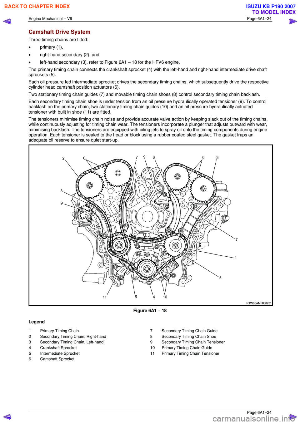
Camshaft Drive System
Three timing chains are fitted:
• primary (1),
• right-hand secondary (2), and
• left-hand secondary (3), refer to Figure 6A1 – 18 for the HFV6 engine.
The primary timing chain connects the crankshaft sprocket (4) with the left-hand and right-hand intermediate drive shaft
sprockets (5).
Each oil pressure fed intermediate sprocket drives the se condary timing chains, which subsequently drive the respective
cylinder head camshaft position actuators (6).
Two stationary timing chain guides (7) and movable timing c hain shoes (8) control secondary timing chain backlash.
Each secondary timing chain shoe is under tension from an oil pressure hydraulically operated tensioner (9). To control
backlash on the primary chain, two st ationary timing chain guides (10) and an oil pressure hydraulically actuated
tensioner with built in shoe (11) are fitted.
The tensioners minimise timing chain noise and provide accura te valve action by keeping slack out of the timing chains,
while continuously adjusting for timing chain wear. The tensioners incorporate a plunger that adjusts outward with wear,
minimising backlash. The tensioners are equipped with oiling jets to spray oil onto the timing components during engine
operation. Each tensioner is sealed to the head or block using a rubber coated steel gasket. The gasket traps an
adequate oil reserve to ens ure quiet start-up.
Figure 6A1 – 18
Legend
1 Primary Timing Chain
2 Secondary Timing Chain, Right-hand
3 Secondary Timing Chain, Left-hand
4 Crankshaft Sprocket
5 Intermediate Sprocket
6 Camshaft Sprocket 7 Secondary Timing Chain Guide
8 Secondary Timing Chain Shoe
9 Secondary Timing Chain Tensioner
10 Primary Timing Chain Guide
11 Primary Timing Chain Tensioner
BACK TO CHAPTER INDEX
TO MODEL INDEX
ISUZU KB P190 2007
Page 2965 of 6020
Engine Mechanical – V6 Page 6A1–188
Page 6A1–188
CAUTION
Ensure the tips of Tool No.
EN-46108 are fully engaged into the timing
chain and the wing nuts are tight and the
timing chain is taught.
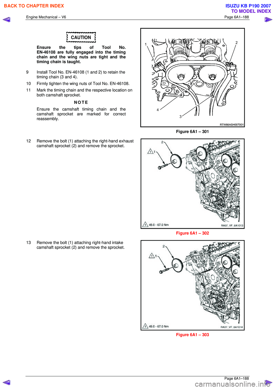
9 Install Tool No. EN-46108 (1 and 2) to retain the timing chain (3 and 4).
10 Firmly tighten the wing nuts of Tool No. EN-46108.
11 Mark the timing chain and the respective location on both camshaft sprocket.
NOTE
Ensure the camshaft timing chain and the
camshaft sprocket are marked for correct
reassembly.
Figure 6A1 – 301
12 Remove the bolt (1) attaching the right-hand exhaust camshaft sprocket (2) and remove the sprocket.
Figure 6A1 – 302
13 Remove the bolt (1) attaching right-hand intake camshaft sprocket (2) and remove the sprocket.
Figure 6A1 – 303
BACK TO CHAPTER INDEX
TO MODEL INDEX
ISUZU KB P190 2007
Page 2967 of 6020
Engine Mechanical – V6 Page 6A1–190
Page 6A1–190
NOTE
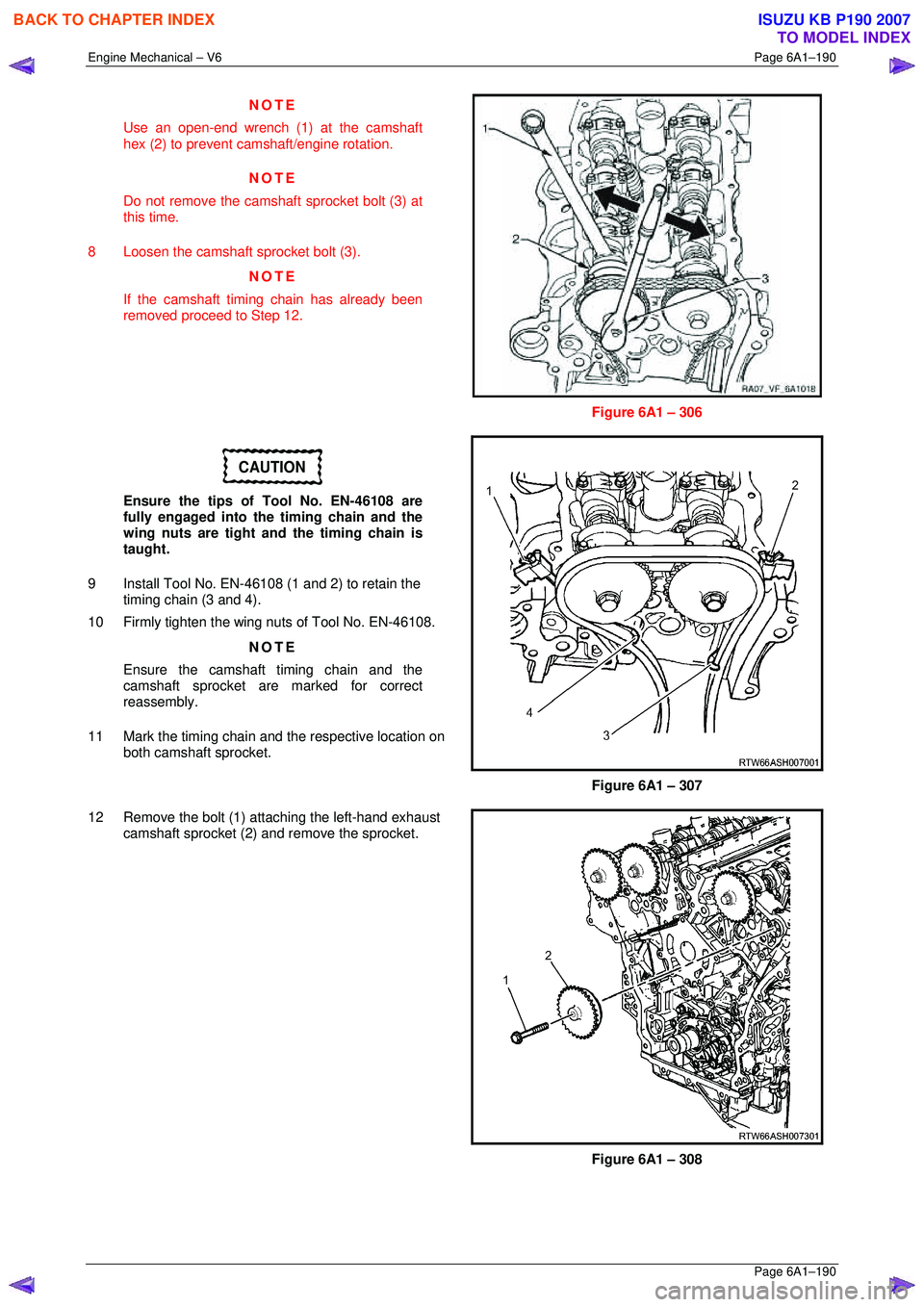
Use an open-end wrench (1) at the camshaft
hex (2) to prevent camshaft/engine rotation.
NOTE
Do not remove the cams haft sprocket bolt (3) at
this time.
8 Loosen the camshaft sprocket bolt (3). NOTE
If the camshaft timing chain has already been
removed proceed to Step 12.
Figure 6A1 – 306
CAUTION
Ensure the tips of Tool No. EN-46108 are
fully engaged into the timing chain and the
wing nuts are tight and the timing chain is
taught.
9 Install Tool No. EN-46108 (1 and 2) to retain the timing chain (3 and 4).
10 Firmly tighten the wing nuts of Tool No. EN-46108.
NOTE
Ensure the camshaft timing chain and the
camshaft sprocket are marked for correct
reassembly.
11 Mark the timing chain and the respective location on both camshaft sprocket.
Figure 6A1 – 307
12 Remove the bolt (1) attaching the left-hand exhaust camshaft sprocket (2) and remove the sprocket.
Figure 6A1 – 308
BACK TO CHAPTER INDEX
TO MODEL INDEX
ISUZU KB P190 2007
Page 2972 of 6020
Engine Mechanical – V6 Page 6A1–195
Page 6A1–195
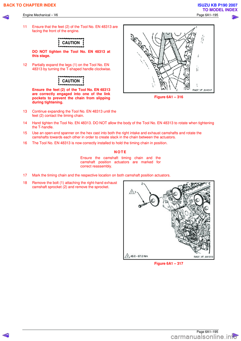
11 Ensure that the feet (2) of the Tool No. EN 48313 are
facing the front of the engine.
CAUTION
DO NOT tighten the Tool No. EN 48313 at
this stage.
12 Partially expand the legs (1) on the Tool No. EN 48313 by turning the T-shaped handle clockwise.
CAUTION
Ensure the feet (2) of the Tool No. EN 48313
are correctly engaged into one of the link
pockets to prevent the chain from slipping
during tightening.
13 Continue expanding the Tool No. EN 48313 until the feet (2) contact the timing chain.
Figure 6A1 – 316
14 Hand tighten the Tool No. EN 48313. DO NOT allow the body of the Tool No. EN 48313 to rotate when tightening
the T-handle.
15 Use an open-end spanner on the hex cast into both the right intake and exhaust camshafts and rotate the
camshafts towards each other in order to creat e slack in the chain between the actuators.
16 The Tool No. EN 48313 is now correctly inst alled to hold the timing chain in position.
NOTE
Ensure the camshaft timing chain and the
camshaft position actuators are marked for
correct reassembly.
17 Mark the timing chain and the respective location on both camshaft position actuators.
18 Remove the bolt (1) attaching the right-hand exhaust camshaft sprocket (2) and remove the sprocket.
Figure 6A1 – 317
BACK TO CHAPTER INDEX
TO MODEL INDEX
ISUZU KB P190 2007
Page 2975 of 6020
Engine Mechanical – V6 Page 6A1–198
Page 6A1–198
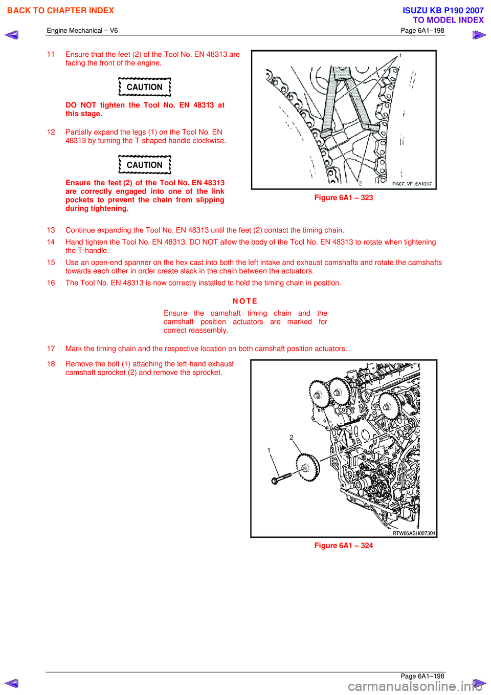
11 Ensure that the feet (2) of the Tool No. EN 48313 are
facing the front of the engine.
CAUTION
DO NOT tighten the Tool No. EN 48313 at
this stage.
12 Partially expand the legs (1) on the Tool No. EN 48313 by turning the T-shaped handle clockwise.
CAUTION
Ensure the feet (2) of the Tool No. EN 48313
are correctly engaged into one of the link
pockets to prevent the chain from slipping
during tightening.
Figure 6A1 – 323
13 Continue expanding the Tool No. EN 48313 until the feet (2) contact the timing chain.
14 Hand tighten the Tool No. EN 48313. DO NOT allow the body of the Tool No. EN 48313 to rotate when tightening
the T-handle.
15 Use an open-end spanner on the hex cast into both the left intake and exhaust camshafts and rotate the camshafts
towards each other in order create sla ck in the chain between the actuators.
16 The Tool No. EN 48313 is now correctly inst alled to hold the timing chain in position.
NOTE
Ensure the camshaft timing chain and the
camshaft position actuators are marked for
correct reassembly.
17 Mark the timing chain and the respective location on both camshaft position actuators.
18 Remove the bolt (1) attaching the left-hand exhaust camshaft sprocket (2) and remove the sprocket.
Figure 6A1 – 324
BACK TO CHAPTER INDEX
TO MODEL INDEX
ISUZU KB P190 2007
Page 2982 of 6020
Engine Mechanical – V6 Page 6A1–205
Page 6A1–205
Inspect
Camshaft Visual Inspection
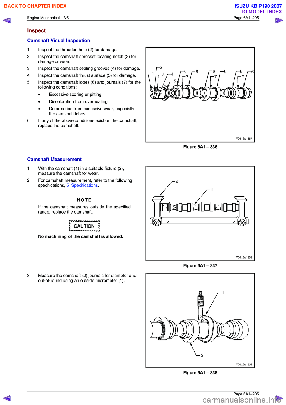
1 Inspect the threaded hole (2) for damage.
2 Inspect the camshaft spro cket locating notch (3) for
damage or wear.
3 Inspect the camshaft sealing grooves (4) for damage.
4 Inspect the camshaft thrust surface (5) for damage.
5 Inspect the camshaft lobes (6) and journals (7) for the following conditions:
• Excessive scoring or pitting
• Discoloration from overheating
• Deformation from excessive wear, especially
the camshaft lobes
6 If any of the above conditions exist on the camshaft, replace the camshaft.
Figure 6A1 – 336
Camshaft Measurement
1 With the camshaft (1) in a suitable fixture (2), measure the camshaft for wear.
2 For camshaft measurement, refer to the following specifications, 5 Specifications .
NOTE
If the camshaft measures outside the specified
range, replace the camshaft.
CAUTION
No machining of the camshaft is allowed.
Figure 6A1 – 337
3 Measure the camshaft (2) journals for diameter and out-of-round using an outsi de micrometer (1).
Figure 6A1 – 338
BACK TO CHAPTER INDEX
TO MODEL INDEX
ISUZU KB P190 2007
Page 3154 of 6020
Engine Cooling – V6 Engine Page 6B1–19
a Place a few drops of distilled water (between 21 and 29° C) onto the measuring window, then close the
plastic cover.
b Point the tester toward any light source, look into the eyepiece and check that the indicated reading is zero. If not, then re-calibrate the tester as detailed at the end of this Test Method, Calibrating the Tester.
2 Release the tip of the bulb pump from under the refractometer body. It is not necessary to remove the
complete pump from the tool.
Refer to 3.1 Service Notes in this
Section, for important safety items.
3 Carefully remove the coolant filler cap.
4 Insert the tube of the pump into the coolant, and then press the bulb to obtain a sample.
5 Bend the tube around and insert the end into the cover plate opening.
Figure 6B1 – 15
6 Press the pump bulb to deposit a few drops of coolant onto the measuring surface. Do not open the plastic cover when taking readings, as moisture evaporation will change the reading obtained.
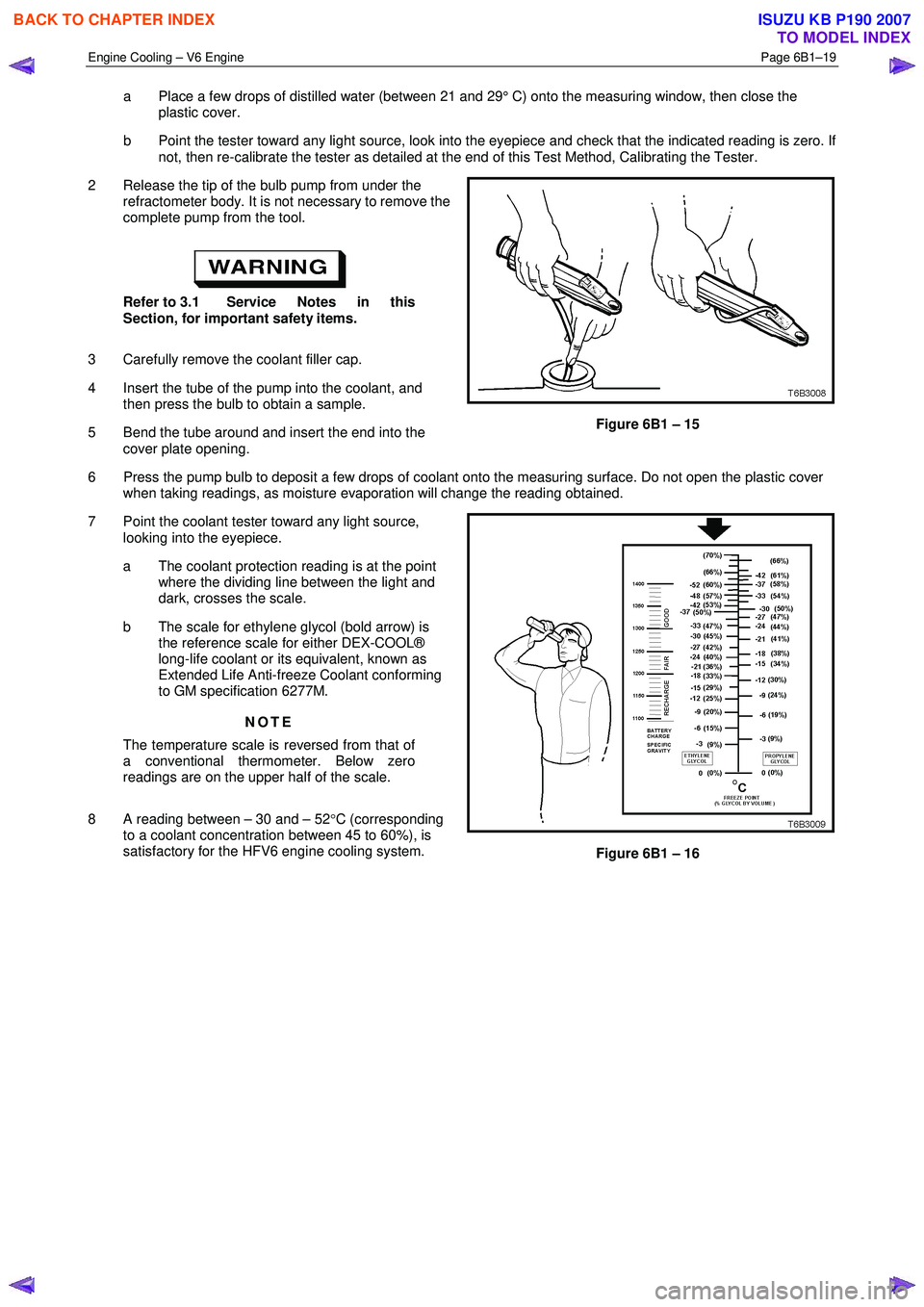
7 Point the coolant tester toward any light source, looking into the eyepiece.
a The coolant protection reading is at the point where the dividing line between the light and
dark, crosses the scale.
b The scale for ethylene glycol (bold arrow) is the reference scale for either DEX-COOL®
long-life coolant or its equivalent, known as
Extended Life Anti-freeze Coolant conforming
to GM specification 6277M.
NOTE
The temperature scale is reversed from that of
a conventional thermometer. Below zero
readings are on the upper half of the scale.
8 A reading between – 30 and – 52 °C (corresponding
to a coolant concentration between 45 to 60%), is
satisfactory for the HFV6 engine cooling system.
Figure 6B1 – 16
BACK TO CHAPTER INDEX
TO MODEL INDEX
ISUZU KB P190 2007
Page 3196 of 6020
Engine Cooling – V6 Engine Page 6B1–61
4 Engine Cooling System
Diagnosis
4.1 Poor Heater Operation
Little or no heat coming from the heater, especially at idle could be an indication of a cooling system problem.
As the coolant level begins to get lower than normal, air enters the system to replace the missing coolant. The heater
core is one of the highest parts of the cooling system and therefore, the first area to lose coolant circulation.
At first, with a small amount of coolant loss, lack of heat will be most noticeable at idle. As driving speed increases, the
engine pumps more coolant and more heat is now able to pass through the heater core.
If coolant level drops even lower, heater operation will become less effective, even during normal driving. Cooling and
engine systems can be adversely affected if problem is not corrected before overheating occurs.
4.2 Leaking Cylinder Head Gasket
Combustion gases leaking past the cylinder head gasket can pressurise the cooling system, forcing coolant out of the
system and into the coolant recovery reservoir.
Indications are air bubbles in the coolant or an overflow condition of the recovery reservoir.
4.3 Question the Customer
To avoid needless time and cost in diagnosing cooling system complaints, the customer should be questioned about
driving conditions that place abnormal loads on the cooling system.
1 Is overheating occurring after prolonged idle, in gear, with air conditioning system operating?
If answer is YES – instruct owner on driving techniques that would avoid overheating such as:
• Idle in neutral as much as possible – increase engine rpm to get higher air flow (due to an increase in voltage
to the fan) and coolant flow through the radiator
• Turn air conditioning system off during extended idling periods if overheating is indicated on temperature
gauge. Further diagnostic checks should not be required
2 Is overheating occurring after prolonged driving in slow city traffic, traffic jams, parades, etc?
If answer is YES, explain driving technique to the customer, that would avoid overheating – same as for prolonged idle – No.1. Further diagnostic checks should not be required.
4.4 Diagnostic Chart
If none of the above conditions apply, refer to the following Diagnosis Chart.
To effectively use this chart, question the customer to determine which of the following three categories apply to the
complaint:
1 If complaint is hot indication on temperature gauge.
W as temperature reading accompanied by boiling?
• If answer is YES, go to overheating on diagnosis chart
• If answer is NO, check temperature gauge and sender
2 If complaint is boiling – go to overheating on diagnosis chart.
3 If complaint is coolant loss. Determine if customer is filling the system correctly.
4 If incorrect filling is not the problem, go to coolant loss in the diagnosis chart.
BACK TO CHAPTER INDEX
TO MODEL INDEX
ISUZU KB P190 2007
Page 3254 of 6020
Engine Management – V6 – General Information Page 6C1-1–12
Battery Voltage Correction Mode
The ECM monitors the battery voltage circuit to ensure the voltage available to the engine management system stays
within the specified range. A low system voltage changes the voltage across the fuel injectors, which affects the fuel
injector flow rate. In addition, a low system voltage fault condition may cause other engine management system
components to malfunction.
The ECM switches to battery voltage correction mode when the ECM detects a low battery voltage fault condition. W hile
in battery voltage correction mode, the ECM performs the following functions to compensate for the low system voltage:
• Increases the injector on-time to maintain the correct amount of fuel being delivered, and
• Increases the idle speed to increase the generator output.
Limp Mode
The programming in the ECM software allows the engine to run in a back-up fuel strategy or limp mode when the ECM
fails to receive signal inputs from critical sensors or when a critical engine management fault condition exists.
The ECM switches to limp mode to enable the vehicle to be driven until service operations can be performed.
Engine Protection Mode
Engine protection mode is engaged to protect engine components from friction damage in the event of an engine over-
temperature condition being detected by the ECM.
W hen the ECM is in engine protection mode, fuel injectors are systematically disabled and re-activated. The injectors
that have been shut down allow the air being drawn into the engine to assist with engine cooling.
Clear Flood Mode
If the engine is flooded with fuel during starting and will not start, the clear flood mode can be manually selected by
depressing the accelerator pedal to wide open throttle (W OT). In this mode, the ECM will completely disable the fuel
injectors, and will maintain this state during engine cranking as long as the ECM detects a W OT condition with engine
speed less than 1,000 rpm.
3.3 Ignition Control System
The electronic ignition system provides a spark to ignite the compressed air / fuel mixture at the correct time. The ECM
maintains correct spark timing and dwell for all engine operating conditions. The ECM calculates the optimum spark
parameters from information received from the various sensors and triggers the appropriate ignition module / coil to fire
the spark plug.
3.4 Starter Motor Operation
The engine control module controls the activation of the start relay in response to inputs from:
• Ignition switch,
• Battery,
• Immobiliser system, and
• Automatic transmission gear selector position / clutch pedal position switch for vehicles with manual transmissions.
3.5 Throttle Actuator Control System
Description
The throttle actuator control (TAC) system is used to improve emissions, fuel economy and driveability. The TAC system
eliminates the mechanical link between the accelerator pedal and the throttle plate and eliminates the need for a cruise
control module and idle air control motor. The TAC system comprises of:
BACK TO CHAPTER INDEX
TO MODEL INDEX
ISUZU KB P190 2007