ESP ISUZU KB P190 2007 Workshop Repair Manual
[x] Cancel search | Manufacturer: ISUZU, Model Year: 2007, Model line: KB P190, Model: ISUZU KB P190 2007Pages: 6020, PDF Size: 70.23 MB
Page 3519 of 6020
Engine Management – V6 – Diagnostics Page 6C1-2–241
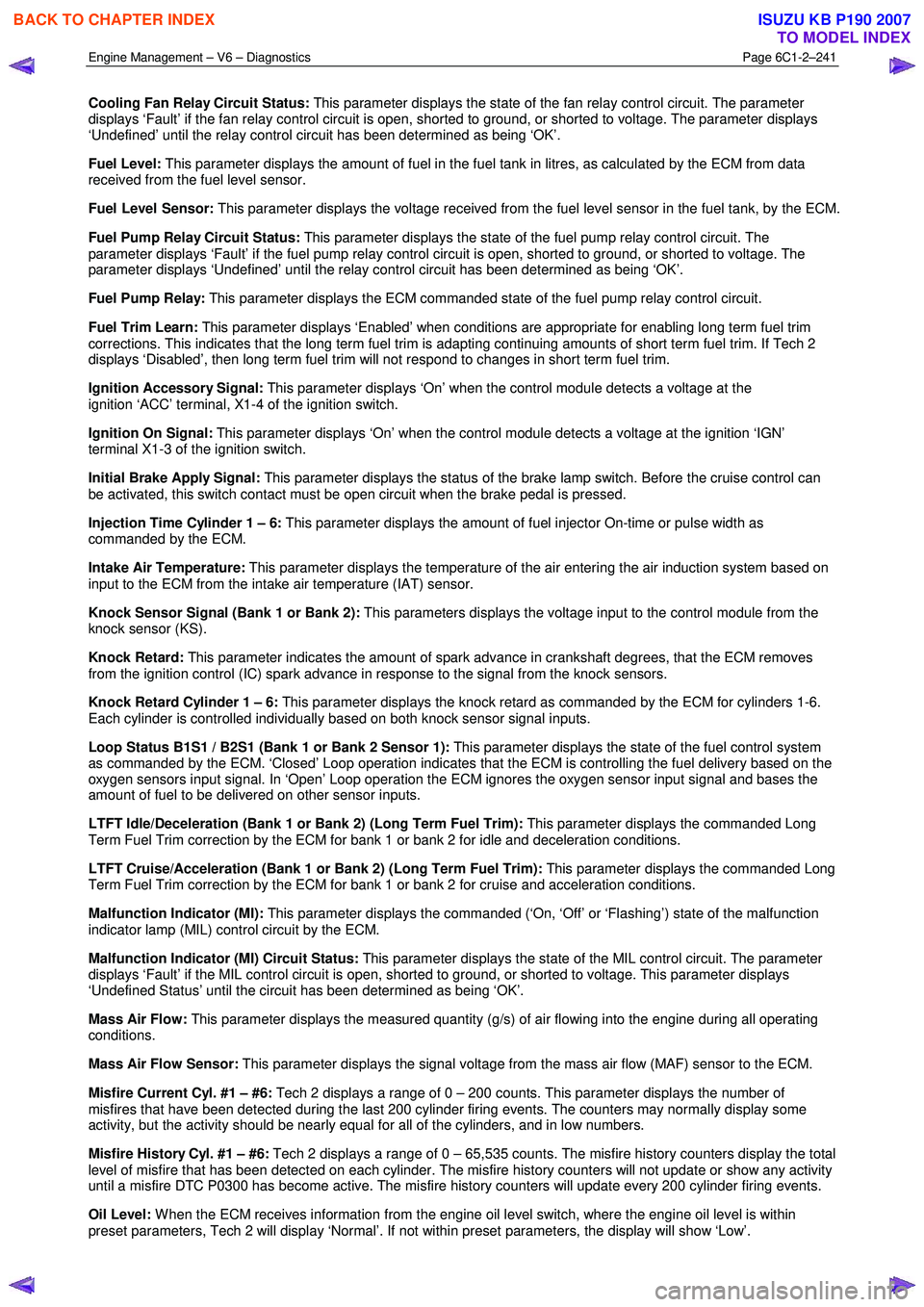
Cooling Fan Relay Circuit Status: This parameter displays the state of the fan relay control circuit. The parameter
displays ‘Fault’ if the fan relay control circuit is open, shorted to ground, or shorted to voltage. The parameter displays
‘Undefined’ until the relay control circuit has been determined as being ‘OK’.
Fuel Level: This parameter displays the amount of fuel in the fuel tank in litres, as calculated by the ECM from data
received from the fuel level sensor.
Fuel Level Sensor: This parameter displays the voltage received from the fuel level sensor in the fuel tank, by the ECM.
Fuel Pump Relay Circuit Status: This parameter displays the state of the fuel pump relay control circuit. The
parameter displays ‘Fault’ if the fuel pump relay control circuit is open, shorted to ground, or shorted to voltage. The
parameter displays ‘Undefined’ until the relay control circuit has been determined as being ‘OK’.
Fuel Pump Relay: This parameter displays the ECM commanded state of the fuel pump relay control circuit.
Fuel Trim Learn: This parameter displays ‘Enabled’ when conditions are appropriate for enabling long term fuel trim
corrections. This indicates that the long term fuel trim is adapting continuing amounts of short term fuel trim. If Tech 2
displays ‘Disabled’, then long term fuel trim will not respond to changes in short term fuel trim.
Ignition Accessory Signal: This parameter displays ‘On’ when the control module detects a voltage at the
ignition ‘ACC’ terminal, X1-4 of the ignition switch.
Ignition On Signal: This parameter displays ‘On’ when the control module detects a voltage at the ignition ‘IGN’
terminal X1-3 of the ignition switch.
Initial Brake Apply Signal: This parameter displays the status of the brake lamp switch. Before the cruise control can
be activated, this switch contact must be open circuit when the brake pedal is pressed.
Injection Time Cylinder 1 – 6: This parameter displays the amount of fuel injector On-time or pulse width as
commanded by the ECM.
Intake Air Temperature: This parameter displays the temperature of the air entering the air induction system based on
input to the ECM from the intake air temperature (IAT) sensor.
Knock Sensor Signal (Bank 1 or Bank 2): This parameters displays the voltage input to the control module from the
knock sensor (KS).
Knock Retard: This parameter indicates the amount of spark advance in crankshaft degrees, that the ECM removes
from the ignition control (IC) spark advance in response to the signal from the knock sensors.
Knock Retard Cylinder 1 – 6: This parameter displays the knock retard as commanded by the ECM for cylinders 1-6.
Each cylinder is controlled individually based on both knock sensor signal inputs.
Loop Status B1S1 / B2S1 (Bank 1 or Bank 2 Sensor 1): This parameter displays the state of the fuel control system
as commanded by the ECM. ‘Closed’ Loop operation indicates that the ECM is controlling the fuel delivery based on the
oxygen sensors input signal. In ‘Open’ Loop operation the ECM ignores the oxygen sensor input signal and bases the
amount of fuel to be delivered on other sensor inputs.
LTFT Idle/Deceleration (Bank 1 or Bank 2) (Long Term Fuel Trim): This parameter displays the commanded Long
Term Fuel Trim correction by the ECM for bank 1 or bank 2 for idle and deceleration conditions.
LTFT Cruise/Acceleration (Bank 1 or Bank 2) (Long Term Fuel Trim): This parameter displays the commanded Long
Term Fuel Trim correction by the ECM for bank 1 or bank 2 for cruise and acceleration conditions.
Malfunction Indicator (MI): This parameter displays the commanded (‘On, ‘Off’ or ‘Flashing’) state of the malfunction
indicator lamp (MIL) control circuit by the ECM.
Malfunction Indicator (MI) Circuit Status: This parameter displays the state of the MIL control circuit. The parameter
displays ‘Fault’ if the MIL control circuit is open, shorted to ground, or shorted to voltage. This parameter displays
‘Undefined Status’ until the circuit has been determined as being ‘OK’.
Mass Air Flow: This parameter displays the measured quantity (g/s) of air flowing into the engine during all operating
conditions.
Mass Air Flow Sensor: This parameter displays the signal voltage from the mass air flow (MAF) sensor to the ECM.
Misfire Current Cyl. #1 – #6: Tech 2 displays a range of 0 – 200 counts. This parameter displays the number of
misfires that have been detected during the last 200 cylinder firing events. The counters may normally display some
activity, but the activity should be nearly equal for all of the cylinders, and in low numbers.
Misfire History Cyl. #1 – #6: Tech 2 displays a range of 0 – 65,535 counts. The misfire history counters display the total
level of misfire that has been detected on each cylinder. The misfire history counters will not update or show any activity
until a misfire DTC P0300 has become active. The misfire history counters will update every 200 cylinder firing events.
Oil Level: W hen the ECM receives information from the engine oil level switch, where the engine oil level is within
preset parameters, Tech 2 will display ‘Normal’. If not within preset parameters, the display will show ‘Low’.
BACK TO CHAPTER INDEX
TO MODEL INDEX
ISUZU KB P190 2007
Page 3520 of 6020
Engine Management – V6 – Diagnostics Page 6C1-2–242
Oil Temperature Sensor: This parameter displays the engine oil temperature in degrees C.
Power Enrichment: This parameter displays the status of the operating mode of the ECM used to increase fuel delivery
during certain acceleration conditions.
Reduced Engine Power: This parameter displays when the ECM is commanding reduced engine power due to a
throttle actuator control (TAC) system condition.
Requested Torque: This parameter displays the calculated amount torque requested of the ECM by the Transmission
Control Module (TCM).
Short Term Fuel Trim (Bank 1 or Bank 2): This parameter displays the short-term correction to the fuel delivery by the
ECM in response to oxygen sensor 1 or 2. If the oxygen sensor indicates a lean air/fuel mixture, the control module will
add fuel, increasing the short term fuel trim above 0. If the oxygen sensor indicates a rich air/fuel mixture, the control
module will reduce fuel decreasing the short term fuel trim below 0.
Spark Advance: This parameter displays the amount of spark advance the ECM is commanding on the ignition control
circuits. The ECM determines the desired advance.
Starter Relay: This parameter displays the Em’s commanded state of the starter motor relay control circuit.
Starter Relay Circuit Status: This parameter displays the state of the starter relay control circuit. The parameter
displays ‘Fault’ if the starter relay control circuit is open, shorted to ground, or shorted to voltage. The parameter
displays Undefined Status’ until the circuit has been determined as being ‘OK’. This parameter may not change if Tech 2
is used to command the relay control circuit ON.
Start Up ECT (Engine Coolant Temperature): This parameter displays the temperature of the engine coolant on start
up based on input to the ECM from the ECT sensor.
Start Up IAT (Intake Air Temperature): This parameter displays the temperature of the intake air at start in the air
induction system based on input to the ECM from the IAT sensor.
Time Since Engine Off: This parameter displays the amount of time (hours:minutes:seconds) that has elapsed since
the engine was last cycled OFF.
Total Fuel Trim (Bank 1 or Bank 2): This parameter displays the overall fuel trim from the idle/decel cell and the
cruise/accel cell.
Total Misfire: This parameter displays the total number of cylinder firing events that the control module detected as
misfires for the last 200 crankshaft revolution sample period.
TP Sensor 1 (Throttle Position): This parameter displays the actual voltage on the TP sensor 1 signal circuit as
measured by the ECM.
TP Sensor 1 Learned Lower Position (Throttle Position): This parameter displays the learned minimum value of TP
sensor 1 as recorded by the ECM during the last learn procedure.
TP Sensor 2 (Throttle Position): This parameter displays the actual voltage on the TP sensor 2 signal circuit as
measured by the ECM.
TP Sensor 2 Learned Lower Position (Throttle Position): This parameter displays the learned minimum value of TP
sensor 2 as recorded by the ECM during the last learn procedure.
TP Sensor 1-2 Correlation (Throttle Position): This parameter displays ‘Fault’ when the ECM detects that TP sensor 1
voltage signal is not within the correct relationship to TP sensor 2. Tech 2 displays ‘Okay’ under normal operating
conditions.
Transmission Gear: This parameter displays the position of the transmission gear selector that is transmitted over the
serial data circuit from the TCM.
Transmission Gear Selector Signal: This parameter displays the position of the transmission gear selector that is
transmitted over the serial data circuit from the TCM.
Vehicle Speed: This parameter displays the speed of the vehicle as calculated by the TCM from information received
from the vehicle speed sensor (VSS).
Volumetric Efficiency: This parameter displays the volumetric efficiency of the engine as calculated by the control
module.
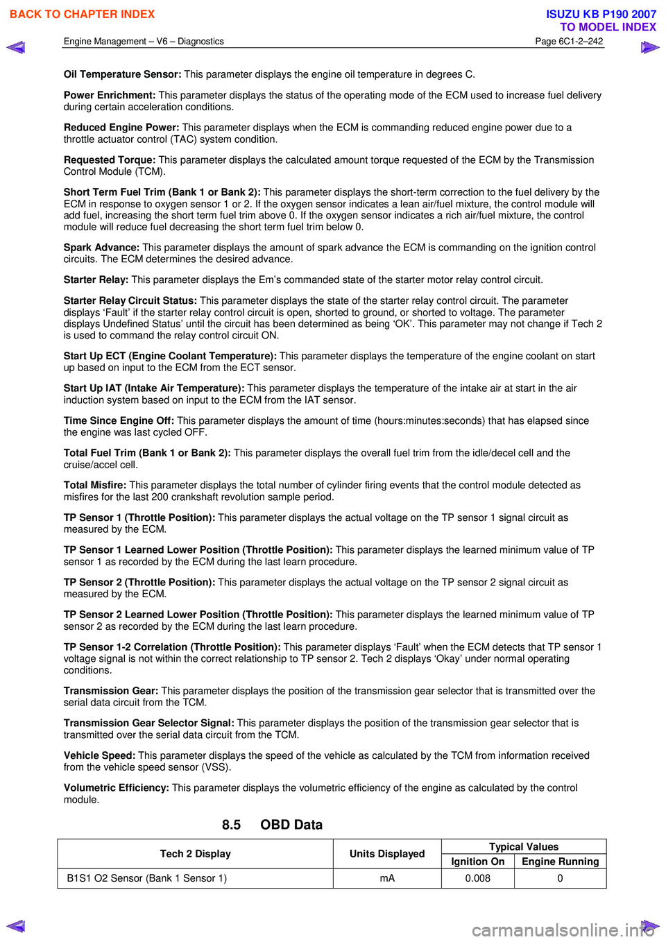
8.5 OBD Data
Typical Values Tech 2 Display Units Displayed
Ignition On Engine Running
B1S1 O2 Sensor (Bank 1 Sensor 1) mA 0.008 0
BACK TO CHAPTER INDEX
TO MODEL INDEX
ISUZU KB P190 2007
Page 3613 of 6020
Starting System – V6 Page 6D1-2–5
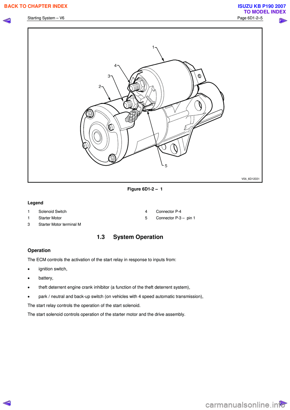
Figure 6D1-2 – 1
Legend
1 Solenoid Switch
1 Starter Motor
3 Starter Motor terminal M 4 Connector P-4
5 Connector P-3 – pin 1
1.3 System Operation
Operation
The ECM controls the activation of the start relay in response to inputs from:
• ignition switch,
• battery,
• theft deterrent engine crank inhibitor (a function of the theft deterrent system),
• park / neutral and back-up switch (on vehicles with 4 speed automatic transmission),
The start relay controls the operation of the start solenoid.
The start solenoid controls operation of the starter motor and the drive assembly.
BACK TO CHAPTER INDEX
TO MODEL INDEX
ISUZU KB P190 2007
Page 3646 of 6020

Battery Page 6D1-3–6
2 Safety Precautions
• Battery fluid contains sulphuric acid,
which can cause serious injury. Do not
allow liquid from the battery to contact
eyes or skin. If contact occurs, flush the
area immediately with running water and
contact a physician.
• Lead acid batteries produce explosive
gases. Keep sparks, flames and lighted
cigarettes away from the battery,
especially when the battery is being
charged. Failure to follow this warning
could result in a battery explosion.
• Metal objects that touch a battery terminal
can produce sparks that can cause
serious burns. When working near a
battery, take extra care with metal objects
including tools and items of jewellery,
especially rings and metal watchbands.
Do not allow liquid from the battery to contact
clothing or painted surfaces. If contact occurs,
flush the area immediately with running water.
W hen working with or near the battery, always:
• W ear safety glasses and work gloves.
• Remove items of jewellery such as rings and metal watchbands.
• Ensure the ignition is switched off when connecting or disconnecting battery cables, battery charging equipment or
battery jumper cables. Failing to do so can damage the vehicle electronic components.
• Disconnect the negative battery cable before disconnecting the positive cable from the battery. Inversely, connect
the positive battery cable to the battery before connecting the negative cable. This reduces the possibility of
shorting the battery to ground while working near the positive connections.
BACK TO CHAPTER INDEX
TO MODEL INDEX
ISUZU KB P190 2007
Page 3673 of 6020

Powertrain Interface Module – V6 Page 6E1–12
3 Component Description and
Operation
3.1 Powertrain Interface Module
The powertrain interface module (PIM) is located behind the
right-hand lower hinge pillar trim.
Figure 6E1 – 5
The PIM performs the following functions:
• The PIM acts as the communication gateway between the GM LAN communications protocol and keyword 2000
protocol.
• The PIM converts analogue signals from the cruise control switches into digital serial data.
• The PIM upon inputs received from the engine control module (ECM), transmission control module (TCM) and
immobiliser control unit (ICU) controls the operation of the following instruments and warning lamps:
• Speedometer
• Tachometer
• Check Transmission Lamp
• 3
rd Gear Start Lamp
• Power Mode Switch Lamp
• Automatic Transmission Oil Temp Lamp
• Cruise Set Lamp
• Oil Pressure Lamp
• Service Vehicle Soon (SVS) Lamp
• Charge W arning Lamp
• PRNDL Lamps
• The PIM is responsible for authenticating the immobiliser control unit (ICU) prior to the engine control module
(ECM) authenticating the PIM. If any of these authentication processes fail, the vehicle will not start. For further
information on the immobiliser system, refer to 11A Immobiliser System.
BACK TO CHAPTER INDEX
TO MODEL INDEX
ISUZU KB P190 2007
Page 3728 of 6020
Powertrain Interface Module – V6 Page 6E1–67
10.3 Tachometer Diagnostics
Circuit Description
The powertrain interface module (PIM) receives the tachomer signal from the engine control module (ECM), it is then
sent to the instrument cluster by the PIM via a hard wired connection to drive the tachometer which displays the engine
RPM. Some of these components do not set a DTC, in the event of a component failure. The following diagnostic
procedures are devised to assist in these cases.
Additional Information
• Refer to 7.2 Diagnostic System Check to monitor DTC’s.
• Refer to 8A Electrical Body and Chassis for the following information:
• ECM wiring diagram.
• Refer to 6 W iring Diagram and Connector Chart for the following information:
• PIM connector illustration and terminal assignment, and
• PIM wiring diagram.
• For intermittent faults, refer to Intermittent Fault Conditions.
• Check for an intermittent fault in the wiring harness or connectors, if a fault cannot be found the system is
serviceable.
Since fault conditions in a wiring connector may trigger DTCs, always test the connectors related to this diagnostic
procedure for shorted terminals or poor wiring connection before replacing any component. Refer to 8A Electrical - Body
and Chassis for information on electrical fault diagnosis.
Test Description
The following numbers refer to the step numbers in the diagnostic table:
1 This step tests for DTC’s in the overall system.
2 This step uses the instrument cluster self test to check the function of the tachometer.
3 This step uses Tech 2 to drive the tachometer.
6 This step tests for tachometer drive frequency.
10 This step tests the in-vehicle function of the tachometer.
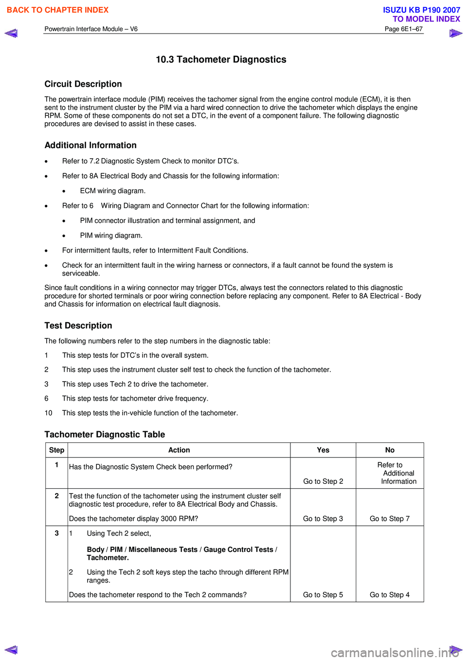
Tachometer Diagnostic Table
Step Action Yes No
1
Has the Diagnostic System Check been performed?
Go to Step 2 Refer to
Additional
Information
2 Test the function of the tachometer using the instrument cluster self
diagnostic test procedure, refer to 8A Electrical Body and Chassis.
Does the tachometer display 3000 RPM? Go to Step 3 Go to Step 7
3 1 Using Tech 2 select,
Body / PIM / Miscellaneous Tests / Gauge Control Tests /
Tachometer.
2 Using the Tech 2 soft keys step the tacho through different RPM ranges.
Does the tachometer respond to the Tech 2 commands? Go to Step 5 Go to Step 4
BACK TO CHAPTER INDEX
TO MODEL INDEX
ISUZU KB P190 2007
Page 3731 of 6020
Powertrain Interface Module – V6 Page 6E1–70
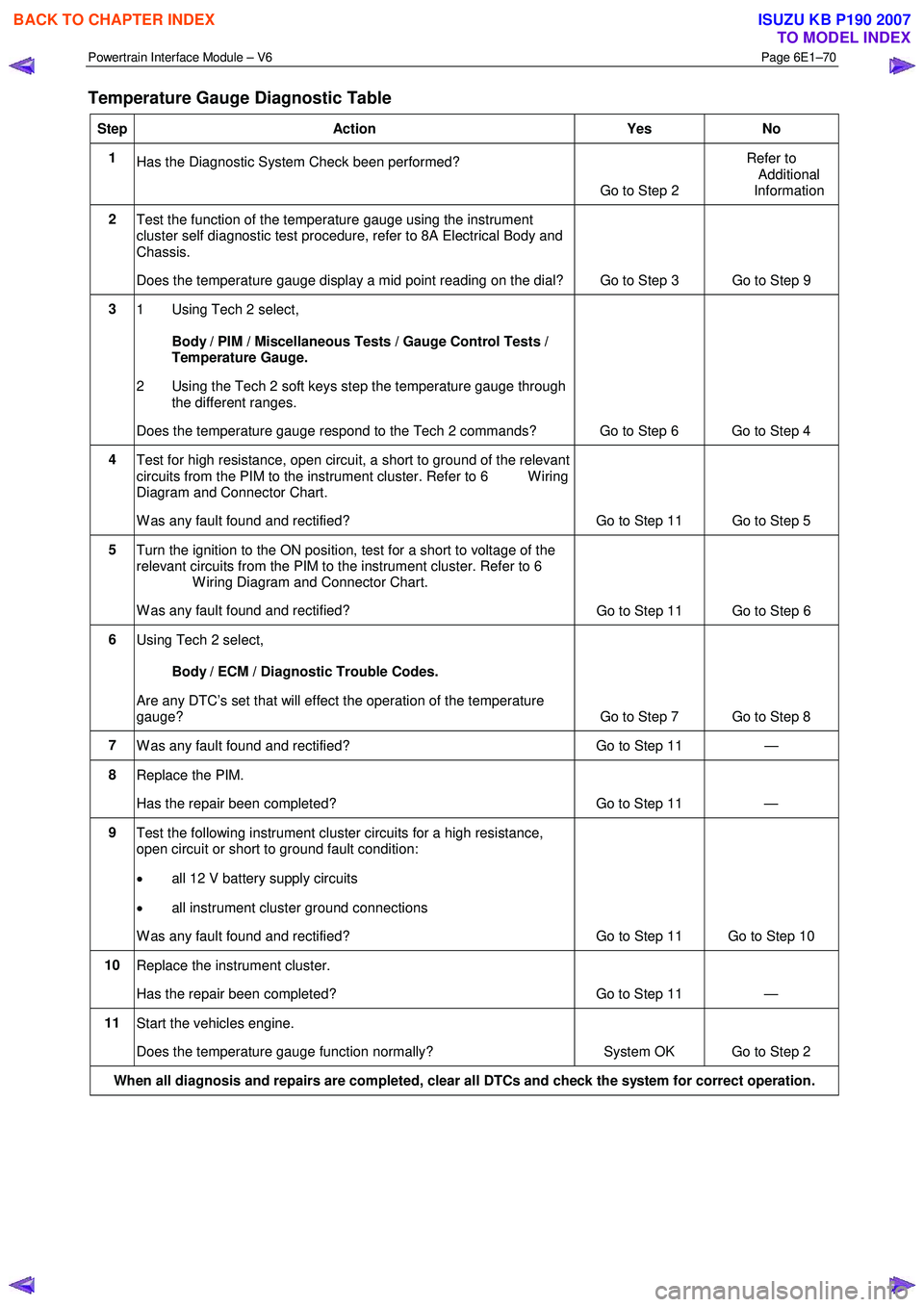
Temperature Gauge Diagnostic Table
Step Action Yes No
1
Has the Diagnostic System Check been performed?
Go to Step 2 Refer to
Additional
Information
2 Test the function of the temperature gauge using the instrument
cluster self diagnostic test procedure, refer to 8A Electrical Body and
Chassis.
Does the temperature gauge display a mid point reading on the dial? Go to Step 3 Go to Step 9
3
1 Using Tech 2 select,
Body / PIM / Miscellaneous Tests / Gauge Control Tests /
Temperature Gauge.
2 Using the Tech 2 soft keys step the temperature gauge through the different ranges.
Does the temperature gauge respond to the Tech 2 commands? Go to Step 6 Go to Step 4
4 Test for high resistance, open circuit, a short to ground of the relevant
circuits from the PIM to the instrument cluster. Refer to 6 W iring
Diagram and Connector Chart.
W as any fault found and rectified? Go to Step 11 Go to Step 5
5 Turn the ignition to the ON position, test for a short to voltage of the
relevant circuits from the PIM to the instrument cluster. Refer to 6
W iring Diagram and Connector Chart.
W as any fault found and rectified? Go to Step 11 Go to Step 6
6
Using Tech 2 select,
Body / ECM / Diagnostic Trouble Codes.
Are any DTC’s set that will effect the operation of the temperature
gauge? Go to Step 7 Go to Step 8
7 W as any fault found and rectified? Go to Step 11 —
8 Replace the PIM.
Has the repair been completed? Go to Step 11 —
9 Test the following instrument cluster circuits for a high resistance,
open circuit or short to ground fault condition:
• all 12 V battery supply circuits
• all instrument cluster ground connections
W as any fault found and rectified? Go to Step 11 Go to Step 10
10 Replace the instrument cluster.
Has the repair been completed? Go to Step 11 —
11 Start the vehicles engine.
Does the temperature gauge function normally? System OK Go to Step 2
When all diagnosis and repairs are completed, clear all DTCs and check the system for correct operation.
BACK TO CHAPTER INDEX
TO MODEL INDEX
ISUZU KB P190 2007
Page 3801 of 6020

Automatic Transmission – 4L60E – Electrical Diagnosis Page 7C2–15
• 2-3 Shift Data – Once this mode is selected, displays specific parameter information about the 2-3 shift solenoid
valve (shift solenoid B) and its circuits.
• 3-4 Shift Data – Once selected, displays information on 3-4 shift timing.
• 3-2 Downshift Data – Once selected, displays information on 3-2 downshift timing.
• Pressure Control Solenoid Data – Once selected, displays specific parameter information about the PC solenoid
and its circuits.
• Transmission Adapts – Once selected, it has further sub menus:
• 1-2 Adapt Data – In this mode Tech 2 continuously monitors and displays 1-2 TAP cell data parameters.
• 2-3 Adapt Data –In this mode Tech 2 continuously monitors and displays 2-3 TAP cell data parameters.
• 3-4 Adapt Data –In this mode Tech 2 continuously monitors and displays 3-4 TAP cell data parameters.
• Steady State Adapt Data – In this mode Tech 2 continuously monitors and displays Steady State TAP data
parameters.
• System Identification: In this mode, Tech 2 will display the transmission identification screen. The following items
will be displayed; Identifier, Partnumber, Hardware Partnumber, Alpha Code, Software Version Number, Software
Partnumber, VIN Digit 1-10, VIN Digit 11-17.
NOTE
Further information about the Data Display mode
and the data parameter is contained in
3.2 Data Display.
Snapshot
In this test mode, Tech 2 captures TCM data before and after a forced manual trigger.
Additional Functions
If Additional Functions is selected, a selections list is displayed which contains:
• System Identification – In this mode, Tech 2 will display the transmission identification screen. The following items
will be displayed; Identifier, Partnumber, Hardware Partnumber, Alpha Code, Software Version Number, Software
Partnumber.
Miscellaneous Tests
If Miscellaneous Functions is selected, a selections list is displayed which contains:
• TCC Solenoid –Tech 2 can command the TCC solenoid on and off. Tech 2 will display whether the TCC solenoid
is active or inactive.
• TCC PWN Solenoid – Tech 2 can command the TCC PWM solenoid on and off. Tech 2 will display whether the
TCC PWM solenoid is active or inactive and torque percentage.
• TCC Apply – Tech 2 can command the TCC on when the vehicle is above 50 km/h.
• Shift Solenoid A – Tech 2 can command the shift solenoid A (1-2 shift solenoid) on and off.
• Shift Solenoid B – Tech 2 can command the shift solenoid B (2-3 shift solenoid) on and off.
• 3/2 Downshift Solenoid – Tech 2 can command the 3/2 downshift solenoid (3-2 shift solenoid) on and off.
• Gear Control – Tech 2 can incrementally command shift solenoid states to correspond to relative gear states. The
TCM will only allow single shift increments or decrements and does not allow a shift if it causes the engine RPM to
exceed a calibrated limit.
• Pressure Control Solenoid – This function allows the user to control state of the pressure control solenoid in
increments of 100 mA.
NOTE
For operating parameters of the
Miscellaneous Test, refer to 3.4 Miscellaneous Tests.
BACK TO CHAPTER INDEX
TO MODEL INDEX
ISUZU KB P190 2007
Page 3809 of 6020
Automatic Transmission – 4L60E – Electrical Diagnosis Page 7C2–23
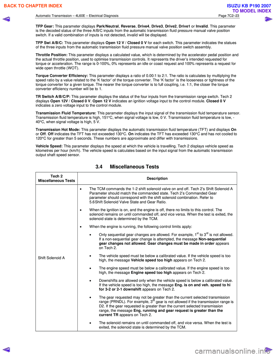
TFP Gear: This parameter displays Park/Neutral, Reverse , Drive4 , Drive3 , Drive2 , Drive1 or Invalid . This parameter
is the decoded status of the three A/B/C inputs from the automatic transmission fluid pressure manual valve position
switch. If a valid combination of inputs is not detected, invalid will be displayed.
TFP Swi A/B/C: This parameter displays Open 12 V / Closed 0 V for each switch. This parameter indicates the statues
of the three inputs from the automatic transmission fluid pressure manual valve position switch assembly.
Throttle Position: This parameter displays a calculated value, which is determined by the accelerator pedal position and
the actual throttle position, used to optimise transmission controls. It represents the driver’s intended requested for
torque or acceleration. The range is 0-100%, 0% represents an idle or coast request and 100% represents a request for
wide open throttle (WOT).
Torque Converter Efficiency: This parameter displays a ratio of 0.00:1 to 2:1. The ratio is calculates by multiplying the
speed ratio by a value related to the ‘K factor’ of the torque converter. The ‘K factor’ is the looseness or tightness of the
torque converter for a given torque. The nearer the torque converter is to full coupling, i.e. 1:1, the closer the torque
converter efficiency number will be to 1.
TR Switch A/B/C/P: This parameter displays the status of the four inputs from the transmission range switch. Tech 2
displays Open 12V / Closed 0 V . Open 12 V indicates an ignition voltage input to the control module. Closed 0 V
indicates a zero voltage input to the control module.
Transmission Fluid Temperature: This parameter displays the input signal of the transmission fluid temperature sensor.
Transmission fluid temperature is high, 151°C, when signal voltage is low, 0 V. Transmission fluid temperature is low, -
40°C, when signal voltage is high, 5 V.
Transmission Hot Mode: This parameter displays the automatic transmission fluid temperature (TFT) and displays On
or Off . Off indicates the TFT has not exceeded 130°C. On indicates the TFT has exceeded 130°C and has not cooled to
120°C for greater than 5 seconds. These numbers are approximate and differ with transmissions.
Vehicle Speed: This parameter displays the speed at which the vehicle is travelling. Tech 2 displays vehicle speed as
kilometres per hour (km/h). The vehicle speed is calculates based on the input signal from the automatic transmission
output shaft speed sensor.
3.4 Miscellaneous Tests
Tech 2
Miscellaneous Tests Description
Shift Solenoid A •
The TCM commands the 1-2 shift solenoid valve on and off. Tech 2’s Shift Solenoid A
Parameter should match the commanded state. Tech 2’s Commanded Gear
parameter should correspond with the shift solenoid combination. Refer to
5.6 Shift Solenoid Valve State and Gear Ratio.
• When the ignition is on, and the engine is off, there no limits to this control. The
solenoid remains on until commanded off, and vice versa. W hen the test is exited, the
solenoid state is determined by the TCM.
• W hen the engine is running, the following control limits apply:
• Only sequential gear changes are allowed. For example, 1
st to 3rd is not allowed.
If a non-sequential gear change is attempted, the message Non-sequential
gear changes not allowed . Gear changes must be made in order appears
on Tech 2.
• The vehicle speed must be below a calibrated value. If the vehicle speed is too
high, the message Vehicle speed too high appears on Tech 2.
• The engine speed must be below a calibrated value. If the engine speed is too
high, the message Engine speed too high appears on Tech 2.
• Downshifts are allowed only when the vehicle speed is below a calibrated value.
If the vehicle speed is too high, the message Eng. is on and veh. speed to hi
for 3-2 or 2-1 downshift appears on Tech 2.
• The gear requested may not be greater than the current selected transmission
range (PRNDL). For example, 3
rd gear is not allowed if the transmission range is
D2. If the gear requested is greater than the current selected transmission
range, the message Eng. running and gear request is greater than the
current TR appears on Tech 2.
• The solenoid remains on until commanded off, and vice versa. W hen the test is
exited, the solenoid state is determined by the TCM.
BACK TO CHAPTER INDEX
TO MODEL INDEX
ISUZU KB P190 2007
Page 3810 of 6020
Automatic Transmission – 4L60E – Electrical Diagnosis Page 7C2–24
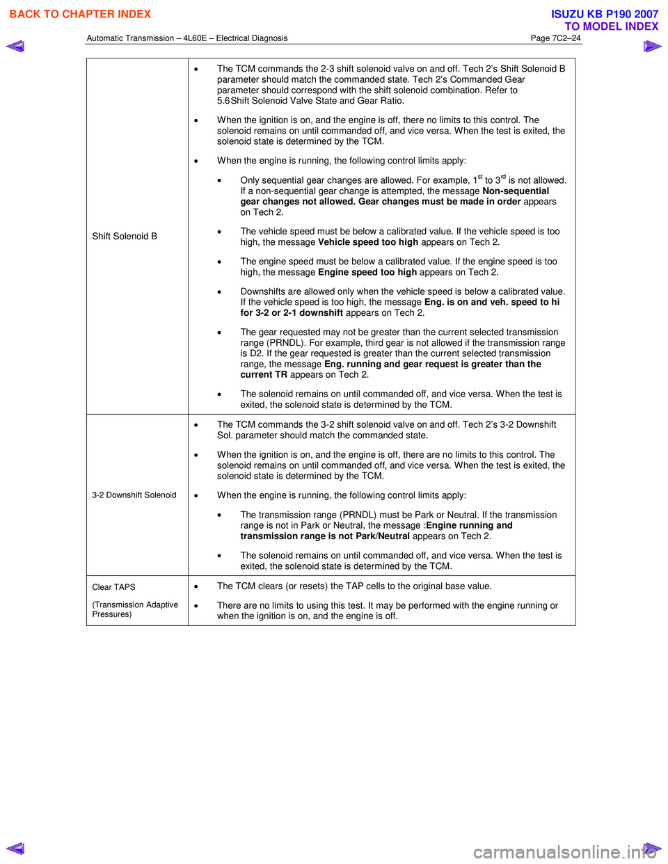
Shift Solenoid B •
The TCM commands the 2-3 shift solenoid valve on and off. Tech 2’s Shift Solenoid B
parameter should match the commanded state. Tech 2’s Commanded Gear
parameter should correspond with the shift solenoid combination. Refer to
5.6 Shift Solenoid Valve State and Gear Ratio.
• When the ignition is on, and the engine is off, there no limits to this control. The
solenoid remains on until commanded off, and vice versa. W hen the test is exited, the
solenoid state is determined by the TCM.
• W hen the engine is running, the following control limits apply:
• Only sequential gear changes are allowed. For example, 1
st to 3rd is not allowed.
If a non-sequential gear change is attempted, the message Non-sequential
gear changes not allowed. Gear changes must be made in order appears
on Tech 2.
• The vehicle speed must be below a calibrated value. If the vehicle speed is too
high, the message Vehicle speed too high appears on Tech 2.
• The engine speed must be below a calibrated value. If the engine speed is too
high, the message Engine speed too high appears on Tech 2.
• Downshifts are allowed only when the vehicle speed is below a calibrated value.
If the vehicle speed is too high, the message Eng. is on and veh. speed to hi
for 3-2 or 2-1 downshift appears on Tech 2.
• The gear requested may not be greater than the current selected transmission
range (PRNDL). For example, third gear is not allowed if the transmission range
is D2. If the gear requested is greater than the current selected transmission
range, the message Eng. running and gear request is greater than the
current TR appears on Tech 2.
• The solenoid remains on until commanded off, and vice versa. W hen the test is
exited, the solenoid state is determined by the TCM.
3-2 Downshift Solenoid
• The TCM commands the 3-2 shift solenoid valve on and off. Tech 2’s 3-2 Downshift
Sol. parameter should match the commanded state.
• When the ignition is on, and the engine is off, there are no limits to this control. The
solenoid remains on until commanded off, and vice versa. W hen the test is exited, the
solenoid state is determined by the TCM.
• W hen the engine is running, the following control limits apply:
• The transmission range (PRNDL) must be Park or Neutral. If the transmission
range is not in Park or Neutral, the message : Engine running and
transmission range is not Park/Neutral appears on Tech 2.
• The solenoid remains on until commanded off, and vice versa. W hen the test is
exited, the solenoid state is determined by the TCM.
Clear TAPS
(Transmission Adaptive
Pressures) • The TCM clears (or resets) the TAP cells to the original base value.
• There are no limits to using this test. It may be performed with the engine running or
when the ignition is on, and the engine is off.
BACK TO CHAPTER INDEX
TO MODEL INDEX
ISUZU KB P190 2007