Circuit ISUZU KB P190 2007 Workshop Repair Manual
[x] Cancel search | Manufacturer: ISUZU, Model Year: 2007, Model line: KB P190, Model: ISUZU KB P190 2007Pages: 6020, PDF Size: 70.23 MB
Page 3615 of 6020

Starting System – V6 Page 6D1-2–7
2 Diagnostics
2.1 Diagnostic General Information
NOTE
There is a minimum battery voltage threshold
value. If the battery voltage is below the set value,
the ECU will inhibit cranking. Refer to 6C1-1
Engine Management – V6 – General Information
for further information.
Basic Diagnostic Tools Required
Use of incorrect electrical circuit diagnostic
tools when performing the cruise control
diagnostic procedures could result in
incorrect diagnostic results or damage to
components.
The following electrical circuit testing tools are required to perform the diagnostic procedures detailed in this Section:
• digital multimeter with 10 meg ohms impedance, and
• connector test adapter kit Tool No. KM609.
For further information on the use of these tools, refer to 8A Electrical Body and Chassis.
2.2 Tech 2 Data List
The Tech 2 displays the status of certain starting system parameters.
To view the data list:
1 Connect Tech 2 to the DLC.
2 On Tech 2 select: Engine / V6 Engine / Data Display / Data List / Electrical / Theft Data .
Tech 2 Parameter Units Displayed Typical Display Values
Crank Request Inactive / Active Inactive
Starter Relay Off / On Off
2.3 Diagnostic Systems Check
Step Action Yes No
1
Is the fault specifically isolated to this system / module?
Go to Step 2 Go to 0D Vehicle
Diagnostics
2 1 Connect Tech 2 to the DLC.
2 Ignition ON, engine OFF.
3 On Tech 2 select:
Engine / V6 Engine / Diagnostic Trouble codes / Read
DTC’s.
Are there any set DTC’s? Go to the
appropriate DTC
table in 6C1-2 Engine
Management – V6 – Diagnostics. Refer to 2.5
Starting
System Inoperative / Malfunctioning
BACK TO CHAPTER INDEX
TO MODEL INDEX
ISUZU KB P190 2007
Page 3618 of 6020

Starting System – V6 Page 6D1-2–10
2.5 Starting System Inoperative /
Malfunctioning
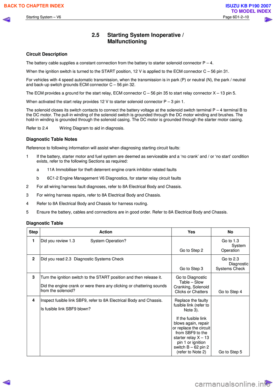
Circuit Description
The battery cable supplies a constant connection from the battery to starter solenoid connector P – 4.
W hen the ignition switch is turned to the START position, 12 V is applied to the ECM connector C – 56 pin 31.
For vehicles with 4 speed automatic transmission, when the transmission is in park (P) or neutral (N), the park / neutral
and back-up switch grounds ECM connector C – 56 pin 32.
The ECM provides a ground for the start relay, ECM connector C – 56 pin 35 to start relay connector X – 13 pin 5.
W hen activated the start relay provides 12 V to starter solenoid connector P – 3 pin 1.
The solenoid closes its switch contacts to connect the battery voltage at the solenoid switch terminal P – 4 terminal B to
the DC motor. The pull-in winding of the solenoid switch is grounded through the DC motor winding and brushes. The
hold-in winding is grounded through the solenoid casing. The DC motor is grounded through the starter motor casing.
Refer to 2.4 W iring Diagram to aid in diagnosis.
Diagnostic Table Notes
Reference to following information will assist when diagnosing starting circuit faults:
1 If the battery, starter motor and fuel system are deemed as serviceable and a ‘no crank’ and / or ‘no start’ condition exists, refer to the following Sections as required:
a 11A Immobiliser for theft deterrent engine crank inhibitor related faults
b 6C1-2 Engine Management V6 Diagnostics, for starter relay circuit faults
2 For all wiring harness fault diagnoses, refer to 8A Electrical Body and Chassis.
3 For wiring harness repairs, refer to 8A Electrical Body and Chassis.
4 Refer to 8A Electrical Body and Chassis for harness routing.
5 Ensure the battery, cables and connections are in good order. Refer to 8A Electrical Body and Chassis.
Diagnostic Table
Step Action Yes No
1
Did you review 1.3 System Operation?
Go to Step 2 Go to 1.3
System
Operation
2 Did you read 2.3 Diagnostic Systems Check
Go to Step 3 Go to 2.3
Diagnostic Systems Check
3 Turn the ignition switch to the START position and then release it.
Did the engine crank or were there any clicking or chattering sounds
from the solenoid? Go to Diagnostic
Table – Slow
Cranking, Solenoid Clicks or Chatters Go to Step 4
4 Inspect fusible link SBF9, refer to 8A Electrical Body and Chassis.
Is fusible link SBF9 blown? Replace the faulty
fusible link (refer to
Note 3).
If the fusible link
blows again, repair
or replace the circuit from SBF9 to the
starter relay X – 13 pin 1 or ignition
switch B – 62 pin 2 (refer to Note 2) Go to Step 5
BACK TO CHAPTER INDEX
TO MODEL INDEX
ISUZU KB P190 2007
Page 3619 of 6020

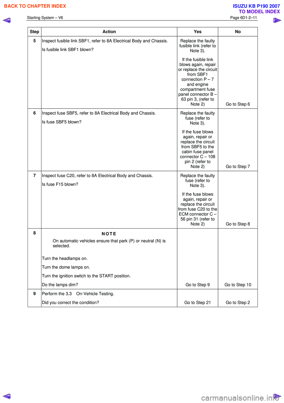
Starting System – V6 Page 6D1-2–11
Step Action Yes No
5
Inspect fusible link SBF1, refer to 8A Electrical Body and Chassis.
Is fusible link SBF1 blown? Replace the faulty
fusible link (refer to Note 3).
If the fusible link
blows again, repair
or replace the circuit from SBF1
connection P – 7
and engine
compartment fuse
panel connector B – 63 pin 3, (refer to
Note 2) Go to Step 6
6 Inspect fuse SBF5, refer to 8A Electrical Body and Chassis.
Is fuse SBF5 blown? Replace the faulty
fuse (refer to Note 3).
If the fuse blows again, repair or
replace the circuit from SBF5 to the cabin fuse panel
connector C – 108
pin 2 (refer to Note 2) Go to Step 7
7
Inspect fuse C20, refer to 8A Electrical Body and Chassis.
Is fuse F15 blown? Replace the faulty
fuse (refer to Note 3).
If the fuse blows again, repair or
replace the circuit
from fuse C20 to the ECM connector C –
56 pin 31 (refer to Note 2) Go to Step 8
8 NOTE
On automatic vehicles ensure that park (P) or neutral (N) is
selected.
Turn the headlamps on.
Turn the dome lamps on.
Turn the ignition switch to the START position.
Do the lamps dim? Go to Step 9 Go to Step 10
9
Perform the 3.3 On-Vehicle Testing.
Did you correct the condition?
Go to Step 21 Go to Step 2
BACK TO CHAPTER INDEX
TO MODEL INDEX
ISUZU KB P190 2007
Page 3620 of 6020

Starting System – V6 Page 6D1-2–12
Step Action Yes No
10
1 Connect Tech 2 to the DLC.
2 Ignition on, engine off.
3 On Tech 2 select: Engine / V6 Engine / Data Display / Data List /
Electrical/Theft Data.
4 On Tech 2 scroll to Crank Request.
5 W hile monitoring Tech 2, turn the ignition switch to START.
Does Tech 2 display the following:
Inactive with the ignition switch in the ON position, Active with the
ignition switch in the START position? Go to Step 15 Go to Step 11
11 1 Disconnect the ECM connector C – 56.
2 Using a multimeter set to measure voltage, back probe between the harness connector C56 – X2 pin 31 and ground.
3 W ith the aid of an assistant, monitor the voltage on the multimeter and turn the ignition switch to START.
• W ith the ignition switch in the START position, the
multimeter should display battery voltage
• W ith the ignition switch in the ON position, the multimeter
should display 0 V
Does the multimeter display as described? Refer to 6C1 - 3
Engine
Management – V6 – Service Operations
for further diagnosis.
Go to Step 21 Go to Step 12
12 Test the ignition switch, refer to 3B Steering.
Is the ignition switch serviceable?
Go to Step 13 Replace the faulty
ignition switch. Refer to 3B
Steering
Go to Step 21
13 Check for short to ground or open circuit from the ignition switch start
terminal to the ECM connector C – 56 pin 31.
W as the circuit serviceable? Go to Step 14 Repair as required
(refer to Note 2).
Go to Step 21
14 Check for short to ground or open circuit from the ignition switch
terminal B1 to the fuse SBF5.
W as the circuit serviceable? Go to Step 2 Repair as required
(refer to Note 2).
Go to Step 21
15 NOTE
This procedure is only required on vehicles fitted with
manual transmissions. If the vehicle is fitted with an
automatic transmission, go to Step 16
1 Scroll to Starter Relay
2 W hile monitoring Tech 2, turn the ignition switch to START.
Does Tech 2 display the following:
Off with the ignition switch in the ON position,
On with the ignition switch in the START position?
Go to Step 21 Go to Step 16
BACK TO CHAPTER INDEX
TO MODEL INDEX
ISUZU KB P190 2007
Page 3621 of 6020

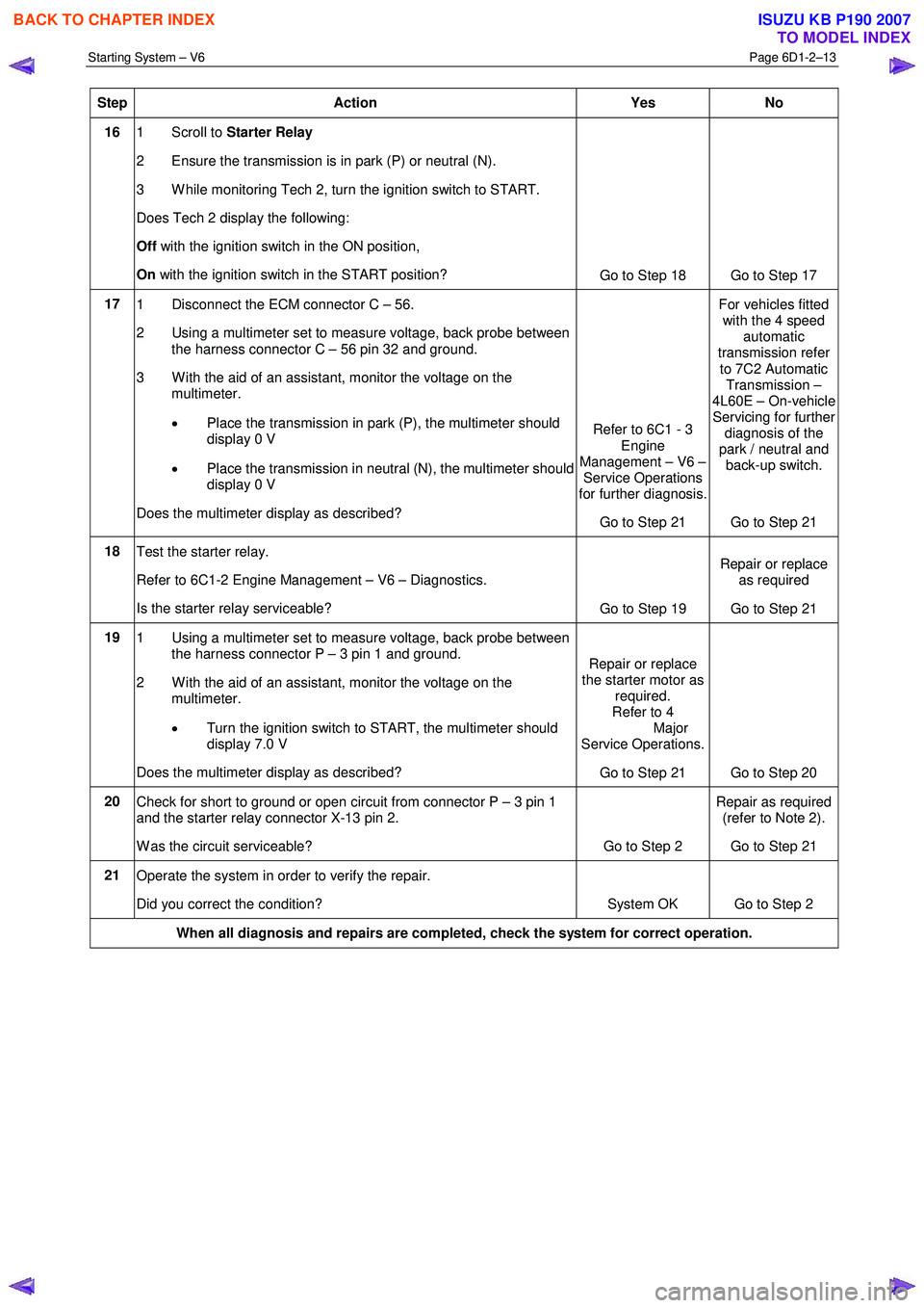
Starting System – V6 Page 6D1-2–13
Step Action Yes No
16 1 Scroll to Starter Relay
2 Ensure the transmission is in park (P) or neutral (N).
3 W hile monitoring Tech 2, turn the ignition switch to START.
Does Tech 2 display the following:
Off with the ignition switch in the ON position,
On with the ignition switch in the START position?
Go to Step 18 Go to Step 17
17 1 Disconnect the ECM connector C – 56.
2 Using a multimeter set to measure voltage, back probe between the harness connector C – 56 pin 32 and ground.
3 W ith the aid of an assistant, monitor the voltage on the multimeter.
• Place the transmission in park (P), the multimeter should
display 0 V
• Place the transmission in neutral (N), the multimeter should
display 0 V
Does the multimeter display as described? Refer to 6C1 - 3
Engine
Management – V6 – Service Operations
for further diagnosis.
Go to Step 21 For vehicles fitted
with the 4 speed automatic
transmission refer
to 7C2 Automatic Transmission –
4L60E – On-vehicle Servicing for further
diagnosis of the
park / neutral and back-up switch.
Go to Step 21
18 Test the starter relay.
Refer to 6C1-2 Engine Management – V6 – Diagnostics.
Is the starter relay serviceable? Go to Step 19 Repair or replace
as required
Go to Step 21
19 1 Using a multimeter set to measure voltage, back probe between
the harness connector P – 3 pin 1 and ground.
2 W ith the aid of an assistant, monitor the voltage on the multimeter.
• Turn the ignition switch to START, the multimeter should
display 7.0 V
Does the multimeter display as described? Repair or replace
the starter motor as required.
Refer to 4
Major
Service Operations.
Go to Step 21 Go to Step 20
20 Check for short to ground or open circuit from connector P – 3 pin 1
and the starter relay connector X-13 pin 2.
W as the circuit serviceable? Go to Step 2 Repair as required
(refer to Note 2).
Go to Step 21
21 Operate the system in order to verify the repair.
Did you correct the condition? System OK Go to Step 2
When all diagnosis and repairs are completed, check the system for correct operation.
BACK TO CHAPTER INDEX
TO MODEL INDEX
ISUZU KB P190 2007
Page 3624 of 6020

Starting System – V6 Page 6D1-2–16
Engine Compartment Relay And Fuse Panel
Figure 6D1-2 – 4
1 Remove fuses SBF5 and SBF9 from the engine compartment fuse panel to disable the ignition and prevent the engine from starting, refer to 8A Electrical Body and Chassis.
2 Chock the wheels.
3 For vehicles fitted with automatic transmission ensure the transmission is in P (park) or N (neutral) and the hand brake is applied.
4 Ensure the engine is at room temperature or normal operating temperature and in good working order.
Bad Connection Test
A bad connection appears as a voltage reading when the multimeter leads are connected to two different positive (or
negative) connections.
1 Using a multimeter set to measure voltage, connect the multimeter’s positive lead to the positive battery post.
2 Connect the multimeter’s negative lead to the starter motor M terminal.
3 Record the voltage that displayed during cranking.
4 Repeat this with the multimeter’s negative lead connected to the solenoid switch connector P – 4 pin B (circuit 1).
5 Also repeat this connecting the multimeter’s negative lead to the battery cable strands.
6 Restore all connections that show a significant resistance (voltage reading).
BACK TO CHAPTER INDEX
TO MODEL INDEX
ISUZU KB P190 2007
Page 3625 of 6020

Starting System – V6 Page 6D1-2–17
Starter Motor Ground Test
1 Using a multimeter set to measure voltage, connect
the multimeter’s positive lead (1) to the negative
battery post.
Connect the lead to the actual battery post
and not to the cable or connector.
2 Connect the multimeter’s negative lead (2) to the starter motor housing.
3 Record the voltage that displayed during cranking.
4 Repeat this connecting the multimeter’s negative lead to the battery cable strands.
5 Restore all ground connections that show a significant resistance.
Figure 6D1-2 – 5
Switching Circuit Test
1 Using a multimeter set to measure voltage, connect
the multimeter’s negative lead (1) to the solenoid
switch connector P – 3 pin 1.
2 Connect the multimeter‘s positive lead (2) to the positive battery post.
3 Crank the engine.
4 Record the voltage that displayed during cranking.
Maximum switching
circuit voltage difference.........................................2.5 V
5 If the voltage is above the specification, test the solenoid switching circuit to locate the cause of the
high resistance and restore the connection.
Figure 6D1-2 – 6
BACK TO CHAPTER INDEX
TO MODEL INDEX
ISUZU KB P190 2007
Page 3637 of 6020

Starting System – V6 Page 6D1-2–29
27 Replace the solenoid switch if the test lamp
illuminates poorly.
28 Set the power supply to 12 V (1).
29 Connect the power supply positive lead to the solenoid switch terminal P – 3 (2).
30 Connect the power supply negative lead to the solenoid switch housing (3).
31 Press the plunger in fully.
32 Release the plunger. The hold-in winding should hold the plunger in.
33 Replace the solenoid switch if the winding does not hold the plunger in.
34 Decrease the voltage until the plunger releases.
35 Record the multimeter reading.
36 Replace the solenoid switch if the voltage reading is significantly higher than the
specification.
Hold-in voltage @ 20 °C..........................1.7 – 3.0 V
37 Connect a test lamp between the solenoid
switch terminal P – 4 and the 12 volt power
supply.
38 Press the plunger in until the test lamp illuminates.
39 Attempt to press the plunger into the solenoid switch housing a further 1 mm.
40 Replace the solenoid switch if the plunger cannot move at least a further 1 mm.
Figure 6D1-2 – 26
41 Connect the positive lead of a 24 volt power supply (1) to the positive lead of a multimeter set
to measure voltage.
42 Connect the negative lead of a 24 volt power supply to the solenoid switch housing (2).
43 Connect the multimeter negative lead to the solenoid switch terminal P – 4 (3).
44 Press the plunger (4) in fully.
45 Release the plunger. The plunger should return to its rest position.
46 Replace the solenoid switch if the plunger does not return.
NOTE
This indicates the windings have an
internal winding short circuit. When the
solenoid switch is connected in this way,
the winding fields are in opposition to each
other.
Figure 6D1-2 – 27
BACK TO CHAPTER INDEX
TO MODEL INDEX
ISUZU KB P190 2007
Page 3640 of 6020

Starting System – V6 Page 6D1-2–32
7 Special Tools
Tool Number Illustration Description Tool Classification
KM609
Connector Test Adaptor Kit
Used when carrying out electrical
diagnostic circuit checks.
Previously released
Desirable
3588
(J39200)
Digital Multimeter
Must have at least 10 M Ω input
impedance and be capable of reading
frequencies.
Previously released.
Available
EN – 46114 Engine Lifting Brackets
Available
BACK TO CHAPTER INDEX
TO MODEL INDEX
ISUZU KB P190 2007
Page 3652 of 6020

Battery Page 6D1-3–12
9 Lock the doors and activate the theft deterrent system to arm the vehicle.
10 If the multimeter contains fuses, check they are serviceable.
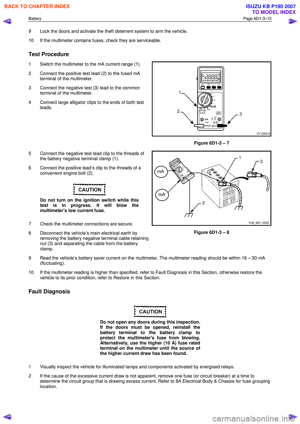
Test Procedure
1 Switch the multimeter to the mA current range (1).
2 Connect the positive test lead (2) to the fused mA terminal of the multimeter.
3 Connect the negative test (3) lead to the common terminal of the multimeter.
4 Connect large alligator clips to the ends of both test leads.
Figure 6D1-3 – 7
5 Connect the negative test lead clip to the threads of the battery negative terminal clamp (1).
6 Connect the positive lead’s clip to the threads of a convenient engine bolt (2).
Do not turn on the ignition switch while this
test is in progress. It will blow the
multimeter’s low current fuse.
7 Check the multimeter connections are secure.
8 Disconnect the vehicle’s main electrical earth by removing the battery negative terminal cable retaining
nut (3) and separating the cable from the battery
clamp.
Figure 6D1-3 – 8
9 Read the vehicle’s battery saver current on the multimeter. The multimeter reading should be within 16 – 30 mA (fluctuating).
10 If the multimeter reading is higher than specified, refer to Fault Diagnosis in this Section, otherwise restore the vehicle to its prior condition, refer to Restore in this Section.
Fault Diagnosis
Do not open any doors during this inspection.
If the doors must be opened, reinstall the
battery terminal to the battery clamp to
protect the multimeter's fuse from blowing.
Alternatively, use the higher (10 A) fuse rated
terminal on the multimeter until the source of
the higher current draw has been found.
1 Visually inspect the vehicle for illuminated lamps and components activated by energised relays.
2 If the cause of the excessive current draw is not apparent, remove one fuse (or circuit breaker) at a time to determine the circuit group that is drawing excess current. Refer to 8A Electrical Body & Chassis for fuse grouping
location.
BACK TO CHAPTER INDEX
TO MODEL INDEX
ISUZU KB P190 2007